EP0736343A2 - Blechspanneinrichtung, insbesondere für die Reparatur von Fahrzeugkarosserien oder dergleichen - Google Patents
Blechspanneinrichtung, insbesondere für die Reparatur von Fahrzeugkarosserien oder dergleichen Download PDFInfo
- Publication number
- EP0736343A2 EP0736343A2 EP96105327A EP96105327A EP0736343A2 EP 0736343 A2 EP0736343 A2 EP 0736343A2 EP 96105327 A EP96105327 A EP 96105327A EP 96105327 A EP96105327 A EP 96105327A EP 0736343 A2 EP0736343 A2 EP 0736343A2
- Authority
- EP
- European Patent Office
- Prior art keywords
- wedge
- clamp
- clamps
- fact
- double
- Prior art date
- Legal status (The legal status is an assumption and is not a legal conclusion. Google has not performed a legal analysis and makes no representation as to the accuracy of the status listed.)
- Withdrawn
Links
Images

Classifications
-
- B—PERFORMING OPERATIONS; TRANSPORTING
- B21—MECHANICAL METAL-WORKING WITHOUT ESSENTIALLY REMOVING MATERIAL; PUNCHING METAL
- B21D—WORKING OR PROCESSING OF SHEET METAL OR METAL TUBES, RODS OR PROFILES WITHOUT ESSENTIALLY REMOVING MATERIAL; PUNCHING METAL
- B21D1/00—Straightening, restoring form or removing local distortions of sheet metal or specific articles made therefrom; Stretching sheet metal combined with rolling
- B21D1/14—Straightening frame structures
- B21D1/145—Clamps therefor
-
- B—PERFORMING OPERATIONS; TRANSPORTING
- B25—HAND TOOLS; PORTABLE POWER-DRIVEN TOOLS; MANIPULATORS
- B25B—TOOLS OR BENCH DEVICES NOT OTHERWISE PROVIDED FOR, FOR FASTENING, CONNECTING, DISENGAGING OR HOLDING
- B25B5/00—Clamps
- B25B5/06—Arrangements for positively actuating jaws
- B25B5/08—Arrangements for positively actuating jaws using cams
Definitions
- This invention concerns mechanics, in particular the technical sector of body-work equipment manufacturing, specifically referred to the manufacturing of devices for repairing bodies, damaged by crashes or bent in whatever way, and should preferably be used with hydraulic pumps.
- This invention effectively solves the above problem, enabling anybody to straighten out damaged sheet metal quickly and easily and does not require any particular skill.
- the intervention solves the problem by means of a sheet metal tightening/straightening device composed of a clamp for straightening out dented, bent or damaged sheet metal.
- the clamp is equipped with wedging parts on the half-clamps or cheeks against the sheet metal, which can be dynamically coupled with a pushing or pulling actuator, so that a clamping force can be applied proportional to the pushing or pulling force.
- the repair work i.e. straightening out dented, bent or somehow damaged sheet metal
- the aid of straightening actuators guaranteeing the repeatability of the repaired form, which it is possible to obtain.
- the invention provides further characteristics whic are subject of the sub-claims.
- Figure 1 shows a view in direction of the clamoping axis of the two half-clamps, of a first embodiment of the straightening clamp.
- Figure 2 shows a sectional view of the straightening clam, according to a plane parallel to the clamping axis of the two half-clamps.
- Figure 3 shows a view of the clamp, according to the previous figures, and in a direction of sight perpendicular to the clamping axis.
- Figure 4 shows a cross section transversally to the clamping axis of a modified embodiment of the sheet metal straightening clamp according to the previous figures.
- Figure 5 shows a view in the direction of the clamping axis of a sheet metal straightening clamp according to Fig. 4.
- Figure 6 shows the sheet metal straightening clamp according to Figs. 4 and 5, seen perpendicular to the clamping axis.
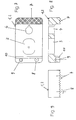
- Figures 7 to 9 show several views of a cheek, i.e. one half of the clamp, according to the previous figures.
- the sheet metal straightening clamp comprises two cheeks or half-clamps 1, 2 of a basically identical manufacture, one of them shown in Figs. 7 to 9.
- Each half-clamp 1, 2 is 'C'-shaped and there are two holes in the middle of the C, one of them is slotted 3 and extends towards the two peripheral branches of the 'C'; the pulling pin 6 is fitted and slides in this slot 3.
- the second hole 4, not slotted, houses a locking bolt 5.
- Each half-clamp has a knurled, toothed, or similar, gripping edge 7 at the top of one transverse branch of the 'C'-shaped part. The gripping edges 7 are used to grip the sheet metal above and below, where the clamp is to be fastened.
- each half-clamp has a plug 8 and a hole 9 respectively, used as a mutual reference to couple the two half-clamps 1 and 2.
- the half-clamp branch upper side inner edge is bevelled at 45°, thus forming a sloping surface 10 to engage a central double wedge.
- This wedge inserted between the two half-clamps, fastens the clamp to the metal sheet with a force proportional to the force applied to the bevels 10 by the double wedge.
- the locking bolt 5 passes through the holes 4 of the two half-clamps 1, 2 and on this bolt 5 a spring 11 can be inserted between the half-clamps 1, 2.
- the locking wedge especially the double locking wedge 12, is made of steel and moved by a pushing or pulling pin 6.
- the pushing or pulling pin 6 passes through the slots 3 of the two half-clamps 1, 2 and can slide transversally, that is perpendicular to the extension of the bevels 10 of the half-clamps 1, 2.
- the invention makes it possible to use the clamp with at least two different configurations, operating the clamp by pulling at a right angle or parallel to the gripping direction respectively, i.e. in the direction of engagement of the double wedge 12.
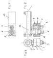
- Figures 1 to 3 show the sheet metal straightening clamp in a configuration where the pushing or pulling forces are applied parallel to the direction of engagement of the wedge 12 between the two half-clamps 1, 2.
- One end of the pulling pin 6 is equipped with couplings 15 to a pulling actuator (not shown), for example to the rod of a hydraulic jack.
- the couplings 15, shown on Figs. 1 to 3, consist of an adapter sleeve, the axis of which is parallel to the direction of engagement of the wedge 12; the adapter sleeve houses the rod of the hydraulic jack with its axis parallel to the sleeve axis.
- the sheet straightening clamp is positioned to grip the metal sheet when the locking bolt 5 is fastened. Force is then applied to the adapter sleeve 15 by means of a jack connected to the sheet metal straightening clamp; the force is directed towards the engagement of the wedge 12 between the two half-clamps 1 and 2. This pushing force is transferred to the double-cone wedge 12 which acts on the two 45° bevels 10 at the end of the two half-clamps 1, 2, thus generating a clamping force proportional to the pushing force. The pushing force can obviously be replaced by an appropriately directed pulling force.
- the second configuration does not require an adapter sleeve.
- Another adapting or transmitting wedge 16 is used instead of the sleeve, and is inserted between the locking bolt 5 and the pulling pin 6 or the double-cone wedge 12 on the same side, opposite the 45° bevels 10 of the half-clamps 1, 2.
- the adapting wedge consists of a slider with a forked end where the locking bolt 5 is engaged, whereas the fork's prong between the above locking bolt and the pulling pin 6, i.e. the front side of the double-cone wedge 12, is bevelled to an adapting or transmitting wedge 16 shape.
- the slider's opposite end is equipped with devices to engage an actuator, in particular, the rod of a hydraulic jack or similar.
- the slider moves transversely with respect to the sliding direction of the pulling pin 6 and the double-cone wedge 12; the adapting or transmitting wedge acts on the double-cone wedge 12, generating, like the previous configuration, a clamping force proportional to the pulling force applied.
- the pushing or pulling force is applied by coupling (keying) the pulling jack with the adapter sleeve 15 or the adapting or transmitting wedge 16.
- Figures 1 to 3 show a horizontal section, a front view and profile of the clamp, respectively, on a scale of 1:2.
- the above figures also show the locking bolt 5 passing through the two half-clamps or cheeks 1, 2, with the spring 11 inserted between them.
- the figures also show the double-cone locking wedge 12 fixed on the pulling pin 6, and the adapter sleeve 15 to couple the pulling devices (not shown), which forms an integral part with the same pulling pin 6.
- Figures 4 to 6 show a horizontal section, a front view and profile, respectively, of the first operating configuration on a scale of 1:2. These figures also show the locking bolt 5, the double-cone locking wedge 12 on the pulling pin 6 and the adapting or transmitting wedge 16 which acts on the double-cone wedge 12 when inserted between the latter and the locking bolt 5 transversally, i.e. perpendicular to the sliding movement of the double-cone wedge 12.
- Figures 7 to 9 show a horizontal section, a front view and profile, respectively, of one half-clamp or cheek 1, 2) on a full size scale.
- the figures also show the half-clamp's 1, 2 'C' shaped part, the knurled edge 7 for gripping the sheet metal, the slotted hole 4 for sliding the pulling pin 6, together with the double-cone wedge 12 and the hole 3 to pass through the locking bolt 5.
- the holes, the cooperating centering and mutual reference plugs 8, 9 on the two half-clamps 1, 2 and the 45° bevelled surface 10 on the inner edge of the 'C'-shaped part's transversal branch are also shown.
- the device concerned has been described and represented in an executive form simply for the sake of illustration and without any limitations to show its essential characteristics. It may therefore undergo many variations depending on industrial and commercial requirements, and may also use other systems and means, without losing its purpose.
Landscapes
- Engineering & Computer Science (AREA)
- Mechanical Engineering (AREA)
- Straightening Metal Sheet-Like Bodies (AREA)
- Vehicle Cleaning, Maintenance, Repair, Refitting, And Outriggers (AREA)
- Gripping Jigs, Holding Jigs, And Positioning Jigs (AREA)
Applications Claiming Priority (2)
| Application Number | Priority Date | Filing Date | Title |
|---|---|---|---|
| ITLI950003 IT239998Y1 (it) | 1995-04-06 | 1995-04-06 | Morsetto tendilamiera per riparazione di carrozzerie di autovetture |
| ITLI950003U | 1995-04-06 |
Publications (2)
| Publication Number | Publication Date |
|---|---|
| EP0736343A2 true EP0736343A2 (de) | 1996-10-09 |
| EP0736343A3 EP0736343A3 (de) | 1996-10-16 |
Family
ID=11355909
Family Applications (1)
| Application Number | Title | Priority Date | Filing Date |
|---|---|---|---|
| EP96105327A Withdrawn EP0736343A3 (de) | 1995-04-06 | 1996-04-03 | Blechspanneinrichtung, insbesondere für die Reparatur von Fahrzeugkarosserien oder dergleichen |
Country Status (2)
| Country | Link |
|---|---|
| EP (1) | EP0736343A3 (de) |
| IT (1) | IT239998Y1 (de) |
Cited By (1)
| Publication number | Priority date | Publication date | Assignee | Title |
|---|---|---|---|---|
| DE10211619A1 (de) * | 2002-03-15 | 2003-10-02 | Udo Tilch | Zugklemme zum Richten von Profilen und Blechen, insbesondere an Kraftfahrzeugen |
Family Cites Families (8)
| Publication number | Priority date | Publication date | Assignee | Title |
|---|---|---|---|---|
| US3355777A (en) * | 1966-03-30 | 1967-12-05 | Mojelski William | Tension actuated clamp |
| JPS5149092B2 (de) * | 1973-07-05 | 1976-12-24 | ||
| FR2314023A1 (fr) * | 1975-06-10 | 1977-01-07 | Wilmonda | Pince a auto-serrage perfectionnee |
| US3986746A (en) * | 1975-09-23 | 1976-10-19 | Guy-Chart Tools Limited | Clamp |
| US4037456A (en) * | 1976-07-15 | 1977-07-26 | Virgil Hinson | Auto body clamp |
| SE407531B (sv) * | 1976-08-17 | 1979-04-02 | Nike Hydraulik Ab | Dragklemma for anbringande pa platfalsar och liknande for overforing av dragkrafter |
| FR2519574A1 (fr) * | 1982-01-08 | 1983-07-18 | Celette Sa | Pince de traction |
| FR2682310B1 (fr) * | 1991-10-11 | 1994-01-14 | Blackhawk Sa | Pince de traction autoserrante pour le redressement d'elements de carrosserie deformes. |
-
1995
- 1995-04-06 IT ITLI950003 patent/IT239998Y1/it active
-
1996
- 1996-04-03 EP EP96105327A patent/EP0736343A3/de not_active Withdrawn
Cited By (2)
| Publication number | Priority date | Publication date | Assignee | Title |
|---|---|---|---|---|
| DE10211619A1 (de) * | 2002-03-15 | 2003-10-02 | Udo Tilch | Zugklemme zum Richten von Profilen und Blechen, insbesondere an Kraftfahrzeugen |
| DE10211619B4 (de) * | 2002-03-15 | 2004-09-02 | Udo Tilch | Zugklemme zum Richten eines Profils oder eines Blechs, insbesondere eines Karosserieteils eines unfallgeschädigten Kraftfahrzeuges |
Also Published As
| Publication number | Publication date |
|---|---|
| ITLI950003U1 (it) | 1996-10-06 |
| ITLI950003V0 (it) | 1995-04-06 |
| IT239998Y1 (it) | 2001-03-16 |
| EP0736343A3 (de) | 1996-10-16 |
Similar Documents
| Publication | Publication Date | Title |
|---|---|---|
| US4893393A (en) | Pipe fitting assembly tool | |
| JPH0547353B2 (de) | ||
| US6189190B1 (en) | System for the remote handling of equipment particularly adapted to elastic rings | |
| US11612991B2 (en) | Press device | |
| US5499800A (en) | Adjustable toggle action quick release locking bar clamp | |
| US5802690A (en) | Tool for reconnecting a fuel hose safety break away | |
| US4891877A (en) | Portable tool for compressing a fitting on a hose | |
| US5566438A (en) | Tool for reconnecting a fuel hose safety break away | |
| US4282737A (en) | Hand operated bending apparatus and method for metal bar, tubing and the like | |
| EP0736343A2 (de) | Blechspanneinrichtung, insbesondere für die Reparatur von Fahrzeugkarosserien oder dergleichen | |
| CA2484898A1 (en) | A clamp-type hand tool | |
| US20120297603A1 (en) | Hose Clamp Pliers | |
| EP1743741B1 (de) | Schraubstock für Rohre | |
| US5105646A (en) | Pipe bending plier | |
| CA1143266A (en) | Vehicle body clamp | |
| US3797094A (en) | Assembly tool | |
| US4769888A (en) | Method and apparatus for radiator recoring | |
| US3745638A (en) | Clamping device including lateral adjustment means thereon | |
| US5398535A (en) | Spreader clamp for automobile body repair and the like | |
| US3675897A (en) | Tool for drawing the ends of opposed members together | |
| GB2190618A (en) | Workbench and vice assembly | |
| US4550460A (en) | Air brake slack adjustment and measurement tools | |
| US5660069A (en) | Hands-free duct assembly tool | |
| CA1275833C (en) | Testing and adjusting tool for air brake cams | |
| US4930326A (en) | Manual hose end crimper |
Legal Events
| Date | Code | Title | Description |
|---|---|---|---|
| PUAI | Public reference made under article 153(3) epc to a published international application that has entered the european phase |
Free format text: ORIGINAL CODE: 0009012 |
|
| PUAL | Search report despatched |
Free format text: ORIGINAL CODE: 0009013 |
|
| AK | Designated contracting states |
Kind code of ref document: A2 Designated state(s): AT BE CH DE DK ES FR GB GR IE IT LI NL PT SE |
|
| AX | Request for extension of the european patent |
Free format text: SI PAYMENT 960404 |
|
| RAX | Requested extension states of the european patent have changed |
Free format text: SI PAYMENT 960404 |
|
| AK | Designated contracting states |
Kind code of ref document: A3 Designated state(s): AT BE CH DE DK ES FR GB GR IE IT LI NL PT SE |
|
| AX | Request for extension of the european patent |
Free format text: SI PAYMENT 960404 |
|
| 17P | Request for examination filed |
Effective date: 19970421 |
|
| STAA | Information on the status of an ep patent application or granted ep patent |
Free format text: STATUS: THE APPLICATION IS DEEMED TO BE WITHDRAWN |
|
| 18D | Application deemed to be withdrawn |
Effective date: 19991103 |