EP0736352A2 - Dispositif pour ajuster l'angle d'inclinaison et le mouvement orbital d'une lame de scie à mouvement alternatif - Google Patents
Dispositif pour ajuster l'angle d'inclinaison et le mouvement orbital d'une lame de scie à mouvement alternatif Download PDFInfo
- Publication number
- EP0736352A2 EP0736352A2 EP96200927A EP96200927A EP0736352A2 EP 0736352 A2 EP0736352 A2 EP 0736352A2 EP 96200927 A EP96200927 A EP 96200927A EP 96200927 A EP96200927 A EP 96200927A EP 0736352 A2 EP0736352 A2 EP 0736352A2
- Authority
- EP
- European Patent Office
- Prior art keywords
- blade
- blade clamp
- drive block
- arcuate cam
- cam follower
- Prior art date
- Legal status (The legal status is an assumption and is not a legal conclusion. Google has not performed a legal analysis and makes no representation as to the accuracy of the status listed.)
- Withdrawn
Links
Images

Classifications
-
- B—PERFORMING OPERATIONS; TRANSPORTING
- B23—MACHINE TOOLS; METAL-WORKING NOT OTHERWISE PROVIDED FOR
- B23D—PLANING; SLOTTING; SHEARING; BROACHING; SAWING; FILING; SCRAPING; LIKE OPERATIONS FOR WORKING METAL BY REMOVING MATERIAL, NOT OTHERWISE PROVIDED FOR
- B23D49/00—Machines or devices for sawing with straight reciprocating saw blades, e.g. hacksaws
- B23D49/10—Hand-held or hand-operated sawing devices with straight saw blades
- B23D49/16—Hand-held or hand-operated sawing devices with straight saw blades actuated by electric or magnetic power or prime movers
- B23D49/162—Pad sawing devices
- B23D49/165—Pad sawing devices with means to move the saw blades in an orbital path
-
- Y—GENERAL TAGGING OF NEW TECHNOLOGICAL DEVELOPMENTS; GENERAL TAGGING OF CROSS-SECTIONAL TECHNOLOGIES SPANNING OVER SEVERAL SECTIONS OF THE IPC; TECHNICAL SUBJECTS COVERED BY FORMER USPC CROSS-REFERENCE ART COLLECTIONS [XRACs] AND DIGESTS
- Y10—TECHNICAL SUBJECTS COVERED BY FORMER USPC
- Y10T—TECHNICAL SUBJECTS COVERED BY FORMER US CLASSIFICATION
- Y10T83/00—Cutting
- Y10T83/869—Means to drive or to guide tool
- Y10T83/8874—Uniplanar compound motion
Definitions
- the present invention relates to power operated, reciprocating saws, such as so-called recipro saws and jig saws. More particularly, the present invention relates to mechanism for imparting an orbital movement to the working portion of the saw blade.
- the present invention provides a simplified but effective mechanism for imparting orbital movement to the working end of a reciprocating saw blade. Further, the invention provides means for deactivating the orbital mechanism and permitting the saw blade to be fixed in a desired angle of inclination or cant with respect to the reciprocating plunger of the power tool.
- a primary object of the invention is the provision of a new orbital mechanism for a reciprocating saw blade.
- Another object of the invention is the provision of an orbital mechanism for a reciprocating saw which requires a minimum of moving parts by utilizing the frictional engagement between the saw blade and the work to actuate the orbital mechanism.
- Still another object of the present invention is the provision of an orbital mechanism for a reciprocating saw blade wherein a portion of the orbital mechanism serves to mount the saw blade.
- Yet another object of the present invention is the provision of an orbital mechanism for a reciprocating saw blade wherein such mechanism may be deactivated thereby permitting the blade to be adjusted to a desired angle of inclination or cant with respect to the reciprocating plunger.
- Another object of the present invention is the provision of an orbital mechanism for a reciprocating saw which can be used as an attachment to convert a reciprocating saw without orbital action into a reciprocating saw with orbital action.
- a reciprocating power saw such as a recipro saw
- a housing or casing 12 which only the nose portion of the tool is shown in Figure 1. Tools of this type are well-known in the art and require no detailed description.
- the housing 12 mounts a plurality of guide bars 14. It will be understood that these guide bars define a rectilinear guideway for slidably receiving a drive block, generally designated 16.
- Piston rod 18 has one end thereof connected to the drive block 16.
- the power tool 10 includes suitable powered means (not shown) for imparting reciprocal movement to the piston rod 18 and thus to the drive block 16.
- the drive block 16 is in the form of a block 20 having a recess 22 in one side thereof thus defining shoulders 24 and 26.
- the drive block 20 includes a step-shaped cavity or recess 28.
- the cavity 28 defines first, second and third arcuate cam surfaces 30, 32 and 34, respectively. It will be understood that the radii of these arcuate cam surfaces have a common center point.
- the cavity 28 includes an arcuate stop surface 36 between the arcuate cam surfaces 32 and 34.
- the recess 28 includes a further stop surface 38.
- the arcuate cam surface 30 is interrupted by a semi-cylindrical recess 40, the purpose of which will be explained below.
- the drive mechanism also includes a plate 42 as seen in Figures 6 and 7. This plate is received within the recess 22 of the block 20.
- the plate 42 may be secured to the block 20 by a fastener (not shown) received within apertures 44 and 46 formed respectively in the block 20 and plate 42. It will be apparent that when the plate 42 is secured in the recess 22, the plate serves to close the step-shaped recess 22, such that the latter recess opens only at the forward end of the drive block.
- the drive block 16 or plate 42 could be formed as an integral part of the plunger 18.
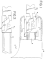
- the orbital mechanism of the present invention includes a blade clamp, generally designated 50, and best shown in Figure 3.
- the blade clamp includes a body portion 52 and an integral cam follower portion 54.
- the body portion includes one or more apertures or recesses to facilitate mounting a saw blade 56 (not shown in Figure 3) of a known type.
- the cam follower portion 54 includes first, second and third cam follower surfaces 58, 60 and 62, respectively. It will further be noted that the step-shaped cam follower portion of the blade clamp includes a first stop portion 64 and a second stop surface 66 disposed between the cam follower surfaces 60 and 62. It will be understood that the radii forming the cam surfaces 58, 60 and 62 are co-planar with the plane of the blade and have a common center. These radii could also be in a plane that is parallel to and offset from the plane of the blade.
- step-shaped cam follower portion 54 of the blade clamp is received within the step-shaped recess 28 formed in the cam block 16, the latter being defined by the block 20 and the plate 42.
- various cam surfaces formed in the recess 28 are complimentary in shape with the cam follower surfaces on the step-shaped cam follower portion 54 of the blade clamp 50.
- the radius of the cam surface 30 is substantially the same as the radius of the cam follower surface 58 thus permitting smooth sliding engagement between these two surfaces.
- the radius of the cam surface 32 is substantially the same as the radius of the cam follower surface 60, again permitting smooth sliding engagement between these two surfaces.
- the radius of the cam surface 34 is substantially the same as the radius of the cam follower surface 62 to permit smooth sliding engagement between these surfaces.
- the cam follower portion 54 is provided with a pair of semi-cylindrical recesses 70 and 72; these surfaces open into the cam follower surface 58.
- a cylindrical opening is formed for receipt of a locking pin 74 ( Figure 2).
- the blade clamp may be locked to the drive block thereby deactivating the orbital mechanism because relative movement between the cam follower portion 54 and the step-shaped recess 28 will no longer be permitted.
- the provision of the two semi-cylindrical recesses 70, 72 permit the blade to be locked in two different cant positions relative to the axis of reciprocation of the drive block 60.
- the orbital mechanism of the present invention readily lends itself to the establishment of an adjustable cant mechanism for the blade.
- the mechanism of the present invention is particularly unique in that it requires an absolute minimum of parts. As concerns simplicity of parts and operation, it is noted that the blade clamp 50 is solely mounted by reason of the interengagement between the cam follower portion 54 and the recess 28 in the drive block.
- the orbital and adjustable cant mechanism is shown as being an integral part of the power tool 10. It will be understood that the present invention may be formed as an attachment to convert a reciprocating saw without orbital action into a reciprocating saw with the orbital and adjustable cant mechanism.
Landscapes
- Engineering & Computer Science (AREA)
- Mechanical Engineering (AREA)
- Sawing (AREA)
Applications Claiming Priority (2)
| Application Number | Priority Date | Filing Date | Title |
|---|---|---|---|
| US08/417,931 US5479711A (en) | 1995-04-06 | 1995-04-06 | Orbital and adjustable cant mechanism for reciprocating saws |
| US417931 | 1995-04-06 |
Publications (2)
| Publication Number | Publication Date |
|---|---|
| EP0736352A2 true EP0736352A2 (fr) | 1996-10-09 |
| EP0736352A3 EP0736352A3 (fr) | 1998-08-19 |
Family
ID=23655943
Family Applications (1)
| Application Number | Title | Priority Date | Filing Date |
|---|---|---|---|
| EP96200927A Withdrawn EP0736352A3 (fr) | 1995-04-06 | 1996-04-04 | Dispositif pour ajuster l'angle d'inclinaison et le mouvement orbital d'une lame de scie à mouvement alternatif |
Country Status (2)
| Country | Link |
|---|---|
| US (1) | US5479711A (fr) |
| EP (1) | EP0736352A3 (fr) |
Families Citing this family (13)
| Publication number | Priority date | Publication date | Assignee | Title |
|---|---|---|---|---|
| DE4427875C1 (de) * | 1994-08-06 | 1996-01-04 | Palitex Project Co Gmbh | Verfahren zur Herstellung eines Zwirns in einem integrierten Spinn-Zwirnprozess nach dem Doppeldrahtprinzip sowie Vorrichtung zur Durchführung des Verfahrens |
| US6508151B1 (en) | 1996-08-19 | 2003-01-21 | Milwaukee Electric Tool Corporation | Reciprocating saw with rocker motion |
| US6829831B1 (en) | 1996-08-19 | 2004-12-14 | Milwaukee Electric Tool Corporation | Reciprocating saw with rocker motion |
| US6233833B1 (en) * | 1997-06-05 | 2001-05-22 | Black & Decker Inc. | Reciprocating saw with clamp for receiving blade in multiple orientations |
| US7127973B2 (en) * | 1998-02-09 | 2006-10-31 | Milwaukee Electric Tool Corporation | Reciprocating saw |
| US6249979B1 (en) * | 1998-08-13 | 2001-06-26 | Milwaukee Electric Tool Corporation | Orbital reciprocating saw |
| JP4147673B2 (ja) | 1999-03-12 | 2008-09-10 | 日立工機株式会社 | セーバソー |
| US6634107B2 (en) | 1999-03-12 | 2003-10-21 | Hitachi Koki Co., Ltd. | Cutting mechanism for a saber saw |
| GB2393934A (en) * | 2002-10-07 | 2004-04-14 | Black & Decker Inc | A reciprocating saw with two eccentrics |
| DE102004022361B4 (de) * | 2004-05-06 | 2007-06-06 | Hilti Ag | Hubsägewerkzeug |
| US8230607B2 (en) | 2008-05-09 | 2012-07-31 | Milwaukee Electric Tool Corporation | Keyless blade clamp for a power tool |
| US20170136635A1 (en) * | 2015-11-16 | 2017-05-18 | Thomas R. Johnston | Aircraft egress and multifunction tool |
| WO2019237111A1 (fr) * | 2018-06-08 | 2019-12-12 | Urschel Laboratories, Inc. | Couteaux et ensembles couteaux destinés à des machines à trancher et machines à trancher dotées de ces derniers |
Family Cites Families (13)
| Publication number | Priority date | Publication date | Assignee | Title |
|---|---|---|---|---|
| US2621685A (en) * | 1949-01-17 | 1952-12-16 | Tri Saw Corp | Hand carried power tool |
| FR1059119A (fr) * | 1954-03-26 | 1954-03-23 | Rcs Engineering Corp | Perfectionnements aux dispositifs à mouvement alternatif pour scies |
| US2946358A (en) * | 1958-11-28 | 1960-07-26 | American Lincoln Corp | Saber saw |
| GB999746A (en) * | 1963-08-01 | 1965-07-28 | Wickman Wimet Ltd | Metal cutting tools |
| US3942251A (en) * | 1971-09-17 | 1976-03-09 | Rockwell International Corporation | Saber saw |
| US3802079A (en) * | 1972-05-15 | 1974-04-09 | Stanley Works | Saw blade holder for portable reciprocating saw |
| US3977289A (en) * | 1973-01-08 | 1976-08-31 | National Research Development Corporation | Saws and blades therefor |
| US3945120A (en) * | 1974-04-25 | 1976-03-23 | Milwaukee Electric Tool Corporation | Vibration dampening and heat sink mechanism for a reciprocating power saw |
| DE2655583C2 (de) * | 1976-12-08 | 1982-07-01 | Black & Decker, Inc., 19711 Newark, Del. | Stichsäge |
| US4379362A (en) * | 1979-06-18 | 1983-04-12 | Getts Sidney Arthur | Motion conversion mechanism |
| US4550501A (en) * | 1984-01-23 | 1985-11-05 | Black & Decker Inc. | Orbital-action reciprocating power saw |
| US4628605A (en) * | 1985-06-10 | 1986-12-16 | Porter-Cable Corporation | Orbital bayonet saw |
| US5212887A (en) * | 1992-03-18 | 1993-05-25 | S-B Power Tool Company | Counterbalanced orbital drive mechanism for saws and the like |
-
1995
- 1995-04-06 US US08/417,931 patent/US5479711A/en not_active Expired - Lifetime
-
1996
- 1996-04-04 EP EP96200927A patent/EP0736352A3/fr not_active Withdrawn
Also Published As
| Publication number | Publication date |
|---|---|
| EP0736352A3 (fr) | 1998-08-19 |
| US5479711A (en) | 1996-01-02 |
Similar Documents
| Publication | Publication Date | Title |
|---|---|---|
| US5479711A (en) | Orbital and adjustable cant mechanism for reciprocating saws | |
| EP0748665B1 (fr) | Un moyen d'abloquage pour lame de scie alternative | |
| US7325315B2 (en) | Clamping arrangement for receiving a saw blade in multiple orientations | |
| US7003888B2 (en) | Clamping arrangement for receiving a saw blade | |
| CA1176955A (fr) | Scie mecanique a chantourner et son porte-lame | |
| US6920694B2 (en) | Saw with a tool guidance mechanism with guide elements adjustable to the tool size | |
| US6851193B2 (en) | Reciprocating saw | |
| US4451026A (en) | Clamping device | |
| US5473820A (en) | Power-operated sword saw | |
| US6009627A (en) | Saw blade clamping arrangement for a power tool | |
| WO2000021707A8 (fr) | Scie alternative | |
| EP1188505A3 (fr) | Outils de coupe à mouvement de va-et-vient | |
| GB2178689A (en) | A clamp for single-handed operation | |
| US6295736B1 (en) | Blade ejection mechanism for a saw blade clamping arrangement of a power tool | |
| EP0949032A2 (fr) | Dispositif de serrage d'une lame de scie pour outil motorisé | |
| US4566190A (en) | Reciprocating blade cutting device | |
| US2866485A (en) | Power tools | |
| US5097578A (en) | File or rasp for a power tool | |
| GB2177339A (en) | Nibbling tool | |
| EP1785212A3 (fr) | Scie alternative | |
| US5044080A (en) | Hand held nibbling machine | |
| US3787970A (en) | Bevelling tool | |
| US3785052A (en) | Heavy duty nibbler | |
| RU2117564C1 (ru) | Устройство для зажима заготовок | |
| SU1458135A1 (ru) | Рабочий орган металлорежущего станка |
Legal Events
| Date | Code | Title | Description |
|---|---|---|---|
| PUAI | Public reference made under article 153(3) epc to a published international application that has entered the european phase |
Free format text: ORIGINAL CODE: 0009012 |
|
| AK | Designated contracting states |
Kind code of ref document: A2 Designated state(s): DE ES FR GB IT |
|
| PUAL | Search report despatched |
Free format text: ORIGINAL CODE: 0009013 |
|
| AK | Designated contracting states |
Kind code of ref document: A3 Designated state(s): DE ES FR GB IT |
|
| 17P | Request for examination filed |
Effective date: 19990219 |
|
| 17Q | First examination report despatched |
Effective date: 20010227 |
|
| GRAG | Despatch of communication of intention to grant |
Free format text: ORIGINAL CODE: EPIDOS AGRA |
|
| GRAG | Despatch of communication of intention to grant |
Free format text: ORIGINAL CODE: EPIDOS AGRA |
|
| GRAH | Despatch of communication of intention to grant a patent |
Free format text: ORIGINAL CODE: EPIDOS IGRA |
|
| STAA | Information on the status of an ep patent application or granted ep patent |
Free format text: STATUS: THE APPLICATION IS DEEMED TO BE WITHDRAWN |
|
| 18D | Application deemed to be withdrawn |
Effective date: 20020430 |