EP0736368A1 - Procédé pour le réglage de la fréquence de l'operation d'un système à vibration orbital du soudage - Google Patents
Procédé pour le réglage de la fréquence de l'operation d'un système à vibration orbital du soudage Download PDFInfo
- Publication number
- EP0736368A1 EP0736368A1 EP96105639A EP96105639A EP0736368A1 EP 0736368 A1 EP0736368 A1 EP 0736368A1 EP 96105639 A EP96105639 A EP 96105639A EP 96105639 A EP96105639 A EP 96105639A EP 0736368 A1 EP0736368 A1 EP 0736368A1
- Authority
- EP
- European Patent Office
- Prior art keywords
- frequency
- shape
- oscillation
- working frequency
- vibration
- Prior art date
- Legal status (The legal status is an assumption and is not a legal conclusion. Google has not performed a legal analysis and makes no representation as to the accuracy of the status listed.)
- Granted
Links
- 238000003466 welding Methods 0.000 title claims abstract description 20
- 238000000034 method Methods 0.000 title claims description 17
- 230000010355 oscillation Effects 0.000 claims abstract description 15
- 238000010586 diagram Methods 0.000 description 2
- 238000013461 design Methods 0.000 description 1
- 238000011161 development Methods 0.000 description 1
- 230000018109 developmental process Effects 0.000 description 1
- 238000005304 joining Methods 0.000 description 1
- 238000004519 manufacturing process Methods 0.000 description 1
- 238000005259 measurement Methods 0.000 description 1
- 238000005457 optimization Methods 0.000 description 1
- 230000001105 regulatory effect Effects 0.000 description 1
- 238000012546 transfer Methods 0.000 description 1
- 230000007704 transition Effects 0.000 description 1
Images

Classifications
-
- B—PERFORMING OPERATIONS; TRANSPORTING
- B29—WORKING OF PLASTICS; WORKING OF SUBSTANCES IN A PLASTIC STATE IN GENERAL
- B29C—SHAPING OR JOINING OF PLASTICS; SHAPING OF MATERIAL IN A PLASTIC STATE, NOT OTHERWISE PROVIDED FOR; AFTER-TREATMENT OF THE SHAPED PRODUCTS, e.g. REPAIRING
- B29C65/00—Joining or sealing of preformed parts, e.g. welding of plastics materials; Apparatus therefor
- B29C65/02—Joining or sealing of preformed parts, e.g. welding of plastics materials; Apparatus therefor by heating, with or without pressure
- B29C65/06—Joining or sealing of preformed parts, e.g. welding of plastics materials; Apparatus therefor by heating, with or without pressure using friction, e.g. spin welding
- B29C65/0609—Joining or sealing of preformed parts, e.g. welding of plastics materials; Apparatus therefor by heating, with or without pressure using friction, e.g. spin welding characterised by the movement of the parts to be joined
- B29C65/0627—Angular, i.e. torsional
-
- B—PERFORMING OPERATIONS; TRANSPORTING
- B23—MACHINE TOOLS; METAL-WORKING NOT OTHERWISE PROVIDED FOR
- B23K—SOLDERING OR UNSOLDERING; WELDING; CLADDING OR PLATING BY SOLDERING OR WELDING; CUTTING BY APPLYING HEAT LOCALLY, e.g. FLAME CUTTING; WORKING BY LASER BEAM
- B23K20/00—Non-electric welding by applying impact or other pressure, with or without the application of heat, e.g. cladding or plating
- B23K20/12—Non-electric welding by applying impact or other pressure, with or without the application of heat, e.g. cladding or plating the heat being generated by friction; Friction welding
- B23K20/121—Control circuits therefor
-
- B—PERFORMING OPERATIONS; TRANSPORTING
- B29—WORKING OF PLASTICS; WORKING OF SUBSTANCES IN A PLASTIC STATE IN GENERAL
- B29C—SHAPING OR JOINING OF PLASTICS; SHAPING OF MATERIAL IN A PLASTIC STATE, NOT OTHERWISE PROVIDED FOR; AFTER-TREATMENT OF THE SHAPED PRODUCTS, e.g. REPAIRING
- B29C66/00—General aspects of processes or apparatus for joining preformed parts
- B29C66/90—Measuring or controlling the joining process
- B29C66/95—Measuring or controlling the joining process by measuring or controlling specific variables not covered by groups B29C66/91 - B29C66/94
- B29C66/951—Measuring or controlling the joining process by measuring or controlling specific variables not covered by groups B29C66/91 - B29C66/94 by measuring or controlling the vibration frequency and/or the vibration amplitude of vibrating joining tools, e.g. of ultrasonic welding tools
- B29C66/9512—Measuring or controlling the joining process by measuring or controlling specific variables not covered by groups B29C66/91 - B29C66/94 by measuring or controlling the vibration frequency and/or the vibration amplitude of vibrating joining tools, e.g. of ultrasonic welding tools by controlling their vibration frequency
Definitions
- the invention relates to a method for setting the working frequency of an orbital vibration welding system according to the preamble of claim 1 and a device for performing the method.
- orbital vibration welding systems In contrast to linear vibration welding systems, orbital vibration welding systems have no pronounced direction of vibration. Due to the system-related design, the orbital systems have a vibration level available. Depending on manufacturing tolerances and mass asymmetries, there are several, generally two, preferred vibration directions. Different resonance frequencies correspond to these different directions of vibration. In practice, this results in two resonance frequencies in the case of rectangular geometries, in which the oscillating head tends to oscillate linearly in the direction of the longitudinal or transverse axis. In the area between the two resonance frequencies there is a transition area in which the oscillating head changes the direction of movement from linear transverse to linear longitudinal oscillation and thereby oscillates elliptically or roundly.
- the advantage of the orbital oscillation system lies in the possibility of round or at least elliptical oscillation.
- the best welding results and / or the shortest welding times result due to the harmonic movement (no oscillation head standstill at the reversal point, the welding speed is largely constant in terms of amount). Due to the harmonic movement, the energy transfer is generally higher and more uniform in orbital systems than in linear systems.
- the invention has for its object to provide a method with which an optimal working frequency on the orbital vibration welding system can be set in a simple manner.
- a method is specified with which a new optimum working frequency is to be set each time the tool of the orbital vibration welding machine is changed and / or when welding workpieces with a different geometry, that is to say with different applications.
- the movement is adjusted in three stages. First, the entire preselected frequency band is traversed, starting with the lowest frequency, the absolute current minimum or minimum power being sought in the resonant circuit. This corresponds to the strongest pronounced resonance frequency, which i.a. but does not correspond to a circular movement.
- the optimization criterion is the ratio of the small to the large semiaxis of the elliptical orbit. If this ratio becomes one, the perfect circular shape is found. Will the relationship however, worse than at the beginning of the measurement, the best possible circular path cannot be found for higher frequencies, and the search is carried out again for lower frequencies. The search then results in the best possible circular path within the specified frequency range.
- the circular orbit is called the best possible, in which the amounts of the large and small half axis of the ellipse are closest to each other. Depending on the application and mass, this can also be an elongated ellipse or a straight line. The system then sets this best possible frequency.
- the system checks whether the frequency found leads to a stable movement or whether the movement changes (staggering of the circular path, changing the radius, etc.). If it is not stable, the frequency of the current minimum is output and saved as the working frequency.
- the best possible circular shape can be an unfavorable movement.
- the search criteria are changed, ie instead of the best possible circular shape to look, one selects a movement with a correspondingly different shape (e.g. elongated ellipse or linear oscillating movement) and the search process takes place under no load or under load under the correspondingly changed search criteria.
- an optimum working frequency can be found for each joining geometry, which generally produces a circular or elliptical vibration geometry, but which can also represent an elongated elliptical shape or even a straight line.
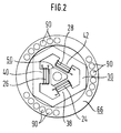
- a ⁇ -controller or a processor 1 of similar performance is used as the intelligent unit. This receives the signal from the current or power meter via an amplifier unit 2, with which the coil current of the electromagnetic drive system for the orbital welding machine (not shown) is measured.
- An exemplary embodiment for such a vibration welding machine is known from EP 0 504 494 A2. From this it is also known to set the working frequency to the resonance frequency of the system. For this purpose, the phase angle between voltage and current of the electromagnetic drive is determined, which is zero for the resonance state.
- the current signal is preferably taken directly from the drive coils of the electromagnetic drive in order in this way to determine the power minimum as directly as possible.
- the form of movement is detected by one or more sensors, which can record the movement in a direction-sensitive manner. This can be done, for example, by using two accelerometers, which are 90 ° to each other in the plane of movement happen.
- the processor determines the path of the vibration system from these two signals. In the case of a circular path, both signals have the same magnitude and are phase-shifted by 90 °. These signals are referred to as analog inputs 3 in the block diagram. These signals are processed in an input filter and transferred to processor 1.
- the processor issues the commands for driving through the frequency, the vibration amplitude to be used and / or after adjustment for the operating frequency found, via an output 5 to the frequency converter (not shown), which drives the electromagnetic drive of the oscillating head.
- the target frequency for the drive is transferred as a voltage signal.
- the processor is connected to a machine control via digital inputs and outputs 6 and 7, e.g. a PLC.
- a machine control via digital inputs and outputs 6 and 7, e.g. a PLC.
- the parameters e.g. the parameters (frequency range, search method, etc.) to be entered via the machine control units.
- the parameters found are transferred to the PLC, which controls the machine with them, or these parameters can be read out and processed further. Ready and error messages are also transferred to the PLC.
- the tuning system which is set up separately from the PLC, also enables the machine to be controlled and regulated purely manually or via the PLC without adjustment. In this case, the controller is switched to passive via a digital input.
- the direction-sensitive sensors used or one of them can also be used to control the amplitude during the tuning and welding process to be used.
- a separate sensor system for the amplitude control is not required.
Landscapes
- Engineering & Computer Science (AREA)
- Mechanical Engineering (AREA)
- Lining Or Joining Of Plastics Or The Like (AREA)
- Pressure Welding/Diffusion-Bonding (AREA)
- Apparatuses For Generation Of Mechanical Vibrations (AREA)
- Butt Welding And Welding Of Specific Article (AREA)
Applications Claiming Priority (2)
| Application Number | Priority Date | Filing Date | Title |
|---|---|---|---|
| DE19512820 | 1995-04-05 | ||
| DE19512820A DE19512820B4 (de) | 1995-04-05 | 1995-04-05 | Verfahren und Vorrichtung zum Einstellen der Arbeitsfrequenz eines Orbitalvibrationsschweißsystems |
Publications (2)
| Publication Number | Publication Date |
|---|---|
| EP0736368A1 true EP0736368A1 (fr) | 1996-10-09 |
| EP0736368B1 EP0736368B1 (fr) | 2002-08-21 |
Family
ID=7758889
Family Applications (1)
| Application Number | Title | Priority Date | Filing Date |
|---|---|---|---|
| EP96105639A Expired - Lifetime EP0736368B1 (fr) | 1995-04-05 | 1996-04-09 | Procédé pour le réglage de la fréquence de l'operation d'un système à vibration orbital du soudage |
Country Status (5)
| Country | Link |
|---|---|
| US (1) | US5795419A (fr) |
| EP (1) | EP0736368B1 (fr) |
| JP (1) | JP3875307B2 (fr) |
| DE (2) | DE19512820B4 (fr) |
| ES (1) | ES2178688T3 (fr) |
Cited By (1)
| Publication number | Priority date | Publication date | Assignee | Title |
|---|---|---|---|---|
| EP1301331A4 (fr) * | 2000-06-16 | 2007-10-03 | Sonics & Materials Inc | Dispositif de commande d'energie pour une soudeuse a vibration |
Families Citing this family (11)
| Publication number | Priority date | Publication date | Assignee | Title |
|---|---|---|---|---|
| US6091215A (en) * | 1998-06-02 | 2000-07-18 | Switched Reluctance Drives Limited | Trajectory controller |
| US6731083B2 (en) | 1998-06-02 | 2004-05-04 | Switched Reluctance Drives, Ltd. | Flux feedback control system |
| US6404154B2 (en) * | 1998-06-02 | 2002-06-11 | Emerson Electric Co. | Force control system |
| JP3812652B2 (ja) * | 2001-12-28 | 2006-08-23 | Ykk株式会社 | ファスナーテープに対する補強テープ片の超音波溶着方法及び溶着装置 |
| DE10347345B4 (de) * | 2003-10-11 | 2006-06-14 | Kln Ultraschall Gmbh | Verfahren und Anordnung zum Reibungsschweißen |
| US7810699B1 (en) * | 2009-04-22 | 2010-10-12 | Gm Global Technology Operations, Inc. | Method and system for optimized vibration welding |
| SG177745A1 (en) * | 2009-08-12 | 2012-02-28 | Kulicke & Soffa Ind Inc | Ultrasonic transducers for wire bonding and methods of forming wire bonds using ultrasonic transducers |
| US8245748B2 (en) * | 2010-07-14 | 2012-08-21 | Dukane Corporation | Vibration welding system |
| US9688017B2 (en) | 2013-05-14 | 2017-06-27 | Dukan IAS, LLC | Vibration welders with high frequency vibration, position motion control, and delayed weld motion |
| DE202014105435U1 (de) * | 2014-11-12 | 2016-01-25 | Kuka Systems Gmbh | Pressschweißvorrichtung |
| DE202014105434U1 (de) * | 2014-11-12 | 2016-02-15 | Kuka Systems Gmbh | Pressschweißvorrichtung |
Citations (4)
| Publication number | Priority date | Publication date | Assignee | Title |
|---|---|---|---|---|
| US4247346A (en) * | 1977-05-12 | 1981-01-27 | Asahi Kasei Kogyo Kabushiki Kaisha | Friction welding apparatus |
| EP0340671A2 (fr) * | 1988-05-03 | 1989-11-08 | BRANSON ULTRASCHALL Niederlassung der EMERSON TECHNOLOGIES GmbH & CO. | Procédé et appareil pour la commande des paramètres d'une machine de soudage par friction |
| EP0481125A2 (fr) * | 1990-01-18 | 1992-04-22 | BRANSON ULTRASCHALL Niederlassung der EMERSON TECHNOLOGIES GmbH & CO. | Dispositif d'ajustement d'un paramètre d'une machine de sondage par friction |
| EP0504494A2 (fr) * | 1990-12-27 | 1992-09-23 | Hydroacoustics Inc. | Appareil de soudage par friction comportant un dispositif d'entraînement produisant un mouvement orbital |
Family Cites Families (7)
| Publication number | Priority date | Publication date | Assignee | Title |
|---|---|---|---|---|
| US4606490A (en) * | 1982-08-24 | 1986-08-19 | Asm Assembly Automation Limited | Apparatus and method for automatic evaluation of a bond created by an ultrasonic transducer |
| US4631685A (en) * | 1984-12-07 | 1986-12-23 | General Motors Corporation | Method and apparatus for ultrasonic plastic forming and joining |
| US4844320A (en) * | 1987-02-17 | 1989-07-04 | General Electric Company | Control system and method for vibration welding |
| ATE117611T1 (de) * | 1991-02-15 | 1995-02-15 | Esec Sa | Verfahren und einrichtung zur messung der schwingungsamplitude an einem energietransducer. |
| DE69216761T2 (de) * | 1991-10-30 | 1997-07-03 | F & K Delvotev Bondtechgmbh | Steuerungssystem |
| GB2270868B (en) * | 1992-09-08 | 1995-03-22 | Emhart Inc | Control system |
| DE4211279A1 (de) * | 1992-04-03 | 1993-10-07 | Branson Ultraschall | Vibrationsschweißmaschine |
-
1995
- 1995-04-05 DE DE19512820A patent/DE19512820B4/de not_active Expired - Fee Related
-
1996
- 1996-04-05 US US08/628,851 patent/US5795419A/en not_active Expired - Fee Related
- 1996-04-05 JP JP08373396A patent/JP3875307B2/ja not_active Expired - Fee Related
- 1996-04-09 ES ES96105639T patent/ES2178688T3/es not_active Expired - Lifetime
- 1996-04-09 EP EP96105639A patent/EP0736368B1/fr not_active Expired - Lifetime
- 1996-04-09 DE DE59609565T patent/DE59609565D1/de not_active Expired - Fee Related
Patent Citations (4)
| Publication number | Priority date | Publication date | Assignee | Title |
|---|---|---|---|---|
| US4247346A (en) * | 1977-05-12 | 1981-01-27 | Asahi Kasei Kogyo Kabushiki Kaisha | Friction welding apparatus |
| EP0340671A2 (fr) * | 1988-05-03 | 1989-11-08 | BRANSON ULTRASCHALL Niederlassung der EMERSON TECHNOLOGIES GmbH & CO. | Procédé et appareil pour la commande des paramètres d'une machine de soudage par friction |
| EP0481125A2 (fr) * | 1990-01-18 | 1992-04-22 | BRANSON ULTRASCHALL Niederlassung der EMERSON TECHNOLOGIES GmbH & CO. | Dispositif d'ajustement d'un paramètre d'une machine de sondage par friction |
| EP0504494A2 (fr) * | 1990-12-27 | 1992-09-23 | Hydroacoustics Inc. | Appareil de soudage par friction comportant un dispositif d'entraînement produisant un mouvement orbital |
Cited By (1)
| Publication number | Priority date | Publication date | Assignee | Title |
|---|---|---|---|---|
| EP1301331A4 (fr) * | 2000-06-16 | 2007-10-03 | Sonics & Materials Inc | Dispositif de commande d'energie pour une soudeuse a vibration |
Also Published As
| Publication number | Publication date |
|---|---|
| EP0736368B1 (fr) | 2002-08-21 |
| JP3875307B2 (ja) | 2007-01-31 |
| US5795419A (en) | 1998-08-18 |
| JPH08294969A (ja) | 1996-11-12 |
| ES2178688T3 (es) | 2003-01-01 |
| DE19512820A1 (de) | 1996-10-10 |
| DE19512820B4 (de) | 2005-11-03 |
| DE59609565D1 (de) | 2002-09-26 |
Similar Documents
| Publication | Publication Date | Title |
|---|---|---|
| DE60100372T2 (de) | Steuervorrichtung für eine Maschine | |
| DE60110673T2 (de) | Servosteuerung | |
| DE102009058443B4 (de) | Trägheitsschätzsteuerungseinrichtung und Steuerungssystem | |
| DE19512820B4 (de) | Verfahren und Vorrichtung zum Einstellen der Arbeitsfrequenz eines Orbitalvibrationsschweißsystems | |
| DE102005015810B4 (de) | Bearbeitungszeit-Berechnungsvorrichtung | |
| DE102011018536B4 (de) | Numerische Steuerung mit einer Oszillationsvorgangsfunktion, die im Stande ist, die Geschwindigkeit in einem optionalen Abschnitt zu ändern | |
| DE102007008669A1 (de) | Verfahren zur Bestimmung und/oder Überwachung einer Prozessgröße eines Mediums und entsprechende Vorrichtung | |
| DE102019213924B4 (de) | Motorsteuervorrichtung | |
| DE10043636A1 (de) | Verfahren und Schaltungsanordnung zur Erzeugung von Lagesollwerten für einen Lageregelkreis einer numerisch bahngesteuerten Maschine | |
| EP0896263B1 (fr) | Procédé et circuit pour déterminer les paramètres optimaux pour contrôle de vitesse de rotation | |
| DE3433499C2 (de) | Pendeldrucker | |
| EP0490869B1 (fr) | Circuit de réglage pour la régulation de l'impédance d'un four à arc | |
| DE69613547T2 (de) | Filterung mit konstanter Verzögerung für synchronisierte Mehrachsenantriebe | |
| EP3990990B1 (fr) | Procédé et dispositif de commande d'une unité d'outil ultrasonique pour l'usinage par enlèvement de copeaux sur une machine-outil | |
| WO2018108352A1 (fr) | Machine-outil pour l'usinage d'une pièce par enlèvement de copeaux | |
| EP0190100B1 (fr) | Dispositif de détection pour machine de soudage à l'arc | |
| EP0481125A2 (fr) | Dispositif d'ajustement d'un paramètre d'une machine de sondage par friction | |
| EP1005147B1 (fr) | Méthode et circuit électrique pour déterminer le gain optimal de l'intégrateur d'un régulateur de vitesse | |
| DE3875397T2 (de) | Antriebssystem und motorerregeranordnung zur anwendung im antriebssystem. | |
| EP3504596B1 (fr) | Optimisation automatique du paramétrage de contrôleur de mouvement | |
| DE10197156B4 (de) | Elektrische Entladungsmaschine | |
| EP4149693B1 (fr) | Procédé de résonance pour un système de vibrations, convertisseur, unité d'excitation et système de vibrations | |
| EP4100174A1 (fr) | Procédé et système de commande d'un générateur d'ultrasons d'une machine-outil pour l'usinage d'une pièce | |
| DE112020001285T5 (de) | Vorrichtung, verfahren und programm zur unterstützung derparametereinstellung | |
| DE102018004924A1 (de) | Steuerung |
Legal Events
| Date | Code | Title | Description |
|---|---|---|---|
| PUAI | Public reference made under article 153(3) epc to a published international application that has entered the european phase |
Free format text: ORIGINAL CODE: 0009012 |
|
| AK | Designated contracting states |
Kind code of ref document: A1 Designated state(s): CH DE ES FR GB IT LI NL SE |
|
| 17P | Request for examination filed |
Effective date: 19970403 |
|
| GRAG | Despatch of communication of intention to grant |
Free format text: ORIGINAL CODE: EPIDOS AGRA |
|
| 17Q | First examination report despatched |
Effective date: 20010928 |
|
| GRAG | Despatch of communication of intention to grant |
Free format text: ORIGINAL CODE: EPIDOS AGRA |
|
| GRAH | Despatch of communication of intention to grant a patent |
Free format text: ORIGINAL CODE: EPIDOS IGRA |
|
| GRAH | Despatch of communication of intention to grant a patent |
Free format text: ORIGINAL CODE: EPIDOS IGRA |
|
| GRAA | (expected) grant |
Free format text: ORIGINAL CODE: 0009210 |
|
| AK | Designated contracting states |
Kind code of ref document: B1 Designated state(s): CH DE ES FR GB IT LI NL SE |
|
| REG | Reference to a national code |
Ref country code: GB Ref legal event code: FG4D Free format text: NOT ENGLISH |
|
| REG | Reference to a national code |
Ref country code: CH Ref legal event code: NV Representative=s name: HEPP, WENGER & RYFFEL AG Ref country code: CH Ref legal event code: EP |
|
| REF | Corresponds to: |
Ref document number: 59609565 Country of ref document: DE Date of ref document: 20020926 |
|
| GBT | Gb: translation of ep patent filed (gb section 77(6)(a)/1977) |
Effective date: 20021025 |
|
| REG | Reference to a national code |
Ref country code: ES Ref legal event code: FG2A Ref document number: 2178688 Country of ref document: ES Kind code of ref document: T3 |
|
| ET | Fr: translation filed | ||
| PLBE | No opposition filed within time limit |
Free format text: ORIGINAL CODE: 0009261 |
|
| STAA | Information on the status of an ep patent application or granted ep patent |
Free format text: STATUS: NO OPPOSITION FILED WITHIN TIME LIMIT |
|
| 26N | No opposition filed |
Effective date: 20030522 |
|
| PGFP | Annual fee paid to national office [announced via postgrant information from national office to epo] |
Ref country code: GB Payment date: 20040326 Year of fee payment: 9 |
|
| PGFP | Annual fee paid to national office [announced via postgrant information from national office to epo] |
Ref country code: FR Payment date: 20040330 Year of fee payment: 9 |
|
| PGFP | Annual fee paid to national office [announced via postgrant information from national office to epo] |
Ref country code: SE Payment date: 20040331 Year of fee payment: 9 |
|
| PGFP | Annual fee paid to national office [announced via postgrant information from national office to epo] |
Ref country code: ES Payment date: 20040407 Year of fee payment: 9 |
|
| PGFP | Annual fee paid to national office [announced via postgrant information from national office to epo] |
Ref country code: NL Payment date: 20040415 Year of fee payment: 9 |
|
| PGFP | Annual fee paid to national office [announced via postgrant information from national office to epo] |
Ref country code: DE Payment date: 20040601 Year of fee payment: 9 |
|
| PGFP | Annual fee paid to national office [announced via postgrant information from national office to epo] |
Ref country code: CH Payment date: 20040630 Year of fee payment: 9 |
|
| PG25 | Lapsed in a contracting state [announced via postgrant information from national office to epo] |
Ref country code: IT Free format text: LAPSE BECAUSE OF NON-PAYMENT OF DUE FEES;WARNING: LAPSES OF ITALIAN PATENTS WITH EFFECTIVE DATE BEFORE 2007 MAY HAVE OCCURRED AT ANY TIME BEFORE 2007. THE CORRECT EFFECTIVE DATE MAY BE DIFFERENT FROM THE ONE RECORDED. Effective date: 20050409 Ref country code: GB Free format text: LAPSE BECAUSE OF NON-PAYMENT OF DUE FEES Effective date: 20050409 |
|
| PG25 | Lapsed in a contracting state [announced via postgrant information from national office to epo] |
Ref country code: SE Free format text: LAPSE BECAUSE OF NON-PAYMENT OF DUE FEES Effective date: 20050410 |
|
| PG25 | Lapsed in a contracting state [announced via postgrant information from national office to epo] |
Ref country code: ES Free format text: LAPSE BECAUSE OF NON-PAYMENT OF DUE FEES Effective date: 20050411 |
|
| PG25 | Lapsed in a contracting state [announced via postgrant information from national office to epo] |
Ref country code: LI Free format text: LAPSE BECAUSE OF NON-PAYMENT OF DUE FEES Effective date: 20050430 Ref country code: CH Free format text: LAPSE BECAUSE OF NON-PAYMENT OF DUE FEES Effective date: 20050430 |
|
| PG25 | Lapsed in a contracting state [announced via postgrant information from national office to epo] |
Ref country code: NL Free format text: LAPSE BECAUSE OF NON-PAYMENT OF DUE FEES Effective date: 20051101 Ref country code: DE Free format text: LAPSE BECAUSE OF NON-PAYMENT OF DUE FEES Effective date: 20051101 |
|
| EUG | Se: european patent has lapsed | ||
| REG | Reference to a national code |
Ref country code: CH Ref legal event code: PL |
|
| GBPC | Gb: european patent ceased through non-payment of renewal fee |
Effective date: 20050409 |
|
| PG25 | Lapsed in a contracting state [announced via postgrant information from national office to epo] |
Ref country code: FR Free format text: LAPSE BECAUSE OF NON-PAYMENT OF DUE FEES Effective date: 20051230 |
|
| NLV4 | Nl: lapsed or anulled due to non-payment of the annual fee |
Effective date: 20051101 |
|
| REG | Reference to a national code |
Ref country code: FR Ref legal event code: ST Effective date: 20051230 |
|
| REG | Reference to a national code |
Ref country code: ES Ref legal event code: FD2A Effective date: 20050411 |