EP0736377A2 - Bogentransporttrommel mit Schrägregisterkorrektur - Google Patents
Bogentransporttrommel mit Schrägregisterkorrektur Download PDFInfo
- Publication number
- EP0736377A2 EP0736377A2 EP96105040A EP96105040A EP0736377A2 EP 0736377 A2 EP0736377 A2 EP 0736377A2 EP 96105040 A EP96105040 A EP 96105040A EP 96105040 A EP96105040 A EP 96105040A EP 0736377 A2 EP0736377 A2 EP 0736377A2
- Authority
- EP
- European Patent Office
- Prior art keywords
- drum body
- shaft journal
- centering
- drum
- centering sleeve
- Prior art date
- Legal status (The legal status is an assumption and is not a legal conclusion. Google has not performed a legal analysis and makes no representation as to the accuracy of the status listed.)
- Granted
Links
- 230000008878 coupling Effects 0.000 claims abstract description 12
- 238000010168 coupling process Methods 0.000 claims abstract description 12
- 238000005859 coupling reaction Methods 0.000 claims abstract description 12
- 125000006850 spacer group Chemical group 0.000 claims description 13
- 230000033001 locomotion Effects 0.000 description 4
- 230000005540 biological transmission Effects 0.000 description 2
- 238000006073 displacement reaction Methods 0.000 description 2
- 238000005452 bending Methods 0.000 description 1
- 238000004519 manufacturing process Methods 0.000 description 1
- 239000003973 paint Substances 0.000 description 1
- 238000005096 rolling process Methods 0.000 description 1
Images

Classifications
-
- B—PERFORMING OPERATIONS; TRANSPORTING
- B41—PRINTING; LINING MACHINES; TYPEWRITERS; STAMPS
- B41F—PRINTING MACHINES OR PRESSES
- B41F21/00—Devices for conveying sheets through printing apparatus or machines
- B41F21/10—Combinations of transfer drums and grippers
Definitions
- the improvement relates to a device for the pivotable mounting of a sheet transport drum compared to a drive-side mounting.
- a device of this type is known from DE-OS 4 012 928.
- DE-OS 4 012 928 a sheet transport drum for skew register correction has become known. It shows that the drum body can be pivoted against the drive-side fixed bearing. For this purpose, for example, the drum body is connected to the drive-side shaft journal via a deformable disk. The disc allows the drum body to move transversely to the drum axis. However, it rigidly transmits the drive movement from the drive gear to the drum body. Since the drum body is mounted on its other side in a bearing journal with an eccentric bushing, an inclined position of the Drum body can be reached without moving the drive gear.
- the device shown in DE-OS 4 012 928 has the disadvantage, however, that during the adjustment in the oblique direction, constraining forces can still develop on the bearing of the drive gear.
- the aim of the invention is therefore to optimally decouple the constraining forces from the inclined position of the drum body from the bearing on the drive side. At the same time, an improved centering of the drum body compared to the drive-side fixed bearing is to be made possible.
- the object of the invention is therefore to optimally keep the resulting forces from the inclined position of the drum body away from the drive-side mounting on a device according to the preamble of claim 1.
- the radial and paint connections are advantageously separated from one another and in particular also decoupled from the rotary transmission. Due to the claimed design of the coupling, there can be no change in the position of the drum body in the axial direction, and furthermore the constraining forces on the drive-side bearing caused by the inclined position are considerably reduced compared to the already good initial state.
- Fig. 1 the drive-side storage of a sheet transport drum is shown.
- the sheet transport drum itself is not shown.
- a drive gear 2 is mounted on its shaft journal 3.
- the bearing 4 is fastened in a sleeve in the frame wall 1.
- a drum body 5 of the sheet transport drum is coupled to the shaft journal 3.
- a centering hole 6 is provided in the drum body 5 and a centering hole 7 is provided in the shaft journal 3.
- a centering sleeve 8 is inserted into these centering bores 6, 7.
- the centering sleeve 8 is a hollow cylindrical part which overlaps the interface between the drum body 5 and the shaft journal 3.
- an enlargement of the bore is provided within the centering sleeve 8 so that a spacer bush 9 can be used there.
- the spacer sleeve 9 extends beyond the centering sleeve 8 by a small amount.
- the connection of the drum body 5 with the shaft journal 3 is made with the aid of a pull rod 10. It passes through the shaft journal 3 and the spacer bush 9 and is screwed into the drum body 5.
- the drum body 5 is guided radially without play on the projecting outer surface of the centering sleeve 8 and is held in the axial direction without play by the pull rod 10 against the spacer bush 9.
- the transmission of rotation of the drive torque from the anti-lift gear 2 via the shaft journal 3 to the drum body 5 is taken over by a coupling disk 11.
- the coupling plate 11 is designed as a flat ring. It is coupled on its outer circumference with a screw 12 to the drum body 5.
- On her inside A further screw connection 13 is provided for coupling to the shaft journal 3.
- the screw connections 12, 13 ensure that the drive gear 2 is coupled to the drum body 5 in a play-free and precisely fitting manner in the direction of rotation of the sheet transport drum.
- an axial or pivoting movement between the drum body 5 and the shaft journal 3 is possible to a large extent by means of the coupling disk 11.
- the sheet transport drum is inclined to correct the register.
- the inclination is further shown as a displacement of the axis of the drum body 5 with respect to the axis of the shaft journal 3. It is designated by the dashed line S in FIG. 1.
- a movement is required in the region of the centering of the drum body 5 relative to the shaft journal 3.
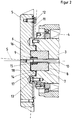
- 2 shows an enlarged illustration of the centering area between the shaft journal 3 and the drum body 5.
- the centering sleeve 8 and the spacer sleeve 9 are shown in an enlarged view.
- the centering sleeve 8 can be seen as the central element.
- the centering sleeve 8 is firmly seated in the shaft journal 3 and is crowned at the end projecting from the shaft journal 3.
- the centering hole 6 in the drum body 5, like the paired outer surface of the centering sleeve 8, is spherical.
- the spherical shape of the centering hole 6 and centering sleeve 8 forms a sliding surface 14 in the contact area.
- This sliding surface 14 is designed as an inner annular surface and chamfer 17 on the outer end face of the centering hole 6 on the drum body 5.
- the sliding surface 14 is designed as an outer ring surface and chamfer 18 towards the end face of the centering sleeve 8 towards its end on the drum side.
- the drum body 5 When the drum body 5 is pivoted with respect to the axis of the shaft journal 3, the drum body 5 can thus carry out a rolling motion on the outer surface of the centering sleeve 8 in the region of the sliding surface 14.
- the radial remains Positioning between drum body 5 and shaft journal 3 is completely preserved, since the pairing of center hole 6 and centering sleeve 8 is free of play.
- the position in the axial direction is constantly secured by the fact that the drum body 5 is secured to an end face 15 of the spacer sleeve 9 by means of the pull rod 10. This forms a quasi-punctiform support for the drum body 5 with respect to the shaft journal 3.
- the end face 15 of the spacer bush 9 has such a small diameter that one can speak of a punctiform support.
- the entire arrangement is very easy to assemble and inexpensive to manufacture.
- the sheet transport drum is preassembled, as is the bearing unit of the drive gear 2.
- Centering sleeve 8, spacer sleeve 9 and coupling plate 11 are fastened or inserted on the shaft journal 3.
- the drum body 5 has been pushed onto the centering sleeve 8 by means of the centering hole 6, the position can be secured by means of the pull rod 10. Thereafter, only the correct connection in the direction of rotation is required by attaching the screw 12 between coupling plate 11 and drum body 5.
Landscapes
- Registering Or Overturning Sheets (AREA)
- Rolls And Other Rotary Bodies (AREA)
- Feeding Of Articles By Means Other Than Belts Or Rollers (AREA)
Abstract
Description
- Die Verbesserung betrifft eine Vorrichtung zur schwenkbaren Lagerung einer Bogentransporttrommel gegenüber einer antriebsseitigen Lagerung. Eine Vorrichtung dieser Art ist aus der DE-OS 4 012 928 bekannt.
- Beim Mehrfarbendruck in Bogenrotationsdruckmaschinen werden Teilbilder zur Erzeugung eines Farbbildes übereinandergedruckt. Dabei treten Fehler in der Lage der verschiedenen Teilbilder zueinander auf. Fehler, die in Transportrichtung des Druckbildes oder in Seitenrichtung quer dazu erkennbar sind, werden auf konventionelle Weise durch Verstellen eines eine Druckplatte eines der Teilbilder tragenden Plattenzylinders behoben. Dieser kann in Umfangsrichtung und in axialer Richtung verstellt werden. Fehler, die sich in Form einer Schräglage zwischen Teilbildern darstellen, sind schwieriger zu beheben. Einerseits wird dazu die Verschiebung der Druckplatte auf dem Plattenzylinder eingesetzt oder nach neuerer Erkenntnis auch die Schrägstellung einer Bogentransporttrommel. Beim Schrägstellen einer Bogentransporttrommel tritt allerdings das Problem auf, daß das Antriebszahnrad der genannten Bogentransporttrommel gegebenenfalls mit dem Trommelkörper schräggestellt wird. Dies ist für die Antriebsverhältnisse unzumutbar und würde zu erhöhtem Verschleiß führen.
- In der DE-OS 4 012 928 ist eine Bogentransporttrommel für Schrägregisterkorrektur bekannt geworden. Sie zeigt auf, daß der Trommelkörper gegen die antriebsseitige Festlagerung verschwenkbar ist. Dazu ist beispielsweise der Trommelkörper mit dem antriebsseitigen Wellenzapfen über eine verformbare Scheibe verbunden. Die Scheibe läßt Bewegungen des Trommelkörpers quer zur Trommelachse zu. Sie überträgt allerdings die Antriebsbewegung vom Antriebszahnrad starr auf den Trommelkörper. Da der Trommelkörper auf seiner anderen Seite in einem Lagerzapfen mit exzentrischer Buchse gelagert ist, kann mittels der exzentrischen Buchse eine Schrägstellung des Trommelkörpers ohne Bewegung des Antriebszahnrades erreicht werden. Die in der DE-OS 4 012 928 gezeigte Vorrichtung weist allerdings den Nachteil auf, daß bei der Verstellung in Schrägrichtung sich immer noch Zwangskräfte auf die Lagerung des Antriebszahnrades entwickeln können. Dies rührt daher, daß die Scheibe, die die alleinige Führung des Trommelkörpers an dem antriebsseitigen Wellenzapfen in radialer, axialer und Umfangsrichtung übernimmt, relativ steif und damit immer noch in gewissem Maße widerstandsfähig gegen Biegung ausgebildet sein muß. Eine vollständige Entlastung der antriebsseitigen Lagerung von Zwangskräften ist damit noch nicht vollständig möglich.
- Ziel der Erfindung ist es daher, eine optimale Entkoppelung der Zwangskräfte aus der Schrägstellung des Trommelkörpers von der Lagerung auf der Antriebsseite vorzunehmen. Gleichzeitig soll eine verbesserte Zentrierung des Trommelkörpers gegenüber der antriebsseitigen Festlagerung ermöglicht werden.
- Aufgabe der Erfindung ist es also an einer Vorrichtung nach dem Oberbegriff des Anspruchs 1 die resultierenden Kräfte aus der Schrägstellung des Trommelkörpers optimal von der antriebsseitigen Lagerung fernzuhalten.
- Die Lösung der Aufgabe gestaltet sich nach dem Kennzeichen des Anspruches 1. Hierbei sind die radialen und malen Verbindungen vorteilhaft voneinander getrennt und insbesondere auch von der Drehübertragung abgekoppelt. Durch die beanspruchte Konzeption der Ankoppelung kann sich keine Veränderung der Lage des Trommelkörpers in axialer Richtung mehr ergeben und weiterhin werden die durch die Schrägstellung bedingten Zwangskräfte auf die antriebsseitige Lagerung nochmals erheblich gegenüber dem schon recht guten Ausgangszustand reduziert.
- Die Vorrichtung wird im folgenden anhand von zeichnerischen Darstellungen in einem Ausführungsbeispieles näher dargestellt. Dabei wird in den Zeichnungen im einzelnen dargestellt, in
- Fig. 1
- die Lagerung des Antriebszahnrades mit Anbindung des Trommelkörpers und
- Fig. 2
- eine detaillierte Darstellung der Zentrierung.
- In Fig. 1 ist die antriebsseitige Lagerung einer Bogentransporttrommel gezeigt. Die Bogentransporttrommel selbst ist nicht dargestellt. In einer Gestellwand 1 ist ein Antriebszahnrad 2 über seinen Wellenzapfen 3 gelagert. Die Lagerung 4 ist in einer Hülse in der Gestellwand 1 befestigt. Mit dem Wellenzapfen 3 ist ein Trommelkörper 5 der Bogentransporttrommel gekoppelt. Dazu ist in dem Trommelkörper 5 eine Zentrierbohrung 6 vorgesehen und in dem Wellenzapfen 3 ist eine Zentrierbohrung 7 vorgesehen. In diesen Zentrierbohrungen 6, 7 ist eine Zentrierhülse 8 eingesetzt. Die Zentrierhülse 8 ist ein hohlzylindrisches Teil, das die Nahtstelle zwischen Trommelkörper 5 und Wellenzapfen 3 übergreift. Weiterhin ist innerhalb der Zentrierhülse 8 eine Vergrößerung der Bohrung vorgesehen, so daß dort eine Abstandsbuchse 9 eingesetzt werden kann. Die Abstandsbuchse 9 überragt in ihrer Länge die Zentrierhülse 8 um ein geringes Maß. Die Verbindung des Trommelkörpers 5 mit dem Wellenzapfen 3 wird mit Hilfe einer Zugstange 10 hergestellt. Sie durchgreift den Wellenzapfen 3 und die Abstandsbuchse 9 und wird im Trommelkörper 5 verschraubt.
- Damit ist zwischen dem Trommelkörper 5 und dem Wellerzapfen 3 sowohl in radialer Richtung über die Zentrierhülse 8 als auch in axialer Richtung über die Kombination von Abstandsbuchse 9 und Zentrierhülse 8 mit der Zugstange 10 eine sichere Führung erreicht.
- Der Trommelkörper 5 ist radial spielfrei an der überstehenden Außenfläche der Zentrierhülse 8 geführt und wird in axialer Richtung spielfrei durch die Zugstange 10 entgegen die Abstandsbuchse 9 gehalten.
- Die Drehübertragung des Antriebsmomentes von dem Anthebszahnrad 2 über da Wellenzapfen 3 auf den Trommelkörper 5 wird von einer Koppelscheibe 11 übernommen. Die Koppelscheibe 11 ist als flacher Ring ausgebildet. Sie ist an ihrem äußeren Umfang mit einer Verschraubung 12 an dem Trommelkörper 5 angekoppelt. An ihrem inneren Umfang ist eine weitere Verschraubung 13 zur Ankoppelung an den Wellenzapfen 3 vorgesehen. Die Verschraubungen 12, 13 stellen sicher, daß in Drehrichtung der Bogentransporttrommel eine spielfreie und paßgenaue Ankoppelung des Antriebszahnrades 2 zum Trommelkörper 5 erfolgt. Außerdem ist mittels der Koppelscheibe 11 im weiten Umfang einer axiale bzw. Schwenkbewegung zwischen Trommelkörper 5 und Wellenzapfen 3 möglich.
- Zur Registerkorrektur wird, wie bereits erwähnt, eine Schrägstellung der Bogentransporttrommel vorgenommen. Die Schrägstellung stellt sich im weiteren als Verlagerung der Achse des Trommelkörpers 5 gegenüber der Achse des Wellenzapfens 3 dar. Sie ist in Fig. 1 mit der strichierten Linie S bezeichnet. Bei der Schrägstellung des Trommelkörpers 5 ist im Bereich der Zentrierung des Trommelkörpers 5 gegenüber dem Wellenzapfen 3 eine Bewegung erforderlich. In Fig. 2 ist eine vergrößerte Darstellung des Zentrierbereiches zwischen Wellenzapfen 3 und Trommelkörper 5 gezeigt. Hier sind insbesondere die Zentrierhülse 8 und die Abstandsbuchse 9 in Vergrößerung dargestellt.
- In Fig. 2 sind weitere Details der Verbindung zwischen dem Wellenzapfen 3 und dem Trommelkörper 5 dargestellt. Wesentlich ist hierbei die Winkelbeweglichkeit zwischen Wellenzapfen 3 und Trommelkörper 5.
- Als zentrales Element ist die Zentrierhülse 8 erkennbar. Die Zentrierhülse 8 sitzt fest in dem Wellenzapfen 3 und ist an dem gegenüber dem Wellenzapfen 3 überstehenden Ende ballig ausgeformt. Auch die Zentrierbohrung 6 im Trommelkörper 5 ist wie die mit ihr gepaarte Außenfläche der Zentrierhülse 8 ballig ausgeformt. Die ballige Ausformung von Zentrierbohrung 6 und Zentrierhülse 8 bildet im Berührungsbereich eine Gleitfläche 14. Diese Gleitfläche 14 ist als innere Ringfläche und Anfasung 17 zur äußeren Stirnseite der Zentrierbohrung 6 am Trommelkörper 5 ausgebildet. Als Gegenfläche ist die Gleitfläche 14 als äußere Ringfläche und Anfasung 18 zur Stirnseite der Zentrierhülse 8 zu ihrem trommelseitigen Ende hin ausgeführt.
- Bei einer Verschwenkung des Trommelkörpers 5 gegenüber der Achse des Wellenzapfens 3 kann somit der Trommelkörper 5 quasi auf der Außenfläche der Zentrierhülse 8 im Bereich der Gleitfläche 14 eine Abwälzbewegung ausführen. Dabei bleibt die radiale Positionierung zwischen Trommelkörper 5 und Wellenzapfen 3 vollkommen erhalten, da die Paarung von Zentrierbohrung 6 und Zentrierhülse 8 spielfrei ist. Die Position in axialer Richtung wird dabei ständig durch die mittels der Zugstange 10 gesicherte Anlage des Trommelkörpers 5 an einer Stirnfläche 15 der Abstandsbuchse 9 gesichert. Diese bildet quasi eine punktförmige Auflage für den Trommelkörper 5 gegenüber dem Wellenzapfen 3. Die Stirnfläche 15 der Abstandsbuchse 9 hat einen so kleinen Durchmesser, daß man von einer punktförmigen Auflage sprechen kann.
- Bei der Verschwenkung des Trommelkörpers 5 gegenüber dem Wellenzapfen 3 treten nun mehr keine Zwangskräfte mehr auf Die Koppelscheibe 11 ist quer zu ihrer Ausdehnungsebene gerade so schwach ausgebildet, daß sie keine Zwangskräfte aufbauen kann. Andererseits ist sie aber in ihrer Ausdehnungsebene so steif, daß sie in Drehrichtung alle Kräfte versetzungsfrei übertragen kann.
Außerdem ist in Fig. 2 erkennbar, daß die Abstandsbuchse 9 mittels eines Führungsringes 16 innerhalb der Zentrierhülse 8 geführt wird. - Die gesamte Anordnung ist sehr montagefreundlich und günstig in der Herstellung. Die Bogentransporttrommel wird ebenso wie die Lagerungseinheit des Antriebszahnrades 2 vormontiert. Dabei sind Zentrierhülse 8, Abstandsbuchse 9 und Koppelscheibe 11 an dem Wellenzapfen 3 befestigt bzw. eingesetzt. Nach dem aufschieben des Trommelkörpers 5 mittels der Zentrierbohrung 6 auf die Zentrierhülse 8 kann die Lage mittels der Zugstange 10 gesichert werden. Danach ist lediglich noch die passgerechte Verbindung in Drehrichtung durch anbringen der Verschraubung 12 zwischen Koppelscheibe 11 und Trommelkörper 5 erforderlich.
-
- 1
- Gestell
- 2
- Antriebszahnrad
- 3
- Wellenzapfen
- 4
- Lagerung
- 5
- Trommelkörper
- 6
- Zentrierbohrung
- 7
- Zentrierbohrung
- 8
- Zentrierhülse
- 9
- Abstandsbuchse
- 10
- Zugstange
- 11
- Koppelscheibe
- 12
- Verschraubung
- 13
- Verschraubung
- 14
- Gleitfläche
- 15
- Stirnfläche
- 16
- Führungsring
- 17
- Anfasung
- 18
- Anfasung
Claims (3)
- Vorrichtung zur schwenkbaren Lagerung einer Bogentransporttrommel gegenüber einer antriebsseitigen Lagerung in einer Bogenrotationsdruckmaschine, mit einem Trommelkörper, einem Wellenzapfen in einer Festlagerung eines Antriebszahnrades und einer schwenkbaren aber radial und tangential steifen Verbindung zwischen dem Wellenzapfen und dem Trommelkörper in Form einer Koppelscheibe,
dadurch gekennzeichnet,
daß die Koppelscheibe (11) jeweils stirnseitig mit dem Trommelkörper (5) und dem Wellenzapfen (3) verbunden ist,
daß ein Zentrierelement (8) zur radial spielfreien, koaxialen Verbindung zwischen Wellenzapfen (3) und Trommelkörper (5) vorgesehen ist, und
daß zentrisch zu Wellenzapfen (3) und Trommelkörper (5) eine vorspannbare Stützeinrichtung (9, 10) zur axial spielfreien Verbindung von Wellenzapfen (3) und Trommelkörper (5) vorgesehen ist. - Vorrichtung nach Anspruch 1,
dadurch gekennzeichnet,
daß das Zentrierelement als Zentrierhülse (8) ausgebildet ist, daß die Zentrierhülse (8) eine äußere Gleitfläche (14) aufweist, die mit einer entsprechenden Gleitfläche (14) in einer Zentrierbohrung (6) des Trommelkörpers (5) spielfrei zusammenwirkt, und daß an der Zentrierhülse (8) eine axiale Stützfläche (15) zur Anlage an dem Trommelkörper (5) vorgesehen ist. - Vorrichtung nach Anspruch 1 oder 2,
dadurch gekennzeichnet,
daß innerhalb der Zentrierhülse (8) eine Abstandsbuchse (9) vorgesehen ist, die aus der Zentrierhülse (8) vorsteht und daß eine Zugstange (10) den Wellenzapfen (3) zentrisch durchgreift und Wellenzapfen (3) und Trommelkörper (5) unter Einspannung der Abstandsbuchse (9) vorspannbar miteinander verbindet.
Applications Claiming Priority (2)
| Application Number | Priority Date | Filing Date | Title |
|---|---|---|---|
| DE29505822U | 1995-04-05 | ||
| DE29505822U DE29505822U1 (de) | 1995-04-05 | 1995-04-05 | Bogentransporttrommel mit Schrägregisterkorrektur |
Publications (3)
| Publication Number | Publication Date |
|---|---|
| EP0736377A2 true EP0736377A2 (de) | 1996-10-09 |
| EP0736377A3 EP0736377A3 (de) | 1997-02-19 |
| EP0736377B1 EP0736377B1 (de) | 1997-10-22 |
Family
ID=8006435
Family Applications (1)
| Application Number | Title | Priority Date | Filing Date |
|---|---|---|---|
| EP96105040A Expired - Lifetime EP0736377B1 (de) | 1995-04-05 | 1996-03-29 | Bogentransporttrommel mit Schrägregisterkorrektur |
Country Status (3)
| Country | Link |
|---|---|
| EP (1) | EP0736377B1 (de) |
| AT (1) | ATE159459T1 (de) |
| DE (2) | DE29505822U1 (de) |
Families Citing this family (3)
| Publication number | Priority date | Publication date | Assignee | Title |
|---|---|---|---|---|
| DE19852361A1 (de) * | 1998-11-13 | 2000-05-25 | Roland Man Druckmasch | Vorrichtung zur Korrektur der Winkelabweichung der einer Druckmaschine zugeführten Bogen |
| DE10119140A1 (de) | 2000-05-17 | 2001-11-22 | Heidelberger Druckmasch Ag | Bedruckstoffbögen verarbeitende Maschine |
| DE10151490B4 (de) * | 2001-10-18 | 2017-04-13 | Heidelberger Druckmaschinen Ag | Diagonalregister für Druckmaschinen, insbesondere Bogenoffsetmaschinen mit Lackierwerk |
Family Cites Families (5)
| Publication number | Priority date | Publication date | Assignee | Title |
|---|---|---|---|---|
| US1445272A (en) * | 1921-06-17 | 1923-02-13 | Edwin R Gill | Universal joint for power transmission |
| DE2402101C3 (de) * | 1974-01-17 | 1978-09-14 | Maschinenfabrik Augsburg-Nuernberg Ag, 8900 Augsburg | Einrichtung zum Verbinden des Fonnzylinders einer Rotations-Druckmaschine mit dessen Antriebswelle |
| US4265099A (en) * | 1979-03-02 | 1981-05-05 | General Electric Company | Flexible coupling |
| DE3913339A1 (de) * | 1989-04-22 | 1990-10-25 | Koenig & Bauer Ag | Seiten- und umfangsregistereinstellvorrichtung fuer eine registertrommel einer bogenrotationsdruckmaschine |
| DE4012928C2 (de) * | 1990-04-24 | 1997-01-09 | Roland Man Druckmasch | Bogentransporttrommel für Schrägregisterkorrektur |
-
1995
- 1995-04-05 DE DE29505822U patent/DE29505822U1/de not_active Expired - Lifetime
-
1996
- 1996-03-29 EP EP96105040A patent/EP0736377B1/de not_active Expired - Lifetime
- 1996-03-29 AT AT96105040T patent/ATE159459T1/de not_active IP Right Cessation
- 1996-03-29 DE DE59600033T patent/DE59600033D1/de not_active Expired - Lifetime
Also Published As
| Publication number | Publication date |
|---|---|
| DE29505822U1 (de) | 1995-06-01 |
| EP0736377B1 (de) | 1997-10-22 |
| DE59600033D1 (de) | 1997-11-27 |
| EP0736377A3 (de) | 1997-02-19 |
| ATE159459T1 (de) | 1997-11-15 |
Similar Documents
| Publication | Publication Date | Title |
|---|---|---|
| EP0248917B1 (de) | Vorrichtung an einer Presse mit Exzenterwelle zum Verstellen des Stösselhubes | |
| DE3103172C2 (de) | Axial verschiebbare Gleichlaufgelenkkupplung | |
| EP0741015B1 (de) | Vorrichtung zum umfänglichen und seitlichen Verstellen des Plattenzylinders | |
| WO2012022310A2 (de) | Vorrichtung zum andrücken einer zahnstange | |
| EP0527405A1 (de) | Dreiringwälzlager für die Zapfen der Zylinder von Druckmaschinen | |
| EP0981443B1 (de) | Antrieb für ein rotierendes bauteil einer rotationsdruckmaschine | |
| EP0864379B1 (de) | Klemmverbindung zwischen einem Spindelkopf und einem Walzenzapfen | |
| DE2711890C2 (de) | ||
| DE2402101C3 (de) | Einrichtung zum Verbinden des Fonnzylinders einer Rotations-Druckmaschine mit dessen Antriebswelle | |
| EP0679596B1 (de) | Leitwalze für Bahnmaterial, insbesondere für Papierherstell und -veredlungsmaschinen | |
| EP0736377B1 (de) | Bogentransporttrommel mit Schrägregisterkorrektur | |
| EP0453789A1 (de) | Bogentransporttrommel, deren Achse an einem Ende unverschiebbar und am anderen Ende translatorisch bewegbar gelagert ist | |
| EP1232062A1 (de) | Lagerung eines zylinders einer rotationsdruckmaschine | |
| EP0713023B1 (de) | Wellenkupplung | |
| DE10014040B4 (de) | Welle zum Synchronisieren einer Stellbewegung | |
| EP1530685B1 (de) | Anschlusselement zur verbindung von gelenkspindeln mit anschlussaggregaten, insbesondere trefferhalterung mit konischer zentrierung | |
| DE3419307A1 (de) | Anordnung zur loesbaren reibschlussverbindung zwischen einer als hohlwelle ausgebildeten getriebeeingangswelle und einer in diese einschiebbaren antriebswelle | |
| EP2848806B9 (de) | Hydrostatische Axialkolbenmaschine in Schrägachsenbauweise mit einem Gleichlaufgelenk zur Mitnahme der Zylindertrommel | |
| DE2825556C2 (de) | Kreuzgelenkkupplung | |
| DE69105204T2 (de) | Lagervorrichtung für das seitenregister. | |
| DE10316261B4 (de) | Kupplungsnabe zum Kuppeln insbesondere einer Gelenkwelle mit einem Wellenzapfen | |
| EP2835531A2 (de) | Hydrostatische Axialkolbenmaschine in Schrägachsenbauweise | |
| DE4205653A1 (de) | Kreuzgelenk | |
| DE10043524A1 (de) | Kraftfahrzeugsitz mit neigungseinstellbarer Rückenlehne | |
| DE10066156B4 (de) | Welle zum Synchronisieren einer Stellbewegung |
Legal Events
| Date | Code | Title | Description |
|---|---|---|---|
| PUAI | Public reference made under article 153(3) epc to a published international application that has entered the european phase |
Free format text: ORIGINAL CODE: 0009012 |
|
| 17P | Request for examination filed |
Effective date: 19960418 |
|
| AK | Designated contracting states |
Kind code of ref document: A2 Designated state(s): AT BE CH DE FR GB IT LI NL SE |
|
| PUAL | Search report despatched |
Free format text: ORIGINAL CODE: 0009013 |
|
| AK | Designated contracting states |
Kind code of ref document: A3 Designated state(s): AT BE CH DE FR GB IT LI NL SE |
|
| GRAG | Despatch of communication of intention to grant |
Free format text: ORIGINAL CODE: EPIDOS AGRA |
|
| GRAH | Despatch of communication of intention to grant a patent |
Free format text: ORIGINAL CODE: EPIDOS IGRA |
|
| 17Q | First examination report despatched |
Effective date: 19970326 |
|
| GRAH | Despatch of communication of intention to grant a patent |
Free format text: ORIGINAL CODE: EPIDOS IGRA |
|
| GRAA | (expected) grant |
Free format text: ORIGINAL CODE: 0009210 |
|
| AK | Designated contracting states |
Kind code of ref document: B1 Designated state(s): AT BE CH DE FR GB IT LI NL SE |
|
| REF | Corresponds to: |
Ref document number: 159459 Country of ref document: AT Date of ref document: 19971115 Kind code of ref document: T |
|
| REG | Reference to a national code |
Ref country code: CH Ref legal event code: NV Representative=s name: E. BLUM & CO. PATENTANWAELTE Ref country code: CH Ref legal event code: EP |
|
| GBT | Gb: translation of ep patent filed (gb section 77(6)(a)/1977) |
Effective date: 19971024 |
|
| ET | Fr: translation filed | ||
| REF | Corresponds to: |
Ref document number: 59600033 Country of ref document: DE Date of ref document: 19971127 |
|
| PLBE | No opposition filed within time limit |
Free format text: ORIGINAL CODE: 0009261 |
|
| STAA | Information on the status of an ep patent application or granted ep patent |
Free format text: STATUS: NO OPPOSITION FILED WITHIN TIME LIMIT |
|
| 26N | No opposition filed | ||
| REG | Reference to a national code |
Ref country code: GB Ref legal event code: IF02 |
|
| PGFP | Annual fee paid to national office [announced via postgrant information from national office to epo] |
Ref country code: CH Payment date: 20030218 Year of fee payment: 8 |
|
| PGFP | Annual fee paid to national office [announced via postgrant information from national office to epo] |
Ref country code: GB Payment date: 20030226 Year of fee payment: 8 |
|
| PGFP | Annual fee paid to national office [announced via postgrant information from national office to epo] |
Ref country code: NL Payment date: 20030228 Year of fee payment: 8 |
|
| PGFP | Annual fee paid to national office [announced via postgrant information from national office to epo] |
Ref country code: SE Payment date: 20030304 Year of fee payment: 8 Ref country code: AT Payment date: 20030304 Year of fee payment: 8 |
|
| PGFP | Annual fee paid to national office [announced via postgrant information from national office to epo] |
Ref country code: FR Payment date: 20030314 Year of fee payment: 8 |
|
| PGFP | Annual fee paid to national office [announced via postgrant information from national office to epo] |
Ref country code: BE Payment date: 20030320 Year of fee payment: 8 |
|
| PG25 | Lapsed in a contracting state [announced via postgrant information from national office to epo] |
Ref country code: GB Free format text: LAPSE BECAUSE OF NON-PAYMENT OF DUE FEES Effective date: 20040329 Ref country code: AT Free format text: LAPSE BECAUSE OF NON-PAYMENT OF DUE FEES Effective date: 20040329 |
|
| PG25 | Lapsed in a contracting state [announced via postgrant information from national office to epo] |
Ref country code: SE Free format text: LAPSE BECAUSE OF NON-PAYMENT OF DUE FEES Effective date: 20040330 |
|
| PG25 | Lapsed in a contracting state [announced via postgrant information from national office to epo] |
Ref country code: LI Free format text: LAPSE BECAUSE OF NON-PAYMENT OF DUE FEES Effective date: 20040331 Ref country code: CH Free format text: LAPSE BECAUSE OF NON-PAYMENT OF DUE FEES Effective date: 20040331 Ref country code: BE Free format text: LAPSE BECAUSE OF NON-PAYMENT OF DUE FEES Effective date: 20040331 |
|
| BERE | Be: lapsed |
Owner name: *MAN ROLAND DRUCKMASCHINEN A.G. Effective date: 20040331 |
|
| PG25 | Lapsed in a contracting state [announced via postgrant information from national office to epo] |
Ref country code: NL Free format text: LAPSE BECAUSE OF NON-PAYMENT OF DUE FEES Effective date: 20041001 |
|
| EUG | Se: european patent has lapsed | ||
| REG | Reference to a national code |
Ref country code: CH Ref legal event code: PL |
|
| GBPC | Gb: european patent ceased through non-payment of renewal fee |
Effective date: 20040329 |
|
| PG25 | Lapsed in a contracting state [announced via postgrant information from national office to epo] |
Ref country code: FR Free format text: LAPSE BECAUSE OF NON-PAYMENT OF DUE FEES Effective date: 20041130 |
|
| NLV4 | Nl: lapsed or anulled due to non-payment of the annual fee |
Effective date: 20041001 |
|
| REG | Reference to a national code |
Ref country code: FR Ref legal event code: ST |
|
| PG25 | Lapsed in a contracting state [announced via postgrant information from national office to epo] |
Ref country code: IT Free format text: LAPSE BECAUSE OF NON-PAYMENT OF DUE FEES Effective date: 20050329 |
|
| PGFP | Annual fee paid to national office [announced via postgrant information from national office to epo] |
Ref country code: DE Payment date: 20100324 Year of fee payment: 15 |
|
| PG25 | Lapsed in a contracting state [announced via postgrant information from national office to epo] |
Ref country code: DE Free format text: LAPSE BECAUSE OF NON-PAYMENT OF DUE FEES Effective date: 20111001 |
|
| REG | Reference to a national code |
Ref country code: DE Ref legal event code: R119 Ref document number: 59600033 Country of ref document: DE Effective date: 20111001 |