EP0736387A1 - Vorrichtung zum Wiederherstellen der Wirkung der Austrittsdüsen von Tintenstrahldruckgeräten - Google Patents
Vorrichtung zum Wiederherstellen der Wirkung der Austrittsdüsen von Tintenstrahldruckgeräten Download PDFInfo
- Publication number
- EP0736387A1 EP0736387A1 EP95500043A EP95500043A EP0736387A1 EP 0736387 A1 EP0736387 A1 EP 0736387A1 EP 95500043 A EP95500043 A EP 95500043A EP 95500043 A EP95500043 A EP 95500043A EP 0736387 A1 EP0736387 A1 EP 0736387A1
- Authority
- EP
- European Patent Office
- Prior art keywords
- vacuum
- cycle
- ink
- nozzles
- nozzle
- Prior art date
- Legal status (The legal status is an assumption and is not a legal conclusion. Google has not performed a legal analysis and makes no representation as to the accuracy of the status listed.)
- Granted
Links
Images




Classifications
-
- B—PERFORMING OPERATIONS; TRANSPORTING
- B41—PRINTING; LINING MACHINES; TYPEWRITERS; STAMPS
- B41J—TYPEWRITERS; SELECTIVE PRINTING MECHANISMS, i.e. MECHANISMS PRINTING OTHERWISE THAN FROM A FORME; CORRECTION OF TYPOGRAPHICAL ERRORS
- B41J2/00—Typewriters or selective printing mechanisms characterised by the printing or marking process for which they are designed
- B41J2/005—Typewriters or selective printing mechanisms characterised by the printing or marking process for which they are designed characterised by bringing liquid or particles selectively into contact with a printing material
- B41J2/01—Ink jet
- B41J2/135—Nozzles
- B41J2/165—Prevention or detection of nozzle clogging, e.g. cleaning, capping or moistening for nozzles
- B41J2/16517—Cleaning of print head nozzles
- B41J2/1652—Cleaning of print head nozzles by driving a fluid through the nozzles to the outside thereof, e.g. by applying pressure to the inside or vacuum at the outside of the print head
- B41J2/16523—Waste ink transport from caps or spittoons, e.g. by suction
-
- B—PERFORMING OPERATIONS; TRANSPORTING
- B41—PRINTING; LINING MACHINES; TYPEWRITERS; STAMPS
- B41J—TYPEWRITERS; SELECTIVE PRINTING MECHANISMS, i.e. MECHANISMS PRINTING OTHERWISE THAN FROM A FORME; CORRECTION OF TYPOGRAPHICAL ERRORS
- B41J2/00—Typewriters or selective printing mechanisms characterised by the printing or marking process for which they are designed
- B41J2/005—Typewriters or selective printing mechanisms characterised by the printing or marking process for which they are designed characterised by bringing liquid or particles selectively into contact with a printing material
- B41J2/01—Ink jet
- B41J2/135—Nozzles
- B41J2/165—Prevention or detection of nozzle clogging, e.g. cleaning, capping or moistening for nozzles
- B41J2/16505—Caps, spittoons or covers for cleaning or preventing drying out
- B41J2/16508—Caps, spittoons or covers for cleaning or preventing drying out connected with the printer frame
Definitions
- the present invention relates to a new device for recovering the operation of the nozzles of devices for ink-jet injection printing.
- Ink-jet injection devices have nozzles through which droplets of ink are projected at high speed forming the so-called “ink jets" which are intended to fall on the printing substrate, normally paper, in order to effect the expected trace.
- One of the problems of the said ink-jet printing devices consists of loss of functionality in the injection nozzles, particularly owing to blockage thereof which usually takes place as a result of partial drying of the residual ink in the nozzles.
- many known ink-jet printing devices have systems for hermetically sealing the nozzles once they have stopped working, which decreases the chance of evaporation of the ink and the formation of sediments which give rise to blockage.
- blockages of some nozzles appear, preventing correct operation thereof. This phenomenon may occur mainly in multi-coloured ink-jet printing devices and, in particular, for the colours which are used less frequently.
- the main disadvantage of the currently-known devices for recovering nozzles consists of their mechanical complexity, their weight and their high cost which constitutes a disadvantage in the development of cheap devices for multi-coloured ink-jet printing.
- the object of the present invention is to provide a device which has appreciable features of novelty and inventive step, enabling the operation of the nozzles for the injection of ink to be recovered effectively and at the same time by simple and cheap means.
- the present invention comprises a wholly mechanical device for producing a pulse of vacuum or sub-pressure which can be applied to any of the nozzles of the ink-jet printing device, comprising essentially mechanically-operated, spring-returned means for generating a vacuum and a set of individual pipes for connecting the said vacuum generator to the outlets of the individual nozzles of the printing device, having means for keeping the various communication pipes closed for normal operation and permitting optional opening thereof at the moment when it is necessary to recover the operation of one of the nozzles.
- the mechanical device for generating a vacuum comprises essentially, a resilient bellows element which tends to remain in a slackened position owing to the action of a return spring and which can be compressed by the operation of a manual control which, for greater convenience, is provided with a simple push-button and an intermediate rocker arm which acts on the bellows and compresses it.
- the automatic release of the compression of the bellows will cause rapid expansion of the spring and therefore a suction effect in the pipe connected to the nozzle to be restored.
- the various pipes can preferably be closed by a key system with individual mechanisms for gripping and closing the various pipes and for interlocking the various controls in its normal position which corresponds to the closure of the flexible pipes.
- the device is so generally arranged that the level of underpressure transmitted to the pen is independent of the manual handling of the device by the user, given the fact that the rapid expansion of the spring and the stroke of the member which creates the underpressure do not directly receive the action from the user who activates the pusher.
- the present invention also extends to the method of recovering the operation of the nozzles of an ink-jet printing device, which comprises:
- Figure 1 is a cross-section showing schematically the subject of the present invention, as a whole.
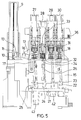
- FIGs 2, 3, 4, 5 and 6 are respective cross-sections taken in the section planes indicated in Figure 1, showing details of the mechanisms which form parts of the present invention.
- Figure 7 is a longitudinal cross-section of the push-button device for operating the manual vacuum pump.
- Figure 8 is an elevational view corresponding to the push-button of Figure 7.
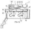
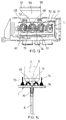
- Figures 9, 10, 11, 12, 13 and 14 are respective cross-section details in the section planes indicated, which show the support for the closure of the nozzles in the rest position as well as the manner in which it is set and released.
- FIGS 1, 2 and 3 show the main mechanisms of the device of the present invention.
- the said figures show the movable unit 1 which is intended to close the various nozzles of the ink-jet printing device which comprises ink cartridges, indicated 2 and shown in broken outline, for each of the colours required.
- the movable closure device 1 blocks the outlet 3 of the cartridge and therefore the corresponding nozzle, by means of its base plate 76, in the rest position of the head of the ink-jet printing device, generally indicated 4, the guide for the longitudinal displacement of which is indicated 5.
- the detailed construction of the movable closure unit 1 will be described below.
- Each of the outlets 3 is connected, by means of a bout or nipple formed in the plate 76, to a flexible pipe 6 which communicates with the manually-operated vacuum generating unit 7 in a manner such that each cycle for the recovery of a nozzle will involve the operation of the vacuum unit 7 and its communication with the obstructed nozzle through the corresponding duct 6.
- the device will have as many pipes 6 as the ink-jet printing device has injection nozzles, which is normally four for colour printing.
- the vacuum generating unit 7 will comprise a bellows device with a return spring 8 and an operating push-button 9 which can preferably be disposed vertically to facilitate the exertion of the compression effort in the most ergonomic position for the arm.
- the said push-button is acted on by a return spring 10 ( Figure 7) and has a projecting stub 11 which is intended to bear on the intermediate rocker arm 12 which has an arm 13 and bears on a thrust element 14 incorporated in the end of the bellows 7.
- the said rocker arm 12 is pivotable about a transverse axis 77 in the body 15 supporting the vacuum unit and also has a resilient abuttment 16 which, in combination with a fixed abuttment 17 of the support 18, actuates the devices for gripping the various pipes.
- the recovery effect is brought about automatically when, during its downstroke, the push-button 9 reaches a point at which the rocker arm 12 is released from the actuating stub 11, causing the rocker arm to rise again and the bellows 7 to return to an extended position in which a vacuum effect will be exerted in the internal chamber thereof and in the pipe for the recovery of a nozzle, through the distributor 19.
- the underpressure obtained by means of the device does not depend on the action exerted by the user on the push button -9- given the fact that the driving action on the bellows -7- takes place by the action of the spring -8- and the compression stroke is determined by the rocker arm -12- independently of the manual action exerted by the user.
- connection pipes between the suction-cycle generating unit and the nozzle outlets 3 are constituted by two pipe portions 6 and 26, of which one portion 26 is connected between the end distributor 19 of the vacuum-cycle generator and a fixed intermediate distributor body 21 which has as many individual chambers 22, 23, 24 and 25 as there are flexible pipes, the second pipe portion 6 being connected at one end to a corresponding outlet of one of the said individual chambers and at the other end being connected to the movable plate 76 carrying the seals for closing the outlets of the injection nozzles.
- the intermediate distributor body 21 has, as indicated, a series of individual chambers 22 to 25 in which the ink which will be discharged from the corresponding nozzle under the action of the vacuum at the outlet 3 of each of the cartridges 2 can be deposited.
- the present invention provides for a key system having individual keys for gripping the various pipes.
- the said key system is shown, in particular, in Figures 3, 5 and 6 in which can be noted the various keys 27, 28, 29 and 30, the bodies of which have large lower windows, for example, the window indicated 31 for the key 28, the lower edge 32 of which will grip the corresponding pipe which extends through the said window 31 and which is not shown for greater clarity, trapping it against the upper edge 33 of the fixed body 18 carrying the said key.
- Lower return springs such as the spring 34 for the key 28, act on each key and restore the position of the key once it is released, as will be explained below.
- the present device comprises a transversely movable slider 35 which receives the returning action of its own spring 36 and which, for each of the keys, has a projection 37 the upper edge 38 of which is inclined downwardly and which defines, by means of a chamfer 39, a lower flat region 40.
- a projection 41 of the key 28 is disposed in a position perpendicular to the said projection 37 in a manner such that, when the key is displaced vertically, the said projection pushes the transverse slider 35, acting on the inclined plane 38 until, upon passing over the projection 37, the slider 35 will return to the original position, retaining the projection 41 beneath the flat region 40, this position being shown in Figure 6.
- the corresponding pipe which extends through the window 31 is not gripped, that is, it is subject to the effect of the vacuum which will be produced by the expansion of the bellows element after the compression thereof.
- the ink which comes out of the said nozzle will be deposited in a tank 42 in the bottom of the corresponding chamber of the body 21.
- the said tanks will have different dimensions, according to the maximum or peak underpressure which is desired for the different pens being variable, specially taking into colour pens and black pens.
- one of the nozzles may have a tank 43 with much larger dimensions than the others.
- Each chamber of the body 21 which includes the tank 42 and the corresponding projection of those indicated 22 to 25 will also have a small opening, indicated 44, by means of which, after the recovery cycle of the vacuum generating unit, it can return to atmospheric pressure after a certain time as atmospheric air is drawn through the said opening 44.
- the dimensions of said venting openings will be used for the adjustment of the descending part of the underpressure curve created in the corresponding chamber, which will vary according to the entrance of ambient air.
- the vertical push-button 9 has a laterally expanded portion 45 with an inverted U-shaped slot 46 and projecting teeth in its central region 47 in which is inserted an end tooth 48 of a resilient arm 49 fixed to the base 50 of the fixed body carrying the vacuum generating unit.
- the assembly 4 which forms part of the movable carriage, carries various housings such as those indicated 51, 52, 53 and 54, for the various ink cartridges, which will supply the corresponding injection nozzles, the said body being coupled to the unit 1 which carries the means for closing the outlets of the nozzles on one side by means of a lateral fin 55 carrying straight lateral flanges 56 and 57 which are coupled with respective straight housings 58 and 59 of a lateral projecting rib 60 which is present on the body 4 and can guide the latter during entry and exit relative to the unit 1 and to the lateral fin 55.
- the assembly 4 fits onto lateral projections 61, Figure 1, which form part of the unit 1 carrying the means for closing the nozzle outlets.
- the said projections 61 can also be seen in Figure 10 in which it is also possible to see the lower springs 62 and 63 which lift the unit 1 which, laterally, has respective pairs of inclined profiles 64 and 65 which, in combination with downwardly-projecting abuttments which form respective pairs of projections, one of which 66 and 67 is shown in Figure 12, forming part of the fixed body on which the unit 1 is guided, and cooperating with the springs 62 and 63 to convert the longitudinal displacement of the carriage which entrains the body 4 carrying the cartridges 2 into an upward movement of the unit 1 when the carriage reaches the home or rest position, in order to bring about the closure of the nozzles, and into a downward movement of the said unit 1 when the carriage departs again towards the working positions.
- the plate 1 In order close the nozzles, the plate 1 carries a series of suitable seals, indicated 68, 69, 70 and 71 in Figure 13, the number of seals being equal to the number of nozzles to be controlled, the seals having complementary profiles for fitting the outlets of the cartridges 2 carrying the nozzles as indicated in broken outline in Figure 1, with respective surrounding sealing lips as indicated 72 in Figure 14. Intermediate walls, indicated 73 and 74, between each of the successive closures, are made, like the seals and the lips 72, from synthetic rubber to permit easy deformation thereof when the lateral displacements of the carriage take place.
- the unit 1 has lower fixed bouts or nipples 75 in which the lower flexible pipes indicated 6 in Figure 1 are coupled.
Landscapes
- Engineering & Computer Science (AREA)
- Environmental & Geological Engineering (AREA)
- Ink Jet (AREA)
Priority Applications (3)
| Application Number | Priority Date | Filing Date | Title |
|---|---|---|---|
| EP95500043A EP0736387B1 (de) | 1995-04-05 | 1995-04-05 | Vorrichtung zum Wiederherstellen der Wirkung der Austrittsdüsen von Tintenstrahldruckgeräten |
| ES95500043T ES2126861T3 (es) | 1995-04-05 | 1995-04-05 | Dispositivo para la recuperacion funcional de las toberas de inyeccion de aparatos de impresion por chorros de tinta. |
| DE69507011T DE69507011T2 (de) | 1995-04-05 | 1995-04-05 | Vorrichtung zum Wiederherstellen der Wirkung der Austrittsdüsen von Tintenstrahldruckgeräten |
Applications Claiming Priority (1)
| Application Number | Priority Date | Filing Date | Title |
|---|---|---|---|
| EP95500043A EP0736387B1 (de) | 1995-04-05 | 1995-04-05 | Vorrichtung zum Wiederherstellen der Wirkung der Austrittsdüsen von Tintenstrahldruckgeräten |
Publications (2)
| Publication Number | Publication Date |
|---|---|
| EP0736387A1 true EP0736387A1 (de) | 1996-10-09 |
| EP0736387B1 EP0736387B1 (de) | 1998-12-30 |
Family
ID=8221649
Family Applications (1)
| Application Number | Title | Priority Date | Filing Date |
|---|---|---|---|
| EP95500043A Expired - Lifetime EP0736387B1 (de) | 1995-04-05 | 1995-04-05 | Vorrichtung zum Wiederherstellen der Wirkung der Austrittsdüsen von Tintenstrahldruckgeräten |
Country Status (3)
| Country | Link |
|---|---|
| EP (1) | EP0736387B1 (de) |
| DE (1) | DE69507011T2 (de) |
| ES (1) | ES2126861T3 (de) |
Cited By (3)
| Publication number | Priority date | Publication date | Assignee | Title |
|---|---|---|---|---|
| EP0844093A3 (de) * | 1996-11-20 | 1998-08-12 | Nec Corporation | Tintenstrahldrucker mit Schaltventil zwischen Druckkopfkappen und Pumpe |
| US6116719A (en) * | 1997-03-04 | 2000-09-12 | Hewlett-Packard Company | Removable printhead servicing module with remote primer vacuum source |
| WO2019143361A1 (en) * | 2018-01-19 | 2019-07-25 | Hewlett-Packard Development Company, L.P. | Printhead priming and venting |
Citations (4)
| Publication number | Priority date | Publication date | Assignee | Title |
|---|---|---|---|---|
| DE3333626A1 (de) * | 1983-09-17 | 1985-04-18 | Olympia Werke Ag, 2940 Wilhelmshaven | Vorrichtung zum entfernen von schmutz- oder luftteilchen aus einem tintendruckkopf eines schreibwerkes |
| EP0597675A2 (de) * | 1992-11-12 | 1994-05-18 | Xerox Corporation | Ventil für Tintenstrahldruckerwartungssystem |
| EP0622200A1 (de) * | 1993-04-30 | 1994-11-02 | Hewlett-Packard Company | On-line/off-line Inbetriebstellungsvorrichtung für Farbstrahlkassette |
| EP0622201A2 (de) * | 1993-04-30 | 1994-11-02 | Hewlett-Packard Company | Inbetriebstellungsgerät für einen Tintenstrahldrucker |
-
1995
- 1995-04-05 ES ES95500043T patent/ES2126861T3/es not_active Expired - Lifetime
- 1995-04-05 EP EP95500043A patent/EP0736387B1/de not_active Expired - Lifetime
- 1995-04-05 DE DE69507011T patent/DE69507011T2/de not_active Expired - Lifetime
Patent Citations (4)
| Publication number | Priority date | Publication date | Assignee | Title |
|---|---|---|---|---|
| DE3333626A1 (de) * | 1983-09-17 | 1985-04-18 | Olympia Werke Ag, 2940 Wilhelmshaven | Vorrichtung zum entfernen von schmutz- oder luftteilchen aus einem tintendruckkopf eines schreibwerkes |
| EP0597675A2 (de) * | 1992-11-12 | 1994-05-18 | Xerox Corporation | Ventil für Tintenstrahldruckerwartungssystem |
| EP0622200A1 (de) * | 1993-04-30 | 1994-11-02 | Hewlett-Packard Company | On-line/off-line Inbetriebstellungsvorrichtung für Farbstrahlkassette |
| EP0622201A2 (de) * | 1993-04-30 | 1994-11-02 | Hewlett-Packard Company | Inbetriebstellungsgerät für einen Tintenstrahldrucker |
Cited By (4)
| Publication number | Priority date | Publication date | Assignee | Title |
|---|---|---|---|---|
| EP0844093A3 (de) * | 1996-11-20 | 1998-08-12 | Nec Corporation | Tintenstrahldrucker mit Schaltventil zwischen Druckkopfkappen und Pumpe |
| US6050670A (en) * | 1996-11-20 | 2000-04-18 | Nec Corporation | Ink-jet printer with switch valve between caps for printheads and pump |
| US6116719A (en) * | 1997-03-04 | 2000-09-12 | Hewlett-Packard Company | Removable printhead servicing module with remote primer vacuum source |
| WO2019143361A1 (en) * | 2018-01-19 | 2019-07-25 | Hewlett-Packard Development Company, L.P. | Printhead priming and venting |
Also Published As
| Publication number | Publication date |
|---|---|
| ES2126861T3 (es) | 1999-04-01 |
| DE69507011D1 (de) | 1999-02-11 |
| DE69507011T2 (de) | 1999-07-15 |
| EP0736387B1 (de) | 1998-12-30 |
Similar Documents
| Publication | Publication Date | Title |
|---|---|---|
| US7543923B2 (en) | Liquid supply system | |
| US5448271A (en) | Recovery method for ink jet recording head | |
| US5614929A (en) | Manual pen selection for clearing nozzles without removal from pen carriage | |
| US5086305A (en) | Liquid injection recording apparatus and suction recovery device using capping means integrally provided with a plurality of caps | |
| CN100423944C (zh) | 喷墨打印机 | |
| US4492969A (en) | Capping device for a multi-ink jet head | |
| EP0903235A3 (de) | Tintenstrahldrucker mit Vorrichtung zum Durchspülen der Düsen | |
| JPH0740541A (ja) | インクジェット・プリンタのためのプライミング・キャップとプライミング・システム | |
| EP0622200B1 (de) | On-line/off-line Inbetriebstellungsvorrichtung für Farbstrahlkassette | |
| UA26129A (uk) | Пристрій для газуваhhя рідиh, що містяться в пляшках | |
| WO1994013488A1 (fr) | Poste de maintenance et methode d'exploitation de ce poste | |
| JP2022031040A (ja) | 多方式操作可能なアルデヒド除去装置 | |
| EP0736387A1 (de) | Vorrichtung zum Wiederherstellen der Wirkung der Austrittsdüsen von Tintenstrahldruckgeräten | |
| US6513904B1 (en) | Method for servicing an inkjet printhead | |
| US5209379A (en) | Method of assembling a pressurized dispenser and a pressurized dispenser for carrying out said method | |
| AU742152B2 (en) | Device for pneumatic actuation of a cistern | |
| US7814941B2 (en) | Fluid transfer apparatus | |
| EP0764536B1 (de) | Selbstauswählbare Tintenstrahlinbetriebstellungsvorrichtung | |
| CN218091122U (zh) | 一种直动泄压的气动装置、一种气控排水阀及一种水箱 | |
| JP3686730B2 (ja) | インクジェットプリンタの吸引回復装置 | |
| JPS61188156A (ja) | インクジエツトプリンタのキヤツプ装置 | |
| JPS596955A (ja) | エアレス塗装用ダイアフラムポンプ | |
| JPH0117860B2 (de) | ||
| US4646776A (en) | Three-way valve | |
| KR100440968B1 (ko) | 잉크젯 프린터용 잉크 카트리지 |
Legal Events
| Date | Code | Title | Description |
|---|---|---|---|
| PUAI | Public reference made under article 153(3) epc to a published international application that has entered the european phase |
Free format text: ORIGINAL CODE: 0009012 |
|
| 17P | Request for examination filed |
Effective date: 19951108 |
|
| AK | Designated contracting states |
Kind code of ref document: A1 Designated state(s): DE ES FR GB IT |
|
| 17Q | First examination report despatched |
Effective date: 19961126 |
|
| GRAG | Despatch of communication of intention to grant |
Free format text: ORIGINAL CODE: EPIDOS AGRA |
|
| GRAG | Despatch of communication of intention to grant |
Free format text: ORIGINAL CODE: EPIDOS AGRA |
|
| GRAH | Despatch of communication of intention to grant a patent |
Free format text: ORIGINAL CODE: EPIDOS IGRA |
|
| GRAH | Despatch of communication of intention to grant a patent |
Free format text: ORIGINAL CODE: EPIDOS IGRA |
|
| GRAA | (expected) grant |
Free format text: ORIGINAL CODE: 0009210 |
|
| AK | Designated contracting states |
Kind code of ref document: B1 Designated state(s): DE ES FR GB IT |
|
| PG25 | Lapsed in a contracting state [announced via postgrant information from national office to epo] |
Ref country code: IT Free format text: LAPSE BECAUSE OF FAILURE TO SUBMIT A TRANSLATION OF THE DESCRIPTION OR TO PAY THE FEE WITHIN THE PRESCRIBED TIME-LIMIT;WARNING: LAPSES OF ITALIAN PATENTS WITH EFFECTIVE DATE BEFORE 2007 MAY HAVE OCCURRED AT ANY TIME BEFORE 2007. THE CORRECT EFFECTIVE DATE MAY BE DIFFERENT FROM THE ONE RECORDED. Effective date: 19981230 Ref country code: FR Free format text: LAPSE BECAUSE OF FAILURE TO SUBMIT A TRANSLATION OF THE DESCRIPTION OR TO PAY THE FEE WITHIN THE PRESCRIBED TIME-LIMIT Effective date: 19981230 |
|
| REF | Corresponds to: |
Ref document number: 69507011 Country of ref document: DE Date of ref document: 19990211 |
|
| REG | Reference to a national code |
Ref country code: ES Ref legal event code: FG2A Ref document number: 2126861 Country of ref document: ES Kind code of ref document: T3 |
|
| EN | Fr: translation not filed | ||
| PLBE | No opposition filed within time limit |
Free format text: ORIGINAL CODE: 0009261 |
|
| STAA | Information on the status of an ep patent application or granted ep patent |
Free format text: STATUS: NO OPPOSITION FILED WITHIN TIME LIMIT |
|
| 26N | No opposition filed | ||
| REG | Reference to a national code |
Ref country code: GB Ref legal event code: 732E |
|
| REG | Reference to a national code |
Ref country code: GB Ref legal event code: IF02 |
|
| REG | Reference to a national code |
Ref country code: GB Ref legal event code: 732E Free format text: REGISTERED BETWEEN 20120329 AND 20120404 |
|
| REG | Reference to a national code |
Ref country code: ES Ref legal event code: PC2A Owner name: HEWLETT-PACKARD DEVELOPMENT COMPANY, L.P. Effective date: 20120911 |
|
| PGFP | Annual fee paid to national office [announced via postgrant information from national office to epo] |
Ref country code: ES Payment date: 20120426 Year of fee payment: 18 |
|
| PGFP | Annual fee paid to national office [announced via postgrant information from national office to epo] |
Ref country code: GB Payment date: 20130326 Year of fee payment: 19 |
|
| PGFP | Annual fee paid to national office [announced via postgrant information from national office to epo] |
Ref country code: DE Payment date: 20130322 Year of fee payment: 19 |
|
| REG | Reference to a national code |
Ref country code: DE Ref legal event code: R119 Ref document number: 69507011 Country of ref document: DE |
|
| GBPC | Gb: european patent ceased through non-payment of renewal fee |
Effective date: 20140405 |
|
| REG | Reference to a national code |
Ref country code: DE Ref legal event code: R119 Ref document number: 69507011 Country of ref document: DE Effective date: 20141101 |
|
| PG25 | Lapsed in a contracting state [announced via postgrant information from national office to epo] |
Ref country code: GB Free format text: LAPSE BECAUSE OF NON-PAYMENT OF DUE FEES Effective date: 20140405 Ref country code: DE Free format text: LAPSE BECAUSE OF NON-PAYMENT OF DUE FEES Effective date: 20141101 |
|
| REG | Reference to a national code |
Ref country code: ES Ref legal event code: FD2A Effective date: 20150526 |
|
| PG25 | Lapsed in a contracting state [announced via postgrant information from national office to epo] |
Ref country code: ES Free format text: LAPSE BECAUSE OF NON-PAYMENT OF DUE FEES Effective date: 20140406 |