EP0736465A1 - Dispositif de soulèvement/basculement ou de basculement pour le vidage de poubelles - Google Patents
Dispositif de soulèvement/basculement ou de basculement pour le vidage de poubelles Download PDFInfo
- Publication number
- EP0736465A1 EP0736465A1 EP96105152A EP96105152A EP0736465A1 EP 0736465 A1 EP0736465 A1 EP 0736465A1 EP 96105152 A EP96105152 A EP 96105152A EP 96105152 A EP96105152 A EP 96105152A EP 0736465 A1 EP0736465 A1 EP 0736465A1
- Authority
- EP
- European Patent Office
- Prior art keywords
- gripper
- container
- receiving
- receiving device
- tipping
- Prior art date
- Legal status (The legal status is an assumption and is not a legal conclusion. Google has not performed a legal analysis and makes no representation as to the accuracy of the status listed.)
- Granted
Links
Images


Classifications
-
- B—PERFORMING OPERATIONS; TRANSPORTING
- B65—CONVEYING; PACKING; STORING; HANDLING THIN OR FILAMENTARY MATERIAL
- B65F—GATHERING OR REMOVAL OF DOMESTIC OR LIKE REFUSE
- B65F3/00—Vehicles particularly adapted for collecting refuse
- B65F3/02—Vehicles particularly adapted for collecting refuse with means for discharging refuse receptacles thereinto
- B65F3/04—Linkages, pivoted arms, or pivoted carriers for raising and subsequently tipping receptacles
-
- B—PERFORMING OPERATIONS; TRANSPORTING
- B65—CONVEYING; PACKING; STORING; HANDLING THIN OR FILAMENTARY MATERIAL
- B65F—GATHERING OR REMOVAL OF DOMESTIC OR LIKE REFUSE
- B65F3/00—Vehicles particularly adapted for collecting refuse
- B65F3/02—Vehicles particularly adapted for collecting refuse with means for discharging refuse receptacles thereinto
- B65F2003/0223—Vehicles particularly adapted for collecting refuse with means for discharging refuse receptacles thereinto the discharging means comprising elements for holding the receptacle
- B65F2003/024—Means for locking the rim
-
- B—PERFORMING OPERATIONS; TRANSPORTING
- B65—CONVEYING; PACKING; STORING; HANDLING THIN OR FILAMENTARY MATERIAL
- B65F—GATHERING OR REMOVAL OF DOMESTIC OR LIKE REFUSE
- B65F3/00—Vehicles particularly adapted for collecting refuse
- B65F3/02—Vehicles particularly adapted for collecting refuse with means for discharging refuse receptacles thereinto
- B65F2003/0263—Constructional features relating to discharging means
- B65F2003/0276—Constructional features relating to discharging means capable of moving towards or away from the vehicle
-
- B—PERFORMING OPERATIONS; TRANSPORTING
- B65—CONVEYING; PACKING; STORING; HANDLING THIN OR FILAMENTARY MATERIAL
- B65F—GATHERING OR REMOVAL OF DOMESTIC OR LIKE REFUSE
- B65F3/00—Vehicles particularly adapted for collecting refuse
- B65F3/02—Vehicles particularly adapted for collecting refuse with means for discharging refuse receptacles thereinto
- B65F2003/0293—Means mounted on the vehicle for supporting the refuse receptacle in the tipping position
- B65F2003/0296—Means mounted on the vehicle for supporting the refuse receptacle in the tipping position the supporting means mounted on the discharging means
Definitions
- the invention relates to a lifting and tipping device for emptying containers into a collecting container of a garbage truck with a boom arranged on the garbage truck, at the free end of which a receiving frame provided with a receiving device for receiving the container is arranged.
- the emptying devices can be attached to the rear of the garbage truck or to its side wall.
- the problem-free detection of the container requires that the container is aligned largely parallel to the vehicle.
- a pick-up device In order to be able to reliably detect containers that are not exactly aligned, a pick-up device has been created in accordance with EP 0 173 180, which enables oscillation, rotation, inclination and a lateral movement relative to the lifting and tilting frame, in order to facilitate gripping and picking up the containers .
- This device known from EP 0 173 180, from which the present invention is based, has a boom on one side of the garbage truck, which has two articulated arms.
- the lower arm is pivotally attached to the vehicle frame about an axis parallel to the direction of travel of the refuse collection vehicle and is connected to a cylinder piston arrangement by means of which the arm can be pivoted upwards and downwards.
- the upper arm is articulated around an axis parallel to the direction of travel of the garbage truck at the free end of the lower arm.
- the upper arm carries at its free end an approximately right-angled end piece, at the free end of which a tilting frame is arranged, which has an attachment device for receiving devices and for abutment devices on the top.
- the attachment and setting device has a universal joint carrying a support and abutment device and a lateral guide connecting the lifting and tilting frame or tilting frame, which resiliently holds the universal joint in the central position. It is thereby achieved that the receiving and abutment devices can resiliently nestle against the container to be emptied if this container is merged somewhat obliquely in one direction or the other or offset laterally with the receiving and abutment devices of the lifting and tipping or tilting device. Due to the mobility of the receiving and abutment devices with respect to the lifting and tipping frame, there is a secure interlocking of the elements contained on the container and on the receiving device of the lifting and tilting device even in the case of a slightly oblique or slightly laterally offset merging.
- At least one gripper movable about a horizontal axis is arranged in the region of the receiving device to bring the container to be emptied.
- the gripper can be mounted in such a way that its free end executes an essentially circular movement.
- the free end When the gripper is extended, the free end is moved downwards in a circular path from the receiving device, so that the gripper preferably comes to rest under the container edge. Possibly.
- the circular movement can be combined with a vertical movement to make it easier to grasp the edge of the container.
- the container When moving back, the container is not only pulled in due to the circular movement but also slightly raised, the gripper being pulled in so far that it can preferably be pivoted behind the receiving device so that it is in its retracted position behind and above the receiving device located. It is thus possible to move the container edge over the receiving device and to set the container edge down on the receiving device.
- the gripper is preferably arranged on the side of the receiving device facing away from the boom.
- the movement of the gripper is independent of the movement of the receiving device or the entire lifting and tipping device. This is achieved in that the gripper has its own drive device with which it can be moved towards the container in order to bring it to the receiving device.
- the gripper is preferably designed to grasp the edge of the refuse container.
- the edge of the container is bent downwards and is open from the underside, so that it can be placed with this edge onto the receiving device, which is preferably a comb rail. It is therefore advisable to have the gripper also grasp the edge of the container, for which purpose it preferably has at least one finger that projects upwards and grips under the edge of the container.
- the gripper can also attack other components of the container if these are suitable for gripping.
- the finger can also be designed as a spherical element, which is particularly advantageous if the container is oriented extremely obliquely to the receiving device.
- the gripper grips with the finger or the spherical element under the container edge, preferably the container edge and thus the entire container being raised slightly so that the container is no longer seated on the floor. This makes it easier to draw in the container, particularly if the container is provided with rollers.
- gripping pliers can also be provided with which the container edge or another component of the container can be gripped.
- the design of the gripper depends on the design of the containers to be emptied.
- the gripper can either be arranged on the receiving frame or, according to a further embodiment, on the swivel arm, which is arranged between the boom and the receiving device of the lifting and tilting device. This embodiment of the gripper is selected when the receiving device is preferably attached to the swivel arm in a height-adjustable manner.
- the receiving device does not hinder the movement of the gripper, it is preferably designed in two parts. If, for example, the receiving device is designed as a comb rail, it has two elements arranged next to one another with a space. The space is chosen so large that the gripper can reach through this space in the direction of the boom.
- the gripper can also be movable in the horizontal and / or vertical direction. Which movement sequence is the cheapest for bringing the container in again depends on the design of the container to be emptied and must be adapted to this.
- the gripper does not knock it over when the container to be emptied is brought up, the gripper is preferably spring-mounted in the pivoting direction.
- the gripper can also be spring-mounted in the vertical direction. This embodiment is particularly then recommended if the gripper is attached to the mounting frame.
- the container edge is placed on the receiving device in order to set it up, the gripper being pressed down against the receiving device and against the force of the spring under the weight of the container. If the gripper is not arranged on the receiving frame but on the swivel arm, this resilient mounting can be dispensed with because the gripper is not moved upwards when the receiving device is raised and when the container edge is reached under it.
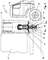
- FIG. 1 shows a side view of a refuse collection vehicle 2 with a driver's cab 3 and a collecting container 6. Behind the driver's cab 3 there is arranged the lift-and-tilt device 10, which is designed as a side loader and above which the pouring opening 6 of the collecting container 4 is located.
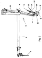
- the lifting and tilting device 10 is fastened to a boom 12 (see FIG. 3) which is designed in the form of an arm which can be moved out of the vehicle 2 in the horizontal direction.
- a boom 12 see FIG. 3 which is designed in the form of an arm which can be moved out of the vehicle 2 in the horizontal direction.
- FIG. 3 only the vehicle frame 8 is shown as a component of the vehicle 2.
- the lifting and tilting device 10 At the free end of the boom 12 is the lifting and tilting device 10, which has two tilting pressure medium cylinders 22 in the upper region. These tilting pressure medium cylinders 22 are articulated on a swivel arm 38, which essentially has two vertically aligned guide rods 15, on which sliding bushes 17 are displaceably mounted. A mounting frame 16 is fastened to these sliding bushes 17 and can be displaced in the vertical direction by means of a stroke pressure medium cylinder 14.
- the receiving device 18 is arranged on the receiving frame 16 in the form of a two-part comb rail 18a, b. An intermediate space 19 is provided between the two elements 18a, b of the receiving device, in which the gripper 24 is in its rest position.
- An abutment 20 is arranged on the receiving frame 16 below the receiving direction and the gripper 24.
- a locking bar 9 is arranged below the tilting pressure medium cylinder 22 and interacts with the receiving device after the receiving device has been raised to fix the received container 1.
- the gripper 24 is - as can be seen in Figures 2 and 3 - pivoted about a horizontal pivot axis 28 so that it can be pivoted away from the rest position shown in Figure 2 from the receiving device to a container 1 to be emptied to the receiving device fetch up.
- a spring 36 is provided on the pivot axis 28, which allows the gripper 24 to pivot back in its extended position when it hits a container to be emptied.
- the gripper 24 in the embodiment shown here consists of a lever which has a short leg 32 and a long leg 34.
- the long leg 34 is bent at a certain angle and carries a finger 26 at its free end for reaching under the container edge 5 (see FIG. 4).
- the short leg 32 is articulated at its free end to a drive device 30 in the form of a pressure medium motor.
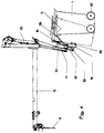
- the gripper 24 is pivoted about its horizontally arranged pivot axis 28, the finger 26 executing a circular movement, as is shown schematically in FIGS. 5a and 5b.
- FIGS. 5a and 5b the two end positions (extended position and rest position) of the gripper 24 are shown. In the rest position, the gripper in the embodiment shown here is located with its long leg 34 behind the receiving device 18, the finger 26 being located slightly above the receiving device 18.
- FIG. 4 The function of the gripper 24 is shown in FIG. 4. In its extended position, the gripper 24 grips the edge 5 of the container 1 to be emptied with its finger 26. Because of its pivoting movement, the container is raised slightly and only has its wheels 40 on the ground. Due to the circular movement of the gripper 24 the edge 5 is raised above the receiving device 18, which is indicated by the broken line of the container 1. If, as shown here in FIG. 4, the gripper 24 is pivotably mounted on the receiving frame 16, it should preferably be spring-mounted in the vertical direction in the region of the pivot axis 28, as shown in FIG. 5b. When the lifting frame 16 is raised, the container then presses the gripper 24 downwards until the receiving device 18 has completely reached under the container edge 5.
- the movement of the gripper 24 is shown schematically in FIG. 5a and in FIG. 5b.
- the finger 26 at the free end of the gripper 24 moves on a circular path K, this circular path being selected such that the finger 26 is above the receiving device 18 when pivoting back so that the container edge can be pulled over the receiving device 18.
- the pivot axis 28 in Figure 5b is resiliently mounted in the vertical direction, so that when the lifting frame 16 is raised, the gripper 24 can move downward under the load of the filled container to be emptied, the Finger 26 leaves the circular path K.
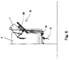
- FIG. 6 shows the tipping position of the container 1.
- the container 1 is held by the receiving device 18 in cooperation with the locking bar 9.
- the gripper 24 is located in the intermediate space 19 between the two elements of the receiving device 18a, 18b.
Landscapes
- Engineering & Computer Science (AREA)
- Mechanical Engineering (AREA)
- Refuse-Collection Vehicles (AREA)
- Load-Engaging Elements For Cranes (AREA)
- Specific Conveyance Elements (AREA)
Applications Claiming Priority (2)
| Application Number | Priority Date | Filing Date | Title |
|---|---|---|---|
| DE19512853A DE19512853C2 (de) | 1995-04-06 | 1995-04-06 | Hubkipp- oder Kippvorrichtung zum Entleeren von Behältern |
| DE19512853 | 1995-04-06 |
Publications (2)
| Publication Number | Publication Date |
|---|---|
| EP0736465A1 true EP0736465A1 (fr) | 1996-10-09 |
| EP0736465B1 EP0736465B1 (fr) | 1998-12-23 |
Family
ID=7758910
Family Applications (1)
| Application Number | Title | Priority Date | Filing Date |
|---|---|---|---|
| EP96105152A Expired - Lifetime EP0736465B1 (fr) | 1995-04-06 | 1996-03-30 | Dispositif de soulèvement/basculement ou de basculement pour le vidage de poubelles |
Country Status (3)
| Country | Link |
|---|---|
| EP (1) | EP0736465B1 (fr) |
| AT (1) | ATE174866T1 (fr) |
| DE (2) | DE19512853C2 (fr) |
Cited By (1)
| Publication number | Priority date | Publication date | Assignee | Title |
|---|---|---|---|---|
| CN103640857A (zh) * | 2013-11-21 | 2014-03-19 | 青岛聚蚨源机电有限公司 | 一种餐厨垃圾处理自动上料设备 |
Families Citing this family (1)
| Publication number | Priority date | Publication date | Assignee | Title |
|---|---|---|---|---|
| DE102004001636B4 (de) * | 2004-01-10 | 2006-12-28 | Hüffermann Entsorgungssysteme GmbH | Entsorgungsfahrzeug |
Citations (3)
| Publication number | Priority date | Publication date | Assignee | Title |
|---|---|---|---|---|
| EP0268883A2 (fr) * | 1986-11-21 | 1988-06-01 | Zöller-Kipper GmbH | Dispositif pour soulever et basculer, ou pour basculer un récipient, en particulier un récipient à ordures, dans le but de le vider dans un réceptacle collecteur |
| EP0463386A1 (fr) * | 1990-06-26 | 1992-01-02 | Antonicelli S.P.A. | Dispositif de basculement de récipients destiné à accrocher automatiquement des poubelles équipées d'un rebord et à les renverser dans la benne d'un véhicule à moteur |
| GB2262730A (en) * | 1991-12-19 | 1993-06-30 | Alec Kenric Marzano | Equipment for handling waste containers. |
Family Cites Families (3)
| Publication number | Priority date | Publication date | Assignee | Title |
|---|---|---|---|---|
| US3016157A (en) * | 1957-12-19 | 1962-01-09 | Lodal Inc | Loader apparatus |
| DE3527022A1 (de) * | 1984-08-21 | 1986-03-06 | Zöller-Kipper GmbH, 6500 Mainz | Kipp- oder hubkipp-vorrichtung zum entleeren von behaeltern in sammelbehaelter, vorzugsweise muellbehaelter in den sammelbehaelter eines muellfahrzeugs |
| DE3631914C1 (de) * | 1986-05-06 | 1987-09-10 | Edelhoff Polytechnik | Muellsammelfahrzeug |
-
1995
- 1995-04-06 DE DE19512853A patent/DE19512853C2/de not_active Expired - Fee Related
-
1996
- 1996-03-30 AT AT96105152T patent/ATE174866T1/de not_active IP Right Cessation
- 1996-03-30 EP EP96105152A patent/EP0736465B1/fr not_active Expired - Lifetime
- 1996-03-30 DE DE59601026T patent/DE59601026D1/de not_active Expired - Fee Related
Patent Citations (3)
| Publication number | Priority date | Publication date | Assignee | Title |
|---|---|---|---|---|
| EP0268883A2 (fr) * | 1986-11-21 | 1988-06-01 | Zöller-Kipper GmbH | Dispositif pour soulever et basculer, ou pour basculer un récipient, en particulier un récipient à ordures, dans le but de le vider dans un réceptacle collecteur |
| EP0463386A1 (fr) * | 1990-06-26 | 1992-01-02 | Antonicelli S.P.A. | Dispositif de basculement de récipients destiné à accrocher automatiquement des poubelles équipées d'un rebord et à les renverser dans la benne d'un véhicule à moteur |
| GB2262730A (en) * | 1991-12-19 | 1993-06-30 | Alec Kenric Marzano | Equipment for handling waste containers. |
Cited By (1)
| Publication number | Priority date | Publication date | Assignee | Title |
|---|---|---|---|---|
| CN103640857A (zh) * | 2013-11-21 | 2014-03-19 | 青岛聚蚨源机电有限公司 | 一种餐厨垃圾处理自动上料设备 |
Also Published As
| Publication number | Publication date |
|---|---|
| DE19512853C2 (de) | 1997-08-21 |
| DE19512853A1 (de) | 1996-10-10 |
| ATE174866T1 (de) | 1999-01-15 |
| DE59601026D1 (de) | 1999-02-04 |
| EP0736465B1 (fr) | 1998-12-23 |
Similar Documents
| Publication | Publication Date | Title |
|---|---|---|
| EP0173180B1 (fr) | Dispositif de basculement ou de soulèvement/basculement pour le vidage de récipients dans des récipients collecteurs, plus spécialement de poubelles dans le récipient collecteur d'un camion de voirie | |
| DE3620610C2 (de) | Greifervorrichtung für Müllbehälter | |
| DE2146653C3 (de) | Einrichtung zum Entleeren von im wesentlichen einen quadratischen oder rechteckigen Grundriß aufweisenden GroOraum-Müllbehältern | |
| EP1077890B1 (fr) | Dispositif de levage et de culbutage | |
| EP0268883B1 (fr) | Dispositif pour soulever et basculer, ou pour basculer un récipient, en particulier un récipient à ordures, dans le but de le vider dans un réceptacle collecteur | |
| DE3830227A1 (de) | Hubkippvorrichtung zum entleeren von behaeltern in die einschuettoeffnung eines sammelbehaelters, insbesondere zum entleeren von muellbehaeltern in den sammelbehaelter eines muellfahrzeuges | |
| DE2606599C2 (de) | Vorrichtung zum Entleeren von Behältern, beispielsweise Müllgefäßen | |
| EP2243727B1 (fr) | Véhicule pour déchets avec dispositif de levage-basculage | |
| DE19512853C2 (de) | Hubkipp- oder Kippvorrichtung zum Entleeren von Behältern | |
| DE4423266C1 (de) | Hubkipp- oder Kippvorrichtung zum Entleeren von Müllbehältern | |
| DE60220758T2 (de) | Müllsammelsystem | |
| EP1619143B1 (fr) | Procédé et dispositif pour sécuriser la zone de travail d'un dispositif de vidange | |
| DE3830989A1 (de) | Hubkippvorrichtung zum entleeren von muellbehaeltern in ein sammelfahrzeug | |
| EP1044146B1 (fr) | Dispositif permettant de vider des poubelles | |
| DE19628224C2 (de) | Vorrichtung zum Entleeren von Müllgroßbehältern | |
| DE19919879C2 (de) | Hubkippvorrichtung | |
| DE20306900U1 (de) | Fahrzeug zum Sammeln und Transportieren von Abfällen mit seitlich angeordneter Ladearmanordnung | |
| EP3315431A1 (fr) | Dispositif de décharge des poubelles | |
| DE2524857B2 (de) | Transport- und Sammelfahrzeug für Schüttgut | |
| DE29823828U1 (de) | Hubvorrichtung zum Aufnehmen und Entleeren von Behältern | |
| DE9313318U1 (de) | Aufnahmegestell für Abfalltonnen | |
| DE4315860C1 (de) | Vorrichtung zum Entleeren eines Umleerbehälters in eine Sammelwanne eines Müllfahrzeuges | |
| DE3831796A1 (de) | Hub- und kippvorrichtung zum anbau an muellpressen, muellfahrzeuge u. dgl. | |
| EP0686581A1 (fr) | Dispositif combiné de verrouillage et d'appui pour poubelles | |
| DE9300699U1 (de) | Anschlagvorrichtung für eine Hubvorrichtung bei einem Hecklade-Abrollkipper-Müllfahrzeug |
Legal Events
| Date | Code | Title | Description |
|---|---|---|---|
| PUAI | Public reference made under article 153(3) epc to a published international application that has entered the european phase |
Free format text: ORIGINAL CODE: 0009012 |
|
| AK | Designated contracting states |
Kind code of ref document: A1 Designated state(s): AT BE CH DE FR GB LI NL |
|
| 17P | Request for examination filed |
Effective date: 19960917 |
|
| GRAG | Despatch of communication of intention to grant |
Free format text: ORIGINAL CODE: EPIDOS AGRA |
|
| 17Q | First examination report despatched |
Effective date: 19980325 |
|
| GRAG | Despatch of communication of intention to grant |
Free format text: ORIGINAL CODE: EPIDOS AGRA |
|
| GRAH | Despatch of communication of intention to grant a patent |
Free format text: ORIGINAL CODE: EPIDOS IGRA |
|
| GRAH | Despatch of communication of intention to grant a patent |
Free format text: ORIGINAL CODE: EPIDOS IGRA |
|
| GRAA | (expected) grant |
Free format text: ORIGINAL CODE: 0009210 |
|
| AK | Designated contracting states |
Kind code of ref document: B1 Designated state(s): AT BE CH DE FR GB LI NL |
|
| REF | Corresponds to: |
Ref document number: 174866 Country of ref document: AT Date of ref document: 19990115 Kind code of ref document: T |
|
| REG | Reference to a national code |
Ref country code: CH Ref legal event code: NV Representative=s name: DIPL.-ING. ETH H. R. WERFFELI PATENTANWALT Ref country code: CH Ref legal event code: EP |
|
| REF | Corresponds to: |
Ref document number: 59601026 Country of ref document: DE Date of ref document: 19990204 |
|
| GBT | Gb: translation of ep patent filed (gb section 77(6)(a)/1977) |
Effective date: 19990203 |
|
| ET | Fr: translation filed | ||
| PLBE | No opposition filed within time limit |
Free format text: ORIGINAL CODE: 0009261 |
|
| STAA | Information on the status of an ep patent application or granted ep patent |
Free format text: STATUS: NO OPPOSITION FILED WITHIN TIME LIMIT |
|
| 26N | No opposition filed | ||
| REG | Reference to a national code |
Ref country code: GB Ref legal event code: IF02 |
|
| PGFP | Annual fee paid to national office [announced via postgrant information from national office to epo] |
Ref country code: GB Payment date: 20020305 Year of fee payment: 7 |
|
| PGFP | Annual fee paid to national office [announced via postgrant information from national office to epo] |
Ref country code: NL Payment date: 20020318 Year of fee payment: 7 Ref country code: FR Payment date: 20020318 Year of fee payment: 7 |
|
| PGFP | Annual fee paid to national office [announced via postgrant information from national office to epo] |
Ref country code: AT Payment date: 20020322 Year of fee payment: 7 |
|
| PGFP | Annual fee paid to national office [announced via postgrant information from national office to epo] |
Ref country code: CH Payment date: 20020325 Year of fee payment: 7 Ref country code: BE Payment date: 20020325 Year of fee payment: 7 |
|
| PGFP | Annual fee paid to national office [announced via postgrant information from national office to epo] |
Ref country code: DE Payment date: 20020506 Year of fee payment: 7 |
|
| PG25 | Lapsed in a contracting state [announced via postgrant information from national office to epo] |
Ref country code: GB Free format text: LAPSE BECAUSE OF NON-PAYMENT OF DUE FEES Effective date: 20030330 Ref country code: AT Free format text: LAPSE BECAUSE OF NON-PAYMENT OF DUE FEES Effective date: 20030330 |
|
| PG25 | Lapsed in a contracting state [announced via postgrant information from national office to epo] |
Ref country code: LI Free format text: LAPSE BECAUSE OF NON-PAYMENT OF DUE FEES Effective date: 20030331 Ref country code: CH Free format text: LAPSE BECAUSE OF NON-PAYMENT OF DUE FEES Effective date: 20030331 Ref country code: BE Free format text: LAPSE BECAUSE OF NON-PAYMENT OF DUE FEES Effective date: 20030331 |
|
| BERE | Be: lapsed |
Owner name: *ZOLLER-KIPPER G.M.B.H. Effective date: 20030331 |
|
| PG25 | Lapsed in a contracting state [announced via postgrant information from national office to epo] |
Ref country code: NL Free format text: LAPSE BECAUSE OF NON-PAYMENT OF DUE FEES Effective date: 20031001 Ref country code: DE Free format text: LAPSE BECAUSE OF NON-PAYMENT OF DUE FEES Effective date: 20031001 |
|
| REG | Reference to a national code |
Ref country code: CH Ref legal event code: PL |
|
| GBPC | Gb: european patent ceased through non-payment of renewal fee |
Effective date: 20030330 |
|
| PG25 | Lapsed in a contracting state [announced via postgrant information from national office to epo] |
Ref country code: FR Free format text: LAPSE BECAUSE OF NON-PAYMENT OF DUE FEES Effective date: 20031127 |
|
| NLV4 | Nl: lapsed or anulled due to non-payment of the annual fee |
Effective date: 20031001 |
|
| REG | Reference to a national code |
Ref country code: FR Ref legal event code: ST |