EP0736683A2 - Dispositif pour relier un système de recirculation de gaz d'échappement à un système d'admission d'un moteur à combustion - Google Patents
Dispositif pour relier un système de recirculation de gaz d'échappement à un système d'admission d'un moteur à combustion Download PDFInfo
- Publication number
- EP0736683A2 EP0736683A2 EP96103707A EP96103707A EP0736683A2 EP 0736683 A2 EP0736683 A2 EP 0736683A2 EP 96103707 A EP96103707 A EP 96103707A EP 96103707 A EP96103707 A EP 96103707A EP 0736683 A2 EP0736683 A2 EP 0736683A2
- Authority
- EP
- European Patent Office
- Prior art keywords
- connecting flange
- receptacle
- exhaust gas
- gas recirculation
- suction system
- Prior art date
- Legal status (The legal status is an assumption and is not a legal conclusion. Google has not performed a legal analysis and makes no representation as to the accuracy of the status listed.)
- Ceased
Links
- 238000002485 combustion reaction Methods 0.000 title claims abstract description 6
- 238000003780 insertion Methods 0.000 claims description 3
- 230000037431 insertion Effects 0.000 claims description 3
- 239000007789 gas Substances 0.000 description 15
- 238000011161 development Methods 0.000 description 1
- 230000018109 developmental process Effects 0.000 description 1
- 239000003344 environmental pollutant Substances 0.000 description 1
- 239000000463 material Substances 0.000 description 1
- 231100000719 pollutant Toxicity 0.000 description 1
- 230000001105 regulatory effect Effects 0.000 description 1
Images

Classifications
-
- F—MECHANICAL ENGINEERING; LIGHTING; HEATING; WEAPONS; BLASTING
- F02—COMBUSTION ENGINES; HOT-GAS OR COMBUSTION-PRODUCT ENGINE PLANTS
- F02M—SUPPLYING COMBUSTION ENGINES IN GENERAL WITH COMBUSTIBLE MIXTURES OR CONSTITUENTS THEREOF
- F02M35/00—Combustion-air cleaners, air intakes, intake silencers, or induction systems specially adapted for, or arranged on, internal-combustion engines
- F02M35/10—Air intakes; Induction systems
- F02M35/10091—Air intakes; Induction systems characterised by details of intake ducts: shapes; connections; arrangements
- F02M35/10144—Connections of intake ducts to each other or to another device
-
- F—MECHANICAL ENGINEERING; LIGHTING; HEATING; WEAPONS; BLASTING
- F02—COMBUSTION ENGINES; HOT-GAS OR COMBUSTION-PRODUCT ENGINE PLANTS
- F02M—SUPPLYING COMBUSTION ENGINES IN GENERAL WITH COMBUSTIBLE MIXTURES OR CONSTITUENTS THEREOF
- F02M26/00—Engine-pertinent apparatus for adding exhaust gases to combustion-air, main fuel or fuel-air mixture, e.g. by exhaust gas recirculation [EGR] systems
- F02M26/12—Engine-pertinent apparatus for adding exhaust gases to combustion-air, main fuel or fuel-air mixture, e.g. by exhaust gas recirculation [EGR] systems characterised by means for attaching parts of an EGR system to each other or to engine parts
-
- F—MECHANICAL ENGINEERING; LIGHTING; HEATING; WEAPONS; BLASTING
- F02—COMBUSTION ENGINES; HOT-GAS OR COMBUSTION-PRODUCT ENGINE PLANTS
- F02M—SUPPLYING COMBUSTION ENGINES IN GENERAL WITH COMBUSTIBLE MIXTURES OR CONSTITUENTS THEREOF
- F02M26/00—Engine-pertinent apparatus for adding exhaust gases to combustion-air, main fuel or fuel-air mixture, e.g. by exhaust gas recirculation [EGR] systems
- F02M26/13—Arrangement or layout of EGR passages, e.g. in relation to specific engine parts or for incorporation of accessories
- F02M26/17—Arrangement or layout of EGR passages, e.g. in relation to specific engine parts or for incorporation of accessories in relation to the intake system
- F02M26/21—Arrangement or layout of EGR passages, e.g. in relation to specific engine parts or for incorporation of accessories in relation to the intake system with EGR valves located at or near the connection to the intake system
-
- F—MECHANICAL ENGINEERING; LIGHTING; HEATING; WEAPONS; BLASTING
- F02—COMBUSTION ENGINES; HOT-GAS OR COMBUSTION-PRODUCT ENGINE PLANTS
- F02M—SUPPLYING COMBUSTION ENGINES IN GENERAL WITH COMBUSTIBLE MIXTURES OR CONSTITUENTS THEREOF
- F02M35/00—Combustion-air cleaners, air intakes, intake silencers, or induction systems specially adapted for, or arranged on, internal-combustion engines
- F02M35/10—Air intakes; Induction systems
- F02M35/10209—Fluid connections to the air intake system; their arrangement of pipes, valves or the like
- F02M35/10222—Exhaust gas recirculation [EGR]; Positive crankcase ventilation [PCV]; Additional air admission, lubricant or fuel vapour admission
-
- F—MECHANICAL ENGINEERING; LIGHTING; HEATING; WEAPONS; BLASTING
- F02—COMBUSTION ENGINES; HOT-GAS OR COMBUSTION-PRODUCT ENGINE PLANTS
- F02M—SUPPLYING COMBUSTION ENGINES IN GENERAL WITH COMBUSTIBLE MIXTURES OR CONSTITUENTS THEREOF
- F02M26/00—Engine-pertinent apparatus for adding exhaust gases to combustion-air, main fuel or fuel-air mixture, e.g. by exhaust gas recirculation [EGR] systems
- F02M26/65—Constructional details of EGR valves
- F02M26/70—Flap valves; Rotary valves; Sliding valves; Resilient valves
-
- F—MECHANICAL ENGINEERING; LIGHTING; HEATING; WEAPONS; BLASTING
- F05—INDEXING SCHEMES RELATING TO ENGINES OR PUMPS IN VARIOUS SUBCLASSES OF CLASSES F01-F04
- F05C—INDEXING SCHEME RELATING TO MATERIALS, MATERIAL PROPERTIES OR MATERIAL CHARACTERISTICS FOR MACHINES, ENGINES OR PUMPS OTHER THAN NON-POSITIVE-DISPLACEMENT MACHINES OR ENGINES
- F05C2225/00—Synthetic polymers, e.g. plastics; Rubber
- F05C2225/08—Thermoplastics
Definitions
- the invention is based on a device for connecting an exhaust gas recirculation valve to an intake system of an internal combustion engine according to the preamble of the main claim.
- Exhaust gas recirculation systems are used in internal combustion engines, in particular in gasoline engines, to reduce the emission of the pollutants emitted by the exhaust gas.
- the exhaust gas recirculation systems have an exhaust gas recirculation line that returns exhaust gases from the exhaust pipe to an intake system.
- the exhaust gas recirculation line is equipped with a throttle valve, which serves as a metering device for the exhaust gas recirculation flow.
- Swivel or bayonet connections are known in the art as connecting devices, the connection being achieved by axially plugging them together and then rotating them radially.
- Part of the connection has a pin that is in a to be connected Partly arranged slot or backdrop engages.
- the connection is created after the parts have been turned radially. In order to avoid an independent loosening during operation, an additional securing by positive and / or non-positive connection is provided.
- the device according to the invention with the characterizing features of the main claim has the advantage that an inexpensive, reliable and space-saving connection is created between the exhaust gas recirculation line and the suction system, which moreover allows easy assembly and disassembly of the connection. Simple and quick disassembly is becoming increasingly important in automotive engineering with regard to the recyclability of the components.
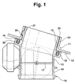
- FIG. 1 shows a sectional view through a connection point of an exhaust gas recirculation valve with an intake manifold of an intake system
- FIG. 2 shows a connection flange of the exhaust gas recirculation valve
- FIG. 3 shows a detail of a receptacle for the connection flange in the intake system with a backdrop inserted therein.
- FIG. 1 shows the connection of an exhaust gas recirculation line 10 with a suction system 11 of an internal combustion engine.
- a throttle valve 13 is shown as exhaust gas recirculation line 10 in the present exemplary embodiment.
- the throttle valve 13 has a circular feed section 14 and a likewise circular connection flange 15.
- a pivotably mounted throttle valve 17 is arranged, with which the exhaust gas recirculation flow is regulated.
- the connecting flange 15 is designed on the outer surface with a circumferential collar 18, wherein a circumferential recess 19 is formed in the collar 18 and serves to receive an elastically deformable seal 20.
- the suction system 11 is, for example, a suction pipe with a receptacle 24 which has a circular opening 25 with an end face 12 facing the connecting flange 15.
- the connecting flange 15 of the throttle valve 13 is received by the opening 25, the outer diameter of the connecting flange 15 and the inner diameter of the opening 25 being dimensioned such that the connecting flange 15 is received by the opening 25 with almost no play.
- the connecting flange 15 has, on the outer lateral surface, radially uniformly distributed webs 21 which extend in the axial direction.
- the webs are used so that the connecting flange 15 is not tilted when inserted into the opening 25 and is guided in the opening 25 so that it can rotate easily.
- Pins 27 are also formed on the outer lateral surface of the connecting flange 15, three pins 27 being provided in the present exemplary embodiment.
- the pins 27 are designed, for example, as quadrilaterals and have two inclined sides running parallel to one another in the radial direction (FIG. 2).
- a link 30 is formed in the inner wall of the receptacle 24 for each pin 27 of the connecting flange 15.
- the scenes 30 each have an open and axially extending insertion section 31 pointing towards the connecting flange 15, a clamping section 32 which extends inclined in the radial direction and a securing section 33 which extends in the axial direction and is directed counter to the bevel of the clamping section 32.
- the seal 20 is first inserted into the recess 19 of the collar 18.
- the seal 20 is dimensioned so that it protrudes beyond the end face of the collar 18.
- the connecting flange 15 of the throttle valve 13 is now inserted into the opening 25 of the receptacle 24, the pins 27 being inserted into the insertion sections 31 and being guided in the axial direction into the clamping sections 33.
- either the throttle valve 13 or the corresponding section of the suction system 11 is moved radially in such a way that the pins 27 move in the clamping sections 32 of the links 30 up to the securing section 34.
- the suction system 11 and the throttle valve 13 are made of plastic in the present exemplary embodiment. However, any other combination of materials is also conceivable.
- the device according to the invention is also conceivable for other connections in automotive engineering, in which a quick assembly and / or disassembly of the parts to be connected is required and, moreover, the connection has to withstand a vibration load.
Landscapes
- Engineering & Computer Science (AREA)
- Chemical & Material Sciences (AREA)
- Combustion & Propulsion (AREA)
- Mechanical Engineering (AREA)
- General Engineering & Computer Science (AREA)
- Exhaust-Gas Circulating Devices (AREA)
- Control Of Throttle Valves Provided In The Intake System Or In The Exhaust System (AREA)
Applications Claiming Priority (2)
| Application Number | Priority Date | Filing Date | Title |
|---|---|---|---|
| DE19512941A DE19512941C2 (de) | 1995-04-06 | 1995-04-06 | Vorrichtung zum Verbinden eines Abgasrückführsystems mit einer Sauganlage eines Verbrennungsmotors |
| DE19512941 | 1995-04-06 |
Publications (2)
| Publication Number | Publication Date |
|---|---|
| EP0736683A2 true EP0736683A2 (fr) | 1996-10-09 |
| EP0736683A3 EP0736683A3 (fr) | 1997-04-09 |
Family
ID=7758970
Family Applications (1)
| Application Number | Title | Priority Date | Filing Date |
|---|---|---|---|
| EP96103707A Ceased EP0736683A3 (fr) | 1995-04-06 | 1996-03-09 | Dispositif pour relier un système de recirculation de gaz d'échappement à un système d'admission d'un moteur à combustion |
Country Status (2)
| Country | Link |
|---|---|
| EP (1) | EP0736683A3 (fr) |
| DE (1) | DE19512941C2 (fr) |
Cited By (6)
| Publication number | Priority date | Publication date | Assignee | Title |
|---|---|---|---|---|
| WO2001023738A1 (fr) * | 1999-09-24 | 2001-04-05 | Filterwerk Mann+Hummel Gmbh | Systeme pour introduire un fluide chaud dans une structure creuse |
| US6299661B1 (en) | 1999-05-12 | 2001-10-09 | Siemens Canada Limited | Twist fit connection for air cleaners |
| EP1207295A1 (fr) * | 2000-11-17 | 2002-05-22 | Siemens Canada Limited | Accouplement par encliquetage à rotation pour filtres à air |
| EP1167740A3 (fr) * | 2000-07-01 | 2002-12-18 | Pierburg GmbH | Dispositif de séparation de fluides |
| GB2478008A (en) * | 2010-02-23 | 2011-08-24 | Gm Global Tech Operations Inc | Cylinder head with an integral turbine housing |
| GB2484481A (en) * | 2010-10-12 | 2012-04-18 | Gm Global Tech Operations Inc | EGR valve assembly for internal combustion engines |
Families Citing this family (2)
| Publication number | Priority date | Publication date | Assignee | Title |
|---|---|---|---|---|
| DE19903832A1 (de) * | 1999-02-01 | 2000-08-03 | Mahle Filtersysteme Gmbh | Einrichtung zur insbesondere lösbaren Befestigung zwischen zwei mit einem Fluid befüllbaren Teilen eines Kraftfahrzeuges |
| DE102007056647A1 (de) | 2007-11-24 | 2009-05-28 | Dr. Ing. H.C. F. Porsche Aktiengesellschaft | Anbindung zweier Ansaugverteiler an ein Verteilerrohr |
Family Cites Families (6)
| Publication number | Priority date | Publication date | Assignee | Title |
|---|---|---|---|---|
| DE3509774A1 (de) * | 1985-03-19 | 1986-10-02 | Witzenmann GmbH, Metallschlauch-Fabrik Pforzheim, 7530 Pforzheim | Rohrverbindung |
| DE3726332C1 (de) * | 1987-08-07 | 1988-06-23 | Bayerische Motoren Werke Ag | Ansaugleitungsteil einer Brennkraftmaschine |
| US5201549A (en) * | 1992-01-17 | 1993-04-13 | Senior Engineering Investments, B.V. | Thermal isolation coupling system |
| DE4310510C2 (de) * | 1993-03-31 | 1995-04-20 | Freudenberg Carl Fa | Faltenbalg |
| FR2706976B1 (fr) * | 1993-06-25 | 1995-10-20 | Solvay | |
| US5425347A (en) * | 1994-03-21 | 1995-06-20 | Bundy Corporation | Connector for exhaust gas recirculation tube |
-
1995
- 1995-04-06 DE DE19512941A patent/DE19512941C2/de not_active Expired - Fee Related
-
1996
- 1996-03-09 EP EP96103707A patent/EP0736683A3/fr not_active Ceased
Cited By (10)
| Publication number | Priority date | Publication date | Assignee | Title |
|---|---|---|---|---|
| US6299661B1 (en) | 1999-05-12 | 2001-10-09 | Siemens Canada Limited | Twist fit connection for air cleaners |
| WO2001023738A1 (fr) * | 1999-09-24 | 2001-04-05 | Filterwerk Mann+Hummel Gmbh | Systeme pour introduire un fluide chaud dans une structure creuse |
| US6672292B2 (en) | 1999-09-24 | 2004-01-06 | Filterwerk Mann & Hummel Gmbh | Fluid inlet for introducing a hot fluid into a hollow structure |
| EP1167740A3 (fr) * | 2000-07-01 | 2002-12-18 | Pierburg GmbH | Dispositif de séparation de fluides |
| EP1207295A1 (fr) * | 2000-11-17 | 2002-05-22 | Siemens Canada Limited | Accouplement par encliquetage à rotation pour filtres à air |
| GB2478008A (en) * | 2010-02-23 | 2011-08-24 | Gm Global Tech Operations Inc | Cylinder head with an integral turbine housing |
| GB2478008B (en) * | 2010-02-23 | 2014-10-08 | Gm Global Tech Operations Inc | Cylinder head with an integral turbine housing |
| GB2484481A (en) * | 2010-10-12 | 2012-04-18 | Gm Global Tech Operations Inc | EGR valve assembly for internal combustion engines |
| US8763592B2 (en) | 2010-10-12 | 2014-07-01 | GM Global Technology Operations LLC | EGR valve assembly for internal combustion engines |
| GB2484481B (en) * | 2010-10-12 | 2015-03-04 | Gm Global Tech Operations Inc | EGR valve assembly for internal combustion engines |
Also Published As
| Publication number | Publication date |
|---|---|
| DE19512941C2 (de) | 1997-02-20 |
| EP0736683A3 (fr) | 1997-04-09 |
| DE19512941A1 (de) | 1996-10-24 |
Similar Documents
| Publication | Publication Date | Title |
|---|---|---|
| EP1255038B1 (fr) | Système d'injection de carburant | |
| DE19745388A1 (de) | Kraftstoffzufuhrvorrichtung mit einem Element zum Verhindern eines Herausrutschens und Verfahren zum Zusammenbau derselben | |
| EP1332285B1 (fr) | Installation d'injection de carburant | |
| EP0771393A1 (fr) | Dispositif permettant d'alimenter un moteur a combustion interne en carburant provenant d'un reservoir | |
| DE19636579B4 (de) | Ansaugvorrichtung für mehrzylindrige Verbrennungsmotoren | |
| DE19512941C2 (de) | Vorrichtung zum Verbinden eines Abgasrückführsystems mit einer Sauganlage eines Verbrennungsmotors | |
| EP1448886A1 (fr) | Manchon de blocage pour systeme d'injection de combustible | |
| DE19960223A1 (de) | Saugmodul für eine Brennkraftmaschine | |
| DE19902186A1 (de) | Brennstoffeinspritzvorrichtung | |
| DE19637276A1 (de) | Kraftstoffördereinrichtung für Kraftfahrzeuge | |
| EP1373707A1 (fr) | Raccord pour raccorder une conduite de carburant a une soupape d'injection de carburant | |
| EP1283351B1 (fr) | Système d'admission pour un moteur à combustion interne | |
| DE19857474A1 (de) | Montagevorrichtung zur Montage und Demontage eines Brennstoffeinspritzventils | |
| WO1989012162A1 (fr) | Injecteur de carburant pour moteurs a combustion interne | |
| EP0688396A1 (fr) | Raccordement de conduite haute pression | |
| DE4320925A1 (de) | Druckregler für Kraftstoff-Einspritzanlagen | |
| DE10115325A1 (de) | Kraftstoff-Einspritzvorrichtung, insbesondere Injektor, für Brennkraftmaschinen | |
| DE10013706C1 (de) | Vorrichtung zur Anbringung eines luftführenden Leitungselements an einem Luftfilterelement | |
| DE102014109247B4 (de) | Modular aufgebautes Regelventil | |
| DE3202405C2 (de) | Kraftstoffeinspritzpumpe für Brennkraftmaschinen | |
| DE3844371A1 (de) | Kraftstoff-einspritzduese fuer brennkraftmaschinen | |
| DE19651188C2 (de) | Kraftstoffversorgungseinheit | |
| DE19818585C1 (de) | Vorrichtung zum Verbinden eines Krümmerrohres einer Auspuffanlage mit dem Zylinderkopf | |
| DE102025113360A1 (de) | Expansionsventil | |
| EP4269777A1 (fr) | Culasse pour un moteur à combustion interne |
Legal Events
| Date | Code | Title | Description |
|---|---|---|---|
| PUAI | Public reference made under article 153(3) epc to a published international application that has entered the european phase |
Free format text: ORIGINAL CODE: 0009012 |
|
| AK | Designated contracting states |
Kind code of ref document: A2 Designated state(s): DE FR GB IT |
|
| PUAL | Search report despatched |
Free format text: ORIGINAL CODE: 0009013 |
|
| AK | Designated contracting states |
Kind code of ref document: A3 Designated state(s): DE FR GB IT |
|
| 17P | Request for examination filed |
Effective date: 19971009 |
|
| 17Q | First examination report despatched |
Effective date: 19980121 |
|
| STAA | Information on the status of an ep patent application or granted ep patent |
Free format text: STATUS: THE APPLICATION HAS BEEN REFUSED |
|
| 18R | Application refused |
Effective date: 19991127 |