EP0736698B1 - Spannratsche - Google Patents
Spannratsche Download PDFInfo
- Publication number
- EP0736698B1 EP0736698B1 EP96103393A EP96103393A EP0736698B1 EP 0736698 B1 EP0736698 B1 EP 0736698B1 EP 96103393 A EP96103393 A EP 96103393A EP 96103393 A EP96103393 A EP 96103393A EP 0736698 B1 EP0736698 B1 EP 0736698B1
- Authority
- EP
- European Patent Office
- Prior art keywords
- ratchet
- tightening
- base body
- slide
- shaft
- Prior art date
- Legal status (The legal status is an assumption and is not a legal conclusion. Google has not performed a legal analysis and makes no representation as to the accuracy of the status listed.)
- Expired - Lifetime
Links
- 238000006073 displacement reaction Methods 0.000 claims description 3
- 230000000284 resting effect Effects 0.000 claims 2
- 238000004804 winding Methods 0.000 description 14
- 230000002349 favourable effect Effects 0.000 description 3
- 238000004519 manufacturing process Methods 0.000 description 3
- 238000010276 construction Methods 0.000 description 2
- 230000002411 adverse Effects 0.000 description 1
- 239000007787 solid Substances 0.000 description 1
- 230000000087 stabilizing effect Effects 0.000 description 1
- 239000004753 textile Substances 0.000 description 1
Images

Classifications
-
- B—PERFORMING OPERATIONS; TRANSPORTING
- B60—VEHICLES IN GENERAL
- B60P—VEHICLES ADAPTED FOR LOAD TRANSPORTATION OR TO TRANSPORT, TO CARRY, OR TO COMPRISE SPECIAL LOADS OR OBJECTS
- B60P7/00—Securing or covering of load on vehicles
- B60P7/06—Securing of load
- B60P7/08—Securing to the vehicle floor or sides
- B60P7/0823—Straps; Tighteners
- B60P7/083—Tensioning by repetetive movement of an actuating member
-
- Y—GENERAL TAGGING OF NEW TECHNOLOGICAL DEVELOPMENTS; GENERAL TAGGING OF CROSS-SECTIONAL TECHNOLOGIES SPANNING OVER SEVERAL SECTIONS OF THE IPC; TECHNICAL SUBJECTS COVERED BY FORMER USPC CROSS-REFERENCE ART COLLECTIONS [XRACs] AND DIGESTS
- Y10—TECHNICAL SUBJECTS COVERED BY FORMER USPC
- Y10T—TECHNICAL SUBJECTS COVERED BY FORMER US CLASSIFICATION
- Y10T24/00—Buckles, buttons, clasps, etc.
- Y10T24/21—Strap tighteners
-
- Y—GENERAL TAGGING OF NEW TECHNOLOGICAL DEVELOPMENTS; GENERAL TAGGING OF CROSS-SECTIONAL TECHNOLOGIES SPANNING OVER SEVERAL SECTIONS OF THE IPC; TECHNICAL SUBJECTS COVERED BY FORMER USPC CROSS-REFERENCE ART COLLECTIONS [XRACs] AND DIGESTS
- Y10—TECHNICAL SUBJECTS COVERED BY FORMER USPC
- Y10T—TECHNICAL SUBJECTS COVERED BY FORMER US CLASSIFICATION
- Y10T24/00—Buckles, buttons, clasps, etc.
- Y10T24/21—Strap tighteners
- Y10T24/2175—Cargo tie down
Definitions
- the present invention relates to a tensioning ratchet for a lashing cord with the features of the preamble of claim 1.
- a tensioning ratchet is known, for example, from US Pat EP-A-0 455 085.
- the invention is based on the object to make a generic ratchet as flat as possible.
- the generic ratchet shape that the two locking slide relative to the ratchet each other are arranged diametrically opposite and that the direction of displacement the gate valve with the central longitudinal direction of the ratchet body in is essentially congruent.
- the invention is based on the consideration that in the generic ratchet primarily through the slides arranged one above the other the disturbing overall height cause. A strong curvature of the slide could Reduction in overall height would contribute to the rest Adversely affect the functional properties of the ratchet.
- ratchet width can be larger with a smaller ratchet Ratchet length should be chosen as for ratchets for large belt widths.
- the opposite straight slider according to the invention have the advantage that they are only moved in translation and not in rotation have to. This is especially true for small slide sizes for small ones
- Ratchets are an advantage. In particular, it only favors translational Slide movement the sliding behavior of the slide. In addition, by a purely translational slide movement effectively tilting the slide prevented. Finally, it is favorable to use the gate valve in the longitudinal direction of the basic body, because in principle the entire basic body length as Travel path for the slide is usable. Because the sliders are very flat and accordingly, their guides have a very low internal height the entire ratchet body can be made very flat. It is also advantageous that the gradual relaxation of the Locked the locking force caused by the slide by 180 ° attacks offset on the ratchet.
- the locking forces of the locking slide are therefore wide distributed over the circumference of the ratchet wheel.
- the subject of claim 2 is a material-saving and easy to manufacturing embodiment of the base body.
- one Basic gate valve - as is generally known for ratchets - in Base body stored next to the or the ratchet wheels.
- second fork gate valve is in fork-like extensions Basic body side walls on the side facing away from the basic gate valve of the ratchet.
- Claims 4-6 relate to an advantageous one Tension lever-cam combination, with which the lashing string is simple on the one hand and can be tensioned efficiently and on the other hand can be solved step by step.
- Claims 7 to 9 relate to a structurally simple and favorable construction of the tensioning lever.
- the the Handle bridging the clamping lever side walls has the double function of a Handle on the one hand and a stabilizing cross connection of the Clamp lever side walls on the other hand.
- the tension lever is open this way very filigree and advantageously reduces the tension lever's own weight.
- the claims 10 to 12 teach the structurally simple and favorable construction of the ratchet body. Of the Basic body has a low weight in this way, what especially advantageous for the small ratchets of interest here is. Due to the fork-like design of both body free ends, on the one hand the fixed end of the lashing string easily fixable to the console and on the other hand the winding shaft can be easily mounted on the base body.
- the symmetrical structure of the ratchet according to claim 12 advantageous. As a result of symmetry, numerous identical parts can also be installed, which the Manufacturing costs for the tensioning ratchet are reduced.
- the symmetrical Structure of the tensioning ratchet with a symmetrical force distribution when applied Lashing tension is provided.
- claims 13 and 14 serve to prevent a accidental overtightening of the tensioning lever in the tensioning direction from Erroneous clamping area in the release area.
- the features of claims 15 to 18 serve to further improve the safety of use and Ease of use of the ratchet.
- the tension lever must be released the lashing tension can only be pivoted into the release area and back and forth between the limit stops of the release area will. Each time the actuator slide hits one of the two Limit stops rotates the take-up shaft by half Tooth division back against the clamping direction, which is a gradual Relaxation of the lashing line causes.
- the locking slide are easy longitudinally movable between their extreme positions. Furthermore, with the so designed gate valve high forces transferable. After all, they are Gate valve in the guide slots in the base body and easy to assemble form a solid and permanent form fit with the body.
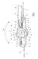
- the tensioning ratchet 2 extending in the longitudinal direction 1 consists of essentially from the base body 3, the winding shaft 4, two on the Rewinder shaft 4 ratchet wheels 5 fixed on the edge and at the Winding shaft 4 pivotally mounted tension lever 6.
- the lashing strap 7 is with its fixed end designed as a belt loop 8 on the bolt 9 attached.
- the bolt 9 passes through and bridges the two Base body side walls 10 in the direction perpendicular to the central longitudinal direction 1 transverse direction.
- On the body side walls 10 are in addition to the Winding shaft 4 in the longitudinal direction 1, the fork-like extensions 11 molded.
- guide slots 12 for the Basic gate valve 13 In the body side walls 10 are guide slots 12 for the Basic gate valve 13 molded. Analogous to this are guide slots 12 in the fork-like extensions 11 for mounting the fork lock slide 14 brought in.
- the basic gate valve 13 and the fork gate valve 14 are in Central longitudinal direction 1 translationally against a spring assembly 15 slidable.
- the tensioning lever 6 has on its winding shaft 4 facing away Free end of the handle 16.
- the one also engaging in the ratchet wheel 5 Drive slide 18 is slidably mounted in the slide guide slot 17.
- the loose end of the lashing strap 7 is fixed in the two-part winding shaft 4.
- the drive slide 18 engages behind one Ratchet tooth 19 of the ratchet wheel 5.
- Tensioning lever 6 is pivoted in the pivoting direction 20 until it reaches its position in FIG. 2 extreme swivel position shown has reached.
- the swivel direction 20 of the clamping lever 6 corresponds to the direction of rotation of the ratchet wheel 5 or Tensioning direction of the winding shaft 4.
- the clamping lever 6 against the pivoting direction 20 on the base body 2 pivoted back into its rest position shown in Fig. 1.
- the Drive slide 18 slides over the rounded front Tooth flanks 21 of the ratchet teeth 19 without a corresponding rotation of the Locking wheels 5.
- the tensioning lever 6 is then shown in FIG. 1 Rest position in turn in the direction 20 in its shown in Fig. 2 Swiveled position swiveled.
- the drive slide 18 engages behind the the straight tooth flank 22 facing away from the rounded tooth flank 21 Ratchet tooth 19 and in turn drives both the ratchet wheel 5 and the so non-rotatably connected drive shaft 4 in the direction of rotation 20 identical clamping direction.
- the tensioning lever 6 is over in the pivoting direction 20 its clamping position shown in Fig. 2 can also be pivoted.
- the tensioning lever 6 over that shown in Fig. 2 Clamping position also gets the unlocking curve 23 on the Handle 16 facing away from the tension lever bearing end 24 with the Basic gate valve 13 engages in such a way that the main gate valve 13 against move the spring assembly 15 in the guide slot 12 in the central longitudinal direction 1 will (Fig. 3).
- the winding end 27 is the end of the belt loop 8 facing away from the Lashing straps 7.
- the drive slide 18 in the tensioning lever 6 lies in the one shown in FIG. 2 Clamping position on the clamping stop 28 on the base body 3.
- To the Swiveling the tensioning lever 6 into that shown in FIGS. 3, 4 and 5 Release position is the drive slide 18 over the clamping stop 28 can be lifted and slides with its end face on the slide guide 29 effective, the clamping stop 28 adjacent in the pivoting direction 20 Area.
Landscapes
- Engineering & Computer Science (AREA)
- Transportation (AREA)
- Mechanical Engineering (AREA)
- Basic Packing Technique (AREA)
- Materials For Medical Uses (AREA)
- Polysaccharides And Polysaccharide Derivatives (AREA)
- Package Frames And Binding Bands (AREA)
Description
EP-A-0 455 085.
- Fig. 1
- eine Seitenansicht der erfindungsmäßigen Spannratsche,
- Fig. 2
- eine Seitenansicht des Zahnrichtgesperres und des Antriebszahnrichtgesperres in der Endposition des vom Grundkörper weggeschwenkten Spannhebels beim Spannen des Zurrstrangs,
- Fig. 3
- eine Seitenansicht des Zahnrichtgesperres und des Antriebszahnrichtgesperres in der ersten Lösestellung bei durch die Entriegelungskurve ausgerücktem Grundsperrschieber,
- Fig. 4
- eine Seitenansicht des Zahnrichtgesperres und des Antriebszahnrichtgesperres in einer zweiten Lösestellung bei durch die Entriegelungsnocke ausgerücktem Gabelsperrschieber,
- Fig. 5
- die totale Lösestellung der Spannratsche bei sowohl von der Entriegelungsnocke ausgerücktem Gabelsperrschieber als auch durch die Lösenocke ausgerücktem Grundsperrschieber.
- 1
- Mittellängsrichtung
- 2
- Spannratsche
- 3
- Grundkörper
- 4
- Aufwickelwelle
- 5
- Sperrad
- 6
- Spannhebel
- 7
- Zurrgurt
- 8
- Gurtschlaufe
- 9
- Schraubbolzen
- 10
- Grundkörperseitenwand
- 11
- gabelartige Verlängerung
- 12
- Führungsschlitz
- 13
- Grundsperrschieber
- 14
- Gabelsperrschieber
- 15
- Federpaket
- 16
- Handgriff
- 17
- Schieberführungsschlitz
- 18
- Antriebsschieber
- 19
- Sperrzahn
- 20
- Schwenkrichtung
- 21
- gerundete Zahnflanke
- 22
- gerade Zahnflanke
- 23
- Entriegelungskurve
- 24
- Spannhebellagerende
- 25
- Entriegelungsnocke
- 26
- Lösenocke
- 27
- Aufwickelende
- 28
- Spannanschlag
- 29
- Gleifführung
Claims (22)
- Spannratsche (2) für einen Zurrstrang (7)mit einer an einem Grundkörper (3) gelagerten und drehantreibbaren Aufwickelwelle (4),mit einem lösbaren Zahnrichtgesperre zwischen Grundkörper (3) und Aufwickelwelle (4) zur Sicherung gegen ein Rückdrehen der Aufwickelwelle (4) beim Spannen im wesentlichen gebildet ausdadurch gekennzeichnet,einem an der Aufwickelwelle (4) drehfest gelagerten Sperrad (5) mit einer Verzahnung (19) undzwei in jeweils separaten Führungen (12) im Grundkörper (3) längsverschiebbar gelagerten und abwechselnd in die Verzahnung (19) eingreifenden Sperrschiebern (13,14),daß die beiden Sperrschieber (13,14) bezogen auf das Sperrad (5) einander diametral gegenüberliegen unddaß die Verschieberichtung der Sperrschieber (13,14) mit der Mittellängsrichtung (1) des Grundkörpers (3) im wesentlichen kongruent ist.
- Spannratsche nach Anspruch 1,
dadurch gekennzeichnet,daß der Grundkörper (3) im wesentlichen U-förmig ist,daß die U-Schenkel die zueinander parallelen Grundkörperseitenwände (10) bilden,daß die Aufwickelwelle (4) an einem Ende des Grundkörpers (3) in Augen in den Grundkörperseitenwänden (10) gelagert ist,daß die Grundkörperseitenwände am Aufwickelwellenende des Grundkörpers (3) über die Augen hinaus gabelartig verlängert sind unddaß in den Grundkörperseitenwänden Führungsschlitze (12) für den Grundsperrschieber (13) und in den gabelartien Verlängerungen (11) Führungsschlitze (12) für den Gabelsperrschieber (14) eingeformt sind. - Spannratsche nach Anspruch 2,
dadurch gekennzeichnet,
daß der Grundsperrschieber (13) und der Gabelsperrschieber (14) sich gleichebig zueinander bewegen. - Spannratsche nach einem oder mehreren der vorhergehenden Ansprüche,
gekennzeichnet durchdurch einen auf der Aufwickelwelle (4) schwenkbar gelagerten Spannhebel (6) undein zwischen Spannhebel (6) und Aufwickelwelle (4) wirksames Antriebs-Zahnrichtgesperre zum Wellendrehantrieb mittels eines am Spannhebel (6) in Führungsschlitzen (17) längsverschiebbar gelagerten und in die Verzahnung (19) des Sperrades (5) eingreifenden Antriebsschiebers (18). - Spannratsche nach Anspruch 4,
dadurch gekennzeichnet,daß der Spannhebel (6) am Umfang seines Lagerendes (24) eine Entriegelungsnocke (25) zum Ausrücken des Gabelsperrschiebers (14) trägt,daß in Umfangsrichtung neben der Entriegelungsnocke (25) um einen Winkel α von etwa 150° versetzt eine den Grundsperrschieber (13) beaufschlagende Entriegelungskurve (23) angeordnet ist derart, daß durch Hin- und Herschwenken des Spannhebels (6) der Gabelsperrschieber (14) und der Grundsperrschieber (13) alternierend aus der Sperradverzahnung (19) ausrückbar sind unddaß in Umfangsrichtung neben der Entriegelungsnocke (25) um einen Winkel β von etwa 180° bis 200° versetzt eine den Grundsperrschieber (13) dauerhaft aus der Sperradverzahnung (19) ausrückende Lösenocke (26) angeordnet ist derart, daß bei Beaufschlagung des Grundsperrschiebers (13) mit der Lösenocke (26) der Gabelsperrschieber (14) von der Entriegelungsnocke (25) beaufschlagt ebenfalls aus der Sperradverzahnung (19) ausgerückt ist. - Spannratsche nach Anspruch 5,
dadurch gekennzeichnet,
daß die Entriegelungskurve (23) der Entriegelungsnocke (25) in Spannrichtung (20) vorauseilend benachbart am Umfang des Spannhebellagerendes (24) angeordnet ist und daß die Entriegelungskurve (23) der Lösenocke (26) in Spannrichtung (20) vorauseilend benachbart am Umfang des Spannhebellagerendes (24) angeordnet ist und daß die Entriegelungskurve (23) und die Lösenocke (26) der Entriegelungsnocke (25) in Spannrichtung (20) vorauseilend am Umfang des Spannhebellagerendes (24) angeordnet sind. - Spannratsche nach einem oder mehreren der vorhergehenden Ansprüche,
dadurch gekennzeichnet,
daß die Spannhebelseitenwände im wesentlichen parallel verlaufen und an den Spannhebelfreienden gabelartig aus dem Spannhebel (6) vorstehen, wobei an dem dem Spannhebellagerende (24) abgewandten Griffende ein die Spannhebelseitenwände parallel zur Aufwickelwelle (4) in Querrichtung überbrückender Handgriff (16) fixiert ist. - Spannratsche nach einem oder mehreren der vorhergehenden Ansprüche,
dadurch gekennzeichnet,
daß im Bereich zwischen Lagerende und Griffende ein hohlkastenartiges, in Querrichtung verlaufendes und in Richtung auf die Aufwickelwelle (4) offenes Querverbindungsjoch die Spannhebelseitenwände überbrückend miteinander verbindet. - Spannratsche nach einem oder mehreren der vorhergehenden Ansprüche,
dadurch gekennzeichnet,
daß der Antriebsschieber (18) in Schieberführungsschlitzen (17) in den Spannhebelseitenwänden gegen das Querverbindungsjoch federdruckbeaufschlagt und längsverfahrbar gelagert anliegt und seine der Aufwickelwelle (4) abgewandte Antriebsschieberstirnseite einen Greifbügel zum Längsverfahren in Richtung auf das Querverbindungsjoch trägt. - Spannratsche nach einem oder mehreren der vorhergehenden Ansprüche,
dadurch gekennzeichnet,
daß ein Schraubbolzen (9) die Grundkörperseitenwände (10) an einem Befestigungsfreiende des Grundkörpers (3) zur Befestigung des vorzugsweise als Gurtschlaufe (8) ausgebildeten Zurrstrangfreiendes in Querrichtung überbrückend durchsetzt und die Aufwickelwelle (4) dem Befestigungsfreiende in Mittellängsrichtung (1) entfernt in Lageraugen der Grundkörperseitenwände (10) drehbar gelagert ist. - Spannratsche nach einem oder mehreren der vorhergehenden Ansprüche,
dadurch gekennzeichnet,
daß das Sperrad (5) aus zwei im Bereich der Grundkörperseitenwände (10) von der Aufwickelwelle (4) getragenen Zahnscheiben gebildet ist. - Spannratsche nach einem oder mehreren der vorhergehenden Ansprüche,
gekennzeichnet durch
einen zu ihrer in Mittellängsrichtung (1) verlaufenden Mittellängsachse achsensymmetrischen Aufbau derart, daß die Aufwickelwelle (4) zwei Sperräder (5) trägt und zwei Grundkörperseitenwände (10) und entsprechend zwei Spannhebelseitenwände vorhanden sind. - Spannratsche nach einem oder mehreren der vorhergehenden Ansprüche,
dadurch gekennzeichnet,
daß der Spannhebel (6) in seiner Ruheposition nach Art eines Deckels auf dem Grundkörper (3) ruht und zum Drehantrieb der Aufwickelwelle (4) in Spannrichtung (20) in eine 80-100°-Position zum Grundkörper (3) schwenkbar ist, wobei der Anriebsschieber (18) mit seiner Stirnfläche einen Sperrzahn (19) des Sperrades (5) formschlüssig hintergreift. - Spannratsche nach einem oder mehreren der vorhergehenden Ansprüche,
dadurch gekennzeichnet,
daß der Antriebsschieber (18) in der 80-100°-Position des Spannhebels (6) in die Verzahnung (19) eingreifend in einem radial aus dem Umfang des Grundkörpers (3) hinausstehenden Spannanschlag (28) anliegt. - Spannratsche nach einem oder mehreren der vorhergehenden Ansprüche,
dadurch gekennzeichnet,
daß der Antriebsschiebe (18) zur Weiterschwenkbarkeit des Spannhebels (6) in Spannrichtung (20) über die 80-100°-Position hinaus durch Längsverschiebung in Richtung auf den Spannhebelhandgriff (16) aus der Verzahnung (19) hebbar ist und in dieser Außereingriffstellung seine Anlage gegen den Spannanschlag (28) aufhebbar ist. - Spannratsche nach einem oder mehreren der vorhergehenden Ansprüche,
dadurch gekennzeichnet,
daß der dem Spannanschlag (28) am Grundkörper (3) in Spannrichtung (20) benachbarte Bereich des Wellenlageraugenumfangs den Kopfkreisdurchmesser des benachbarten Sperrades (5) radial übersteht und derart konvex ausgerundet ist, daß er eine Gleitführung (29) für die dem Sperrad (5) zugewandte Antriebsschieberstirnseite bildet. - Spannratsche nach einem oder mehreren der vorhergehenden Ansprüche,
gekennzeichnet durch
eine Inaktivstellung des Antriebsschiebers (18) mit an der Gleitführung (29) anliegender Antriebsschieberstirnseite bei gleichzeitiger Außereingriffstellung mit der Verzahnung (19). - Spannratsche nach einem oder mehreren der vorhergehenden Ansprüche,
dadurch gekennzeichnet,
daß die Gleitführung (29) einen in Spannrichtung (20) von zwei radial aus dem Lageraugenumfang hinausstehenden Begrenzungsanschlägen eingefaßten Lösebereich bildet. - Spannratsche nach einem oder mehreren der vorhergehenden Ansprüche,
dadurch gekennzeichnet,
daß die Sperrschieber (13,14) in einem Abstand von einer halben Zahnteilung zueinander in die auf dem Sperrad (5) angeordnete Verzahnung (19) eingreifen. - Spannratsche nach einem oder mehreren der vorhergehenden Ansprüche,
gekennzeichnet durch
eine erste Lösestellung des Spannhebels (6) und des zwischen Grundkörper (3) und Aufwickelwelle (4) wirksamen Gesperres derart, daß der Antriebsschieber (18) am Begrenzungsanschlag anliegt und die Entriegelungskurve (23) den Grundsperrschieber (13) außer Eingriff mit der Verzahnung (19) hält. - Spannratsche nach einem oder mehreren der vorhergehenden Ansprüche,
gekennzeichnet durch
eine zweite Lösestellung des Spannhebels (6) und des zwischen Grundkörper (3) und Aufwickelwelle (4) wirksamen Gesperres derart, daß der Antriebsschieber (18) am anderen Begrenzungsanschlag anliegt und die Entriegelungsnocke (25) den Gabelsperrschieber (14) außer Eingriff mit der Verzahnung (19) hält. - Spannratsche nach einem oder mehreren der vorhergehenden Ansprüche,
gekennzeichnet durch
eine schrittweise Entspannbarkeit des Zurrstrangs (7) durch abwechselndes Hin- und Herbewegen des Spannhebels (6) zwischen der ersten und der zweiten Lösestellung.
Applications Claiming Priority (2)
| Application Number | Priority Date | Filing Date | Title |
|---|---|---|---|
| DE29506142U | 1995-04-08 | ||
| DE29506142U DE29506142U1 (de) | 1995-04-08 | 1995-04-08 | Spannratsche |
Publications (2)
| Publication Number | Publication Date |
|---|---|
| EP0736698A1 EP0736698A1 (de) | 1996-10-09 |
| EP0736698B1 true EP0736698B1 (de) | 1998-09-02 |
Family
ID=8006678
Family Applications (1)
| Application Number | Title | Priority Date | Filing Date |
|---|---|---|---|
| EP96103393A Expired - Lifetime EP0736698B1 (de) | 1995-04-08 | 1996-03-05 | Spannratsche |
Country Status (3)
| Country | Link |
|---|---|
| US (1) | US5692269A (de) |
| EP (1) | EP0736698B1 (de) |
| DE (2) | DE29506142U1 (de) |
Cited By (3)
| Publication number | Priority date | Publication date | Assignee | Title |
|---|---|---|---|---|
| US6769155B2 (en) | 2000-08-18 | 2004-08-03 | Mammut Tec Ag | Tensioning and relaxing element |
| USD661562S1 (en) | 2010-06-18 | 2012-06-12 | Master Lock Company Llc | Ratchet |
| USD681411S1 (en) | 2011-08-30 | 2013-05-07 | Master Lock Company Llc | Ratchet lock |
Families Citing this family (15)
| Publication number | Priority date | Publication date | Assignee | Title |
|---|---|---|---|---|
| DE29700692U1 (de) * | 1997-01-16 | 1997-04-03 | NTT Neuhaus Trans Tech GmbH, 83626 Valley | Spannvorrichtung für Spannstränge |
| US6322279B1 (en) | 1997-11-04 | 2001-11-27 | Sports Carriers, Inc. | Adjustable attachment device |
| DE19839245C1 (de) * | 1998-08-28 | 2000-05-11 | Huang Han Ching | Spannvorrichtung für Gurte und dergleichen |
| US6530127B2 (en) * | 2000-06-15 | 2003-03-11 | John W. Curtin, Sr. | Restraint device with release mechanism |
| CN2545095Y (zh) * | 2002-04-12 | 2003-04-16 | 宁波旭力金属制品有限公司 | 分步释放拉紧机机壳 |
| US7065840B2 (en) | 2004-07-12 | 2006-06-27 | Grant Profit | Load binder |
| CN100389009C (zh) * | 2006-05-26 | 2008-05-21 | 张洪泉 | 一种紧绳器 |
| DE202009005903U1 (de) | 2009-04-21 | 2010-03-11 | Hangzhou HILIFT Machinery Co., Ltd., Hangzhou | Gurtspannvorrichtung |
| US20110061213A1 (en) * | 2009-09-14 | 2011-03-17 | Win Chance Metal Co., Ltd. | Hand puller with a structure of double stopping plates |
| ITPD20090331A1 (it) * | 2009-11-06 | 2011-05-07 | Alois Niklaus | Tendicinghia, particolarmente del tipo per il trattenimento di carichi a cassoni di camion e simili |
| DE202010013517U1 (de) | 2010-09-23 | 2012-01-19 | Win Chance Metal Co. Ltd. | Handziehgerät mit langsamem Ausrollen des Riemens |
| US9656591B1 (en) | 2015-08-27 | 2017-05-23 | Jayson Dumenigo | Securing strap having at least one strap securing interface |
| CN109895931B (zh) * | 2019-04-16 | 2024-06-21 | 辽宁工业大学 | 一种正反双向踩踏自行车驱动装置 |
| USD1053685S1 (en) * | 2022-08-04 | 2024-12-10 | Hampton Products International Corporation | Ratchet handle |
| DE102023004003A1 (de) | 2023-10-05 | 2025-04-10 | Span Set Gesellschaft für Transportsysteme und technische Bänder mit beschränkter Haftung & Co. Kommanditgesellschaft | Vorrichtung zur Höhensicherung |
Family Cites Families (6)
| Publication number | Priority date | Publication date | Assignee | Title |
|---|---|---|---|---|
| US3180623A (en) * | 1962-10-22 | 1965-04-27 | Eastern Rotorcraft Corp | Strap tie down devices |
| CH658823A5 (de) * | 1981-11-06 | 1986-12-15 | Rud Ketten Rieger & Dietz | Spannvorrichtung. |
| DE3203750C2 (de) * | 1982-02-04 | 1986-07-24 | Edith 6901 Dossenheim Rutzki | Spannschloß für Gurtbänder |
| DE3344486C1 (de) * | 1983-12-06 | 1990-10-04 | Rud-Kettenfabrik Rieger & Dietz Gmbh U. Co, 7080 Aalen | Spannvorrichtung für Spannstränge, insbesondere Ketten oder Gurte |
| CA2040850C (en) * | 1990-05-03 | 1995-09-19 | Hans-Werner Kamper | Tensioning assembly for the stepwise tightening and releasing of a tensioning strap |
| US5205020A (en) * | 1991-03-08 | 1993-04-27 | Spanset Inter Ag | Tensioning apparatus for a lashing strap |
-
1995
- 1995-04-08 DE DE29506142U patent/DE29506142U1/de not_active Expired - Lifetime
-
1996
- 1996-03-05 EP EP96103393A patent/EP0736698B1/de not_active Expired - Lifetime
- 1996-03-05 DE DE59600496T patent/DE59600496D1/de not_active Expired - Lifetime
- 1996-04-04 US US08/625,847 patent/US5692269A/en not_active Expired - Lifetime
Cited By (5)
| Publication number | Priority date | Publication date | Assignee | Title |
|---|---|---|---|---|
| US6769155B2 (en) | 2000-08-18 | 2004-08-03 | Mammut Tec Ag | Tensioning and relaxing element |
| USD661562S1 (en) | 2010-06-18 | 2012-06-12 | Master Lock Company Llc | Ratchet |
| USD675498S1 (en) | 2010-06-18 | 2013-02-05 | Master Lock Company Llc | Ratchet |
| USD681411S1 (en) | 2011-08-30 | 2013-05-07 | Master Lock Company Llc | Ratchet lock |
| USD729026S1 (en) | 2011-08-30 | 2015-05-12 | Master Lock Company Llc | Ratchet lock |
Also Published As
| Publication number | Publication date |
|---|---|
| DE59600496D1 (de) | 1998-10-08 |
| EP0736698A1 (de) | 1996-10-09 |
| US5692269A (en) | 1997-12-02 |
| DE29506142U1 (de) | 1996-08-01 |
Similar Documents
| Publication | Publication Date | Title |
|---|---|---|
| EP0736698B1 (de) | Spannratsche | |
| DE3203750C2 (de) | Spannschloß für Gurtbänder | |
| DE19708756C2 (de) | Spannschloss für Gleitschutzkette | |
| EP0769433B1 (de) | Gurtaufroller mit Gurtstraffer und Kraftbegrenzung | |
| EP2054195A1 (de) | Zange mit entgegen der kraft einer feder bewegbarem gelenkbolzen | |
| EP0504557B1 (de) | Spann- und Zurrvorrichtung für Zurrstränge | |
| DE4411015C2 (de) | Spannmechanismus mit Sicherheitsvorrichtung | |
| DE4445402A1 (de) | Sitz-Gelenkbeschlag | |
| EP1839915B1 (de) | Spannvorrichtung für eine Gleitschutzkette | |
| DE10010641B4 (de) | Nachstelleinrichtung für einen Seilzug | |
| AT6475U1 (de) | Spannvorrichtung | |
| DE1238299B (de) | Kettenspanner | |
| DE2632331A1 (de) | Selbsttaetige einstellvorrichtung fuer bremsen | |
| DE69105209T2 (de) | Kniehebelverschluss für schuhwerk. | |
| EP1839914B1 (de) | Spannvorrichtung für eine Gleitschutzkette | |
| DE29703911U1 (de) | Spannschloß | |
| DE3736109C1 (de) | Ratschenschluessel | |
| DE19612758C1 (de) | Selbstklemmender Spannschlüssel | |
| DE8805725U1 (de) | Spannratsche für Spannstränge, insbesondere Gurte | |
| AT389430B (de) | Spannhebelverschluss, insbesondere fuer skischuhe | |
| DE102021119468B3 (de) | Spindelspanner | |
| DE202017106290U1 (de) | Horizontalspanner für Seitenspannplanensysteme | |
| EP1071859B1 (de) | Schliessvorrichtung für flügelfenster und flügeltüren | |
| DE3249780C2 (de) | Spannschloß für Gurtbänder | |
| AT386730B (de) | Spannhebelverschluss, insbesondere fuer skischuhe |
Legal Events
| Date | Code | Title | Description |
|---|---|---|---|
| PUAI | Public reference made under article 153(3) epc to a published international application that has entered the european phase |
Free format text: ORIGINAL CODE: 0009012 |
|
| AK | Designated contracting states |
Kind code of ref document: A1 Designated state(s): DE FR GB IT NL SE |
|
| 17P | Request for examination filed |
Effective date: 19961228 |
|
| GRAG | Despatch of communication of intention to grant |
Free format text: ORIGINAL CODE: EPIDOS AGRA |
|
| GRAG | Despatch of communication of intention to grant |
Free format text: ORIGINAL CODE: EPIDOS AGRA |
|
| GRAH | Despatch of communication of intention to grant a patent |
Free format text: ORIGINAL CODE: EPIDOS IGRA |
|
| 17Q | First examination report despatched |
Effective date: 19971222 |
|
| GRAH | Despatch of communication of intention to grant a patent |
Free format text: ORIGINAL CODE: EPIDOS IGRA |
|
| GRAA | (expected) grant |
Free format text: ORIGINAL CODE: 0009210 |
|
| RAP1 | Party data changed (applicant data changed or rights of an application transferred) |
Owner name: SPANSET INTER AG |
|
| AK | Designated contracting states |
Kind code of ref document: B1 Designated state(s): DE FR GB IT NL SE |
|
| REF | Corresponds to: |
Ref document number: 59600496 Country of ref document: DE Date of ref document: 19981008 |
|
| GBT | Gb: translation of ep patent filed (gb section 77(6)(a)/1977) |
Effective date: 19981113 |
|
| ET | Fr: translation filed | ||
| PLBE | No opposition filed within time limit |
Free format text: ORIGINAL CODE: 0009261 |
|
| STAA | Information on the status of an ep patent application or granted ep patent |
Free format text: STATUS: NO OPPOSITION FILED WITHIN TIME LIMIT |
|
| 26N | No opposition filed | ||
| REG | Reference to a national code |
Ref country code: GB Ref legal event code: IF02 |
|
| REG | Reference to a national code |
Ref country code: DE Ref legal event code: R082 Ref document number: 59600496 Country of ref document: DE Representative=s name: TERGAU & WALKENHORST PATENTANWAELTE PARTGMBB, DE Ref country code: DE Ref legal event code: R082 Ref document number: 59600496 Country of ref document: DE Representative=s name: TERGAU & WALKENHORST PATENT- UND RECHTSANWAELT, DE |
|
| PGFP | Annual fee paid to national office [announced via postgrant information from national office to epo] |
Ref country code: SE Payment date: 20140324 Year of fee payment: 19 Ref country code: NL Payment date: 20140320 Year of fee payment: 19 |
|
| PGFP | Annual fee paid to national office [announced via postgrant information from national office to epo] |
Ref country code: FR Payment date: 20140319 Year of fee payment: 19 Ref country code: IT Payment date: 20140327 Year of fee payment: 19 |
|
| PGFP | Annual fee paid to national office [announced via postgrant information from national office to epo] |
Ref country code: GB Payment date: 20140324 Year of fee payment: 19 |
|
| PGFP | Annual fee paid to national office [announced via postgrant information from national office to epo] |
Ref country code: DE Payment date: 20150324 Year of fee payment: 20 |
|
| GBPC | Gb: european patent ceased through non-payment of renewal fee |
Effective date: 20150305 |
|
| PG25 | Lapsed in a contracting state [announced via postgrant information from national office to epo] |
Ref country code: SE Free format text: LAPSE BECAUSE OF NON-PAYMENT OF DUE FEES Effective date: 20150306 |
|
| REG | Reference to a national code |
Ref country code: SE Ref legal event code: EUG |
|
| REG | Reference to a national code |
Ref country code: NL Ref legal event code: MM Effective date: 20150401 |
|
| PG25 | Lapsed in a contracting state [announced via postgrant information from national office to epo] |
Ref country code: IT Free format text: LAPSE BECAUSE OF NON-PAYMENT OF DUE FEES Effective date: 20150305 |
|
| REG | Reference to a national code |
Ref country code: FR Ref legal event code: ST Effective date: 20151130 |
|
| PG25 | Lapsed in a contracting state [announced via postgrant information from national office to epo] |
Ref country code: GB Free format text: LAPSE BECAUSE OF NON-PAYMENT OF DUE FEES Effective date: 20150305 |
|
| PG25 | Lapsed in a contracting state [announced via postgrant information from national office to epo] |
Ref country code: FR Free format text: LAPSE BECAUSE OF NON-PAYMENT OF DUE FEES Effective date: 20150331 |
|
| REG | Reference to a national code |
Ref country code: DE Ref legal event code: R071 Ref document number: 59600496 Country of ref document: DE |
|
| PG25 | Lapsed in a contracting state [announced via postgrant information from national office to epo] |
Ref country code: NL Free format text: LAPSE BECAUSE OF NON-PAYMENT OF DUE FEES Effective date: 20150401 |