EP0736708A1 - Dispositif d'ajustement du débit d'une pompe hydraulique - Google Patents
Dispositif d'ajustement du débit d'une pompe hydraulique Download PDFInfo
- Publication number
- EP0736708A1 EP0736708A1 EP96104071A EP96104071A EP0736708A1 EP 0736708 A1 EP0736708 A1 EP 0736708A1 EP 96104071 A EP96104071 A EP 96104071A EP 96104071 A EP96104071 A EP 96104071A EP 0736708 A1 EP0736708 A1 EP 0736708A1
- Authority
- EP
- European Patent Office
- Prior art keywords
- control
- speed
- hydraulic pump
- delivery volume
- drive motor
- Prior art date
- Legal status (The legal status is an assumption and is not a legal conclusion. Google has not performed a legal analysis and makes no representation as to the accuracy of the status listed.)
- Granted
Links
- 239000012530 fluid Substances 0.000 claims abstract description 11
- 230000001419 dependent effect Effects 0.000 claims description 15
- 230000002706 hydrostatic effect Effects 0.000 claims description 6
- 230000005540 biological transmission Effects 0.000 claims description 4
- 230000002441 reversible effect Effects 0.000 claims description 4
- 230000000994 depressogenic effect Effects 0.000 claims description 3
- 230000001360 synchronised effect Effects 0.000 claims description 2
- 239000000446 fuel Substances 0.000 description 3
- 230000007423 decrease Effects 0.000 description 2
- 230000006978 adaptation Effects 0.000 description 1
- 230000033228 biological regulation Effects 0.000 description 1
- 238000002485 combustion reaction Methods 0.000 description 1
- 238000010586 diagram Methods 0.000 description 1
- 230000000694 effects Effects 0.000 description 1
- 230000003313 weakening effect Effects 0.000 description 1
Images
Classifications
-
- F—MECHANICAL ENGINEERING; LIGHTING; HEATING; WEAPONS; BLASTING
- F16—ENGINEERING ELEMENTS AND UNITS; GENERAL MEASURES FOR PRODUCING AND MAINTAINING EFFECTIVE FUNCTIONING OF MACHINES OR INSTALLATIONS; THERMAL INSULATION IN GENERAL
- F16H—GEARING
- F16H61/00—Control functions within control units of change-speed- or reversing-gearings for conveying rotary motion ; Control of exclusively fluid gearing, friction gearing, gearings with endless flexible members or other particular types of gearing
- F16H61/38—Control of exclusively fluid gearing
- F16H61/40—Control of exclusively fluid gearing hydrostatic
- F16H61/46—Automatic regulation in accordance with output requirements
- F16H61/465—Automatic regulation in accordance with output requirements for achieving a target input speed
-
- F—MECHANICAL ENGINEERING; LIGHTING; HEATING; WEAPONS; BLASTING
- F04—POSITIVE - DISPLACEMENT MACHINES FOR LIQUIDS; PUMPS FOR LIQUIDS OR ELASTIC FLUIDS
- F04B—POSITIVE-DISPLACEMENT MACHINES FOR LIQUIDS; PUMPS
- F04B49/00—Control, e.g. of pump delivery, or pump pressure of, or safety measures for, machines, pumps, or pumping installations, not otherwise provided for, or of interest apart from, groups F04B1/00 - F04B47/00
- F04B49/06—Control using electricity
- F04B49/065—Control using electricity and making use of computers
-
- F—MECHANICAL ENGINEERING; LIGHTING; HEATING; WEAPONS; BLASTING
- F16—ENGINEERING ELEMENTS AND UNITS; GENERAL MEASURES FOR PRODUCING AND MAINTAINING EFFECTIVE FUNCTIONING OF MACHINES OR INSTALLATIONS; THERMAL INSULATION IN GENERAL
- F16H—GEARING
- F16H61/00—Control functions within control units of change-speed- or reversing-gearings for conveying rotary motion ; Control of exclusively fluid gearing, friction gearing, gearings with endless flexible members or other particular types of gearing
- F16H61/38—Control of exclusively fluid gearing
- F16H61/40—Control of exclusively fluid gearing hydrostatic
- F16H61/42—Control of exclusively fluid gearing hydrostatic involving adjustment of a pump or motor with adjustable output or capacity
- F16H61/433—Pump capacity control by fluid pressure control means
-
- F—MECHANICAL ENGINEERING; LIGHTING; HEATING; WEAPONS; BLASTING
- F16—ENGINEERING ELEMENTS AND UNITS; GENERAL MEASURES FOR PRODUCING AND MAINTAINING EFFECTIVE FUNCTIONING OF MACHINES OR INSTALLATIONS; THERMAL INSULATION IN GENERAL
- F16H—GEARING
- F16H61/00—Control functions within control units of change-speed- or reversing-gearings for conveying rotary motion ; Control of exclusively fluid gearing, friction gearing, gearings with endless flexible members or other particular types of gearing
- F16H61/38—Control of exclusively fluid gearing
- F16H61/40—Control of exclusively fluid gearing hydrostatic
- F16H61/46—Automatic regulation in accordance with output requirements
-
- F—MECHANICAL ENGINEERING; LIGHTING; HEATING; WEAPONS; BLASTING
- F04—POSITIVE - DISPLACEMENT MACHINES FOR LIQUIDS; PUMPS FOR LIQUIDS OR ELASTIC FLUIDS
- F04B—POSITIVE-DISPLACEMENT MACHINES FOR LIQUIDS; PUMPS
- F04B2201/00—Pump parameters
- F04B2201/12—Parameters of driving or driven means
- F04B2201/1205—Position of a non-rotating inclined plate
-
- F—MECHANICAL ENGINEERING; LIGHTING; HEATING; WEAPONS; BLASTING
- F04—POSITIVE - DISPLACEMENT MACHINES FOR LIQUIDS; PUMPS FOR LIQUIDS OR ELASTIC FLUIDS
- F04B—POSITIVE-DISPLACEMENT MACHINES FOR LIQUIDS; PUMPS
- F04B2203/00—Motor parameters
- F04B2203/06—Motor parameters of internal combustion engines
- F04B2203/0605—Rotational speed
-
- F—MECHANICAL ENGINEERING; LIGHTING; HEATING; WEAPONS; BLASTING
- F04—POSITIVE - DISPLACEMENT MACHINES FOR LIQUIDS; PUMPS FOR LIQUIDS OR ELASTIC FLUIDS
- F04B—POSITIVE-DISPLACEMENT MACHINES FOR LIQUIDS; PUMPS
- F04B2207/00—External parameters
- F04B2207/04—Settings
- F04B2207/044—Settings of the rotational speed of the driving motor
Definitions
- the invention relates to a device for adjusting the delivery volume of a hydraulic pump according to the preamble of claim 1.
- the partial inching offers another advantage, namely that when driving with a drive motor that is not overloaded, the maximum drive torque is not only used at maximum speed, but at lower speeds - since these are used the hydraulic pump is already set to the maximum delivery volume - which has an advantageous effect on fuel consumption and noise.
- the device according to the invention is designed without taking into account the requirements of the previous limit load regulation, that is to say without a partial inch device.
- Automotive driving takes place only if the drive motor is not overloaded using the DA device; by appropriate design of the same as well as the adjusting device and coordination of these two devices on the hydraulic pump can be driven automatically on the basis of any steep delivery volume / speed characteristics, so that the hydraulic pump as well as in the case of the device according to the prior art with partial inch device lower speeds than the maximum speed is swung out to the maximum delivery volume, for example when the drive motor develops its maximum drive torque.
- the maximum drive torque is thus achieved at lower speeds, as when using a part-inch device, and thus fuel consumption is reduced and noise is reduced.
- the speed-independent adjustment of the delivery volume of the hydraulic pump when the drive motor is pressed is carried out by controlling a control valve by a preferably electronic control unit as a function of the speed or the speed reduction, so that the control valve is adjusted in a flow adjustment range in which the control device is connected to the tank and the in automotive driving ineffective feedback device is effective so that the hydraulic pump can be pivoted back to a smaller delivery volume according to the strength of the control signal along any desired, for example stored in the electronic control unit and preferably arbitrarily variable delivery volume / speed characteristic or delivery volume / speed depression characteristic. In this way, it is possible to carry out the limit load control with any speed reduction.
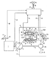
- the hydraulic pump 2 is a reversible, i.e. Pump delivering in two conveying directions with an adjustable, speed-dependent delivery volume, which is in fluid communication with the hydraulic motor via two working lines 5, 6; otherwise, the hydrostatic transmission is of a known design and is therefore not further described.
- the arrangement according to the invention for adjusting the delivery volume of the hydraulic pump 2 comprises a so-called hydraulic DA (for speed-dependent) device 7 for generating a control fluid with a control pressure proportional to the speed of the drive motor 1, an actuating device 8 which is connected to the actuator 9 of the hydraulic pump 2 Adjusting the delivery volume is coupled, a control valve 10 for controlling the supply of the control fluid to the actuating device 8, an electrically controllable actuating device 11 for the control valve 10, a feedback device 12 which detects the delivery volume setting of the hydraulic pump 2 and reports back to the control valve 10, and an electronic control unit 13 for outputting control signals to the actuating device 11.
- a so-called hydraulic DA (for speed-dependent) device 7 for generating a control fluid with a control pressure proportional to the speed of the drive motor 1
- an actuating device 8 which is connected to the actuator 9 of the hydraulic pump 2 Adjusting the delivery volume is coupled
- a control valve 10 for controlling the supply of the control fluid to the actuating device 8
- the DA device 7 enables so-called automotive driving, in which the delivery volume of the hydraulic pump 2 is proportional to the speed of the drive motor 1 is adjusted.
- the DA device 7 comprises an auxiliary pump 15 of constant delivery volume mechanically coupled to the hydraulic pump 2 via a through shaft 14 and with a delivery direction, as well as a control valve 16, usually referred to as a DA control valve, with a measuring orifice 17 shown here outside it.
- the DA control valve 16 opens, so that at its outlet and in a control pressure medium line 23 connected to it, the speed-proportional control pressure builds up, which counteracts the pressure difference at the measuring orifice 17 and the DA control valve 16 adjusted in the direction of the closed position until there is a force balance on its valve body.
- the signal pressure counteracting the pressure difference at the orifice 17 is directly proportional to the speed-proportional volume flow conveyed by the auxiliary pump 15 and thus to the speed of the drive motor 1.
- the control valve 10 is arranged in the control fluid line 23 and divides it into a main line section 31 leading to the DA control valve 16 and two branch line sections 32, 33, which lead to the control rooms 26, 27 of the actuating cylinder 8.
- the control valve 10 is a continuously adjustable 4/3-way valve, which in a known manner comprises a valve piston 34 and a valve sleeve 35 and each has a working connection T to a discharge line 36 leading to the tank 19, a working connection P to the main line section 31 of the control fluid line 23 and each has a working connection A, B to the branch line sections 32, 33.
- the control valve 10 is held by two valve centering springs 37, 38 in the (spring-centered) central position shown in the figure, in which all connections A, B, P and T are blocked and the hydraulic pump 2 is set to zero delivery volume.
- the control valve 10 is assigned a travel direction switch 39 which can be set to idle L, forward travel V and reverse travel R and a potentiometer 40 for detecting the respective position of the switch 39.
- the electronic control unit 13 is connected to the potentiometer 40 of the travel direction switch 39, via a signal line 45 to the sensor 30 for detecting the travel of the actuating piston 24 and to a first sensor 46 for detecting the setpoint speed of the drive motor 1 predetermined with the accelerator pedal 4 and a second sensor 47 for detecting the actual speed of the drive motor 1 each connected via a signal line 48, 49.
- control fluid loaded with the speed-proportional control pressure flows into the right pressure chamber 26 or left pressure chamber 27 of the actuating cylinder 8 and moves the actuating piston 24 in the direction of its left or right end position until the balance between the force of the respectively compressed centering spring 29 or 28 and the self-restoring force of the hydraulic pump 2 on the one hand and the hydraulic force of the signal pressure on the other hand.
- the end positions of the actuating piston 24 correspond to the maximum delivery volume of the hydraulic pump 2 in the respective flow direction.
- the setting of the control piston 24 begins in the direction of the middle position as soon as the above-mentioned speed and control pressure values are below the corresponding maximum values.
- the electronic control unit 13 detects the respective position of the actuating piston 24 via the output signal of the sensor 30 and amplifies the first control signal when the actuating piston 24 moves in the direction of its respective end position in proportion to the distance traveled by it and weakens it when the actuating piston moves in the direction of it Middle position also proportional to the travel.
- valve sleeve 35 via the return lever 12
- valve piston 34 via changes in the first control signal
- the feedback device 12 is ineffective, so that the control piston 24 is adjusted only by the speed-proportional signal pressure and thus the delivery volume of the hydraulic pump 2 as a function of the speed of the drive motor 1 along the predetermined signal pressure / speed characteristic.
- the actuating piston 24 of the Actuating cylinder 8 is moved to the right in the direction of its central position until the valve sleeve 35 following this movement via the return lever 12 reaches the position corresponding to the central position of the control valve 10, ie the control valve 10 closes.
- the actuating piston 24 is dependent on the volume of the actuating pressure medium flowing out of the right or left pressure chamber 26 or 27, which is proportional to the strength of the control signal and thus the speed depression of the drive motor 1, in the direction of its central position and thus the hydraulic pump 2 to the corresponding smaller delivery volume adjusted.
- the latter absorbs a lower torque corresponding to the smaller delivery volume, as a result of which the overload of the drive motor 1 is eliminated and the drop in speed is prevented.
- the hydraulic pump can - depending on the control of the control valve 10 with the second control signal - independently of the speed of the drive motor not only along any desired characteristic curve, for example, essentially perpendicular to the speed depression coordinate axis, but also up to each desired delivery volume are pivoted back, in which the torque absorbed by it is, for example, less than the drive torque of the drive motor.
- the power released in this way can, for example, be taken up by an additional consumer without a speed drop occurring beforehand.
- the device according to the invention thus enables both the conventional limit load control (pivoting back of the hydraulic pump to a delivery volume in which the torque it absorbs is equal to the torque output by the drive motor) and also a control going beyond this.
- Both controls can be carried out over the entire speed range of the drive motor. This is particularly advantageous when driving in the lower speed range before the drive motor develops its maximum torque.
- the hydraulic limit load control known from the prior art would under Using the DA device, a torque balance between the hydraulic pump and the drive motor can only be achieved with very high pressure, if at all, since the torque of the drive motor decreases with increasing speed drop in the lower speed range mentioned.
- the above mechanical feedback device is described here for the sake of simplicity in connection with the electronic control unit, but is mainly intended for use without it.
Landscapes
- Engineering & Computer Science (AREA)
- General Engineering & Computer Science (AREA)
- Mechanical Engineering (AREA)
- Physics & Mathematics (AREA)
- Fluid Mechanics (AREA)
- Computer Hardware Design (AREA)
- Control Of Positive-Displacement Pumps (AREA)
- Fluid-Pressure Circuits (AREA)
Applications Claiming Priority (2)
| Application Number | Priority Date | Filing Date | Title |
|---|---|---|---|
| DE19513032A DE19513032C1 (de) | 1995-04-06 | 1995-04-06 | Vorrichtung zum Verstellen des Fördervolumens einer Hydropumpe |
| DE19513032 | 1995-04-06 |
Publications (2)
| Publication Number | Publication Date |
|---|---|
| EP0736708A1 true EP0736708A1 (fr) | 1996-10-09 |
| EP0736708B1 EP0736708B1 (fr) | 1998-11-04 |
Family
ID=7759021
Family Applications (1)
| Application Number | Title | Priority Date | Filing Date |
|---|---|---|---|
| EP96104071A Expired - Lifetime EP0736708B1 (fr) | 1995-04-06 | 1996-03-14 | Dispositif d'ajustement du débit d'une pompe hydraulique |
Country Status (2)
| Country | Link |
|---|---|
| EP (1) | EP0736708B1 (fr) |
| DE (2) | DE19513032C1 (fr) |
Cited By (7)
| Publication number | Priority date | Publication date | Assignee | Title |
|---|---|---|---|---|
| US6478714B2 (en) | 2000-08-24 | 2002-11-12 | Daimlerchrysler A.G. | Device for controlling an internal combustion engine driving a utility unit |
| RU2264572C1 (ru) * | 2004-04-02 | 2005-11-20 | Открытое акционерное общество "Инновационная фирма "НАМИ-СЕРВИС" | Система управления гидрообъемной трансмиссией многоколесной транспортной машины |
| RU2264571C1 (ru) * | 2004-04-02 | 2005-11-20 | Открытое акционерное общество "Инновационная фирма "НАМИ-СЕРВИС" | Устройство управления гидрообъемной трансмиссией колесной машины |
| EP1930594A1 (fr) * | 2006-11-27 | 2008-06-11 | Robert Bosch GmbH | Procédé de régulation d'une pompe hydraulique et unité de commande électronique |
| US8958959B2 (en) | 2011-10-19 | 2015-02-17 | Wirtgen Gmbh | Self-propelling construction machine |
| CN109139409A (zh) * | 2018-09-30 | 2019-01-04 | 杭州力龙液压有限公司 | 数字式恒流量斜轴柱塞泵 |
| CN114562453A (zh) * | 2022-02-09 | 2022-05-31 | 三一汽车制造有限公司 | 一种工程车辆及其泵送作业的控制方法、装置 |
Families Citing this family (8)
| Publication number | Priority date | Publication date | Assignee | Title |
|---|---|---|---|---|
| EP1225281B1 (fr) * | 2001-01-23 | 2008-01-16 | Brueninghaus Hydromatik Gmbh | Commande hydraulique, notamment pour commander le mécanisme rotatif d'une excavatrice |
| DE10131853A1 (de) * | 2001-06-30 | 2003-01-23 | Wabco Gmbh & Co Ohg | Verfahren zur Ermittlung des Betätigungsdrucks eines druckmittelbetätigten Stellzylinders |
| DE102006018313A1 (de) | 2006-04-20 | 2007-10-25 | Zf Friedrichshafen Ag | Verfahren zur Bestimmung der Position eines Schaltelementes |
| DE102006018314A1 (de) * | 2006-04-20 | 2007-10-25 | Zf Friedrichshafen Ag | Verfahren zur Bestimmung eines Betätigungsdruckes eines Betätigungsmittels |
| DE102008002384B4 (de) | 2008-06-12 | 2015-07-16 | Zf Friedrichshafen Ag | Verfahren zur Grenzlastregelung eines hydrostatischen Antriebes |
| DE102011121520A1 (de) | 2011-12-16 | 2013-06-20 | Robert Bosch Gmbh | Verstelleinrichtung für eine Axialkolbenmaschine undAxialkolbenmaschine mit einer Verstelleinrichtung |
| DE102014109205B4 (de) | 2013-12-18 | 2023-09-21 | Linde Hydraulics Gmbh & Co. Kg | Hydrostatische Pumpe eines bedarfsstromgeregelten hydrostatischen Antriebssystems |
| DE102020215820A1 (de) * | 2020-12-14 | 2022-06-15 | Robert Bosch Gesellschaft mit beschränkter Haftung | Hydropumpe für einen hydrostatischen Antrieb, und hydrostatischer Antrieb |
Citations (7)
| Publication number | Priority date | Publication date | Assignee | Title |
|---|---|---|---|---|
| DE3400885A1 (de) * | 1984-01-12 | 1985-07-25 | Robert Bosch Gmbh, 7000 Stuttgart | Hydrostatischer antrieb |
| JPS61207229A (ja) * | 1985-03-12 | 1986-09-13 | Honda Motor Co Ltd | 車両用油圧式変速機のクラツチ装置 |
| DE3842291A1 (de) * | 1987-12-15 | 1989-07-27 | Kubota Ltd | Fahrsteuereinrichtung fuer ein arbeitsfahrzeug |
| EP0325679A1 (fr) * | 1988-01-14 | 1989-08-02 | Hydromatik GmbH | Transmission pour voitures automobiles |
| DE3903189A1 (de) * | 1989-02-03 | 1990-08-09 | Linde Ag | Verfahren zum steuern eines an eine antriebsmaschine angeschlossenen hydrostatischen getriebes und steuervorrichtung dafuer |
| EP0505688A1 (fr) * | 1991-03-26 | 1992-09-30 | CLAAS Kommanditgesellschaft auf Aktien | Commande de machine à déplacement positif d'une transmission hydrostatique-mécanique manoeuvrable sous charge |
| WO1994029619A1 (fr) * | 1993-06-09 | 1994-12-22 | Brueninghaus Hydromatik Gmbh | Systeme de transport hydrostatique |
Family Cites Families (1)
| Publication number | Priority date | Publication date | Assignee | Title |
|---|---|---|---|---|
| DE3807599A1 (de) * | 1988-03-08 | 1989-09-28 | Hydromatik Gmbh | Automotive antriebseinrichtung fuer maschinen und fahrzeuge |
-
1995
- 1995-04-06 DE DE19513032A patent/DE19513032C1/de not_active Expired - Fee Related
-
1996
- 1996-03-14 EP EP96104071A patent/EP0736708B1/fr not_active Expired - Lifetime
- 1996-03-14 DE DE59600758T patent/DE59600758D1/de not_active Expired - Fee Related
Patent Citations (7)
| Publication number | Priority date | Publication date | Assignee | Title |
|---|---|---|---|---|
| DE3400885A1 (de) * | 1984-01-12 | 1985-07-25 | Robert Bosch Gmbh, 7000 Stuttgart | Hydrostatischer antrieb |
| JPS61207229A (ja) * | 1985-03-12 | 1986-09-13 | Honda Motor Co Ltd | 車両用油圧式変速機のクラツチ装置 |
| DE3842291A1 (de) * | 1987-12-15 | 1989-07-27 | Kubota Ltd | Fahrsteuereinrichtung fuer ein arbeitsfahrzeug |
| EP0325679A1 (fr) * | 1988-01-14 | 1989-08-02 | Hydromatik GmbH | Transmission pour voitures automobiles |
| DE3903189A1 (de) * | 1989-02-03 | 1990-08-09 | Linde Ag | Verfahren zum steuern eines an eine antriebsmaschine angeschlossenen hydrostatischen getriebes und steuervorrichtung dafuer |
| EP0505688A1 (fr) * | 1991-03-26 | 1992-09-30 | CLAAS Kommanditgesellschaft auf Aktien | Commande de machine à déplacement positif d'une transmission hydrostatique-mécanique manoeuvrable sous charge |
| WO1994029619A1 (fr) * | 1993-06-09 | 1994-12-22 | Brueninghaus Hydromatik Gmbh | Systeme de transport hydrostatique |
Non-Patent Citations (1)
| Title |
|---|
| PATENT ABSTRACTS OF JAPAN vol. 011, no. 044 (M - 560) 10 February 1987 (1987-02-10) * |
Cited By (8)
| Publication number | Priority date | Publication date | Assignee | Title |
|---|---|---|---|---|
| US6478714B2 (en) | 2000-08-24 | 2002-11-12 | Daimlerchrysler A.G. | Device for controlling an internal combustion engine driving a utility unit |
| RU2264572C1 (ru) * | 2004-04-02 | 2005-11-20 | Открытое акционерное общество "Инновационная фирма "НАМИ-СЕРВИС" | Система управления гидрообъемной трансмиссией многоколесной транспортной машины |
| RU2264571C1 (ru) * | 2004-04-02 | 2005-11-20 | Открытое акционерное общество "Инновационная фирма "НАМИ-СЕРВИС" | Устройство управления гидрообъемной трансмиссией колесной машины |
| EP1930594A1 (fr) * | 2006-11-27 | 2008-06-11 | Robert Bosch GmbH | Procédé de régulation d'une pompe hydraulique et unité de commande électronique |
| US8958959B2 (en) | 2011-10-19 | 2015-02-17 | Wirtgen Gmbh | Self-propelling construction machine |
| CN109139409A (zh) * | 2018-09-30 | 2019-01-04 | 杭州力龙液压有限公司 | 数字式恒流量斜轴柱塞泵 |
| CN114562453A (zh) * | 2022-02-09 | 2022-05-31 | 三一汽车制造有限公司 | 一种工程车辆及其泵送作业的控制方法、装置 |
| CN114562453B (zh) * | 2022-02-09 | 2024-01-30 | 三一汽车制造有限公司 | 一种工程车辆及其泵送作业的控制方法、装置 |
Also Published As
| Publication number | Publication date |
|---|---|
| DE19513032C1 (de) | 1996-08-14 |
| DE59600758D1 (de) | 1998-12-10 |
| EP0736708B1 (fr) | 1998-11-04 |
Similar Documents
| Publication | Publication Date | Title |
|---|---|---|
| EP2179176B1 (fr) | Système hydraulique avec une machine hydrostatique réglable | |
| DE2522719C2 (de) | Steuereinrichtung | |
| DE19513032C1 (de) | Vorrichtung zum Verstellen des Fördervolumens einer Hydropumpe | |
| DE2700803C2 (de) | Regelungssystem für eine Antriebseinrichtung | |
| EP1588077B1 (fr) | Dispositif de reglage d'une transmission hydrostatique | |
| DE2813486C2 (de) | Steuervorrichtung für Hydraulikpumpen | |
| EP0615588B1 (fr) | Transmission hydrostatique | |
| EP0423704B1 (fr) | Dispositif de commande de la capacité de moteurs hydrauliques commandé par pression compensée pour la vitesse | |
| DE102004062388B4 (de) | Hydrostatischer Antrieb mit Drehzahlbegrenzung | |
| EP0701671B1 (fr) | Systeme de transport hydrostatique | |
| EP0273214A2 (fr) | Dispositif de réglage pour une machine hydrostatique | |
| EP0745189B1 (fr) | Dispositif de regulation du debit total d'au moins deux pompes hydrostatiques a cylindree variable | |
| DE4234139C2 (de) | Steuervorrichtung eines hydrostatischen Getriebes mit Bremsventil | |
| DE19542427A1 (de) | Hydrostatisches Antriebssystem für ein hydrostatisches betriebenes Fahrzeug | |
| EP1828643B1 (fr) | Procede pour freiner un vehicule entraine au moyen d'une boite de vitesses hydrostatique et boite de vitesses hydrostatique | |
| DE4407282C2 (de) | Hydrostatischer Antrieb | |
| EP0561153B1 (fr) | Dispositif de réglage de puissance pour au moins deux pompes hydrostatiques à débit variable | |
| DE19850162C1 (de) | Hydrostatisches Getriebe | |
| DE102006003517A1 (de) | Hydraulische Steuereinrichtung und Verfahren zur Ansteuerung zweier Aktuatoren | |
| DE3781522T2 (de) | Hydraulisches antriebsystem. | |
| EP0715698B1 (fr) | Transmission hydrostatique pourvue d'une soupape de frein | |
| DE60028796T2 (de) | Steuereinrichtung für ein stufenloses Getriebe | |
| DE10259315B3 (de) | Regelvorrichtung für einen Hydromotor | |
| EP0897062B1 (fr) | Circuit de contrôle de pression pour plusieurs pompes hydrauliques avec un transmetteur de pression moyenne | |
| DE19935007B4 (de) | Steuereinrichtung für eine hydraulische Maschine |
Legal Events
| Date | Code | Title | Description |
|---|---|---|---|
| PUAI | Public reference made under article 153(3) epc to a published international application that has entered the european phase |
Free format text: ORIGINAL CODE: 0009012 |
|
| AK | Designated contracting states |
Kind code of ref document: A1 Designated state(s): DE FR GB IT SE |
|
| 17P | Request for examination filed |
Effective date: 19961203 |
|
| GRAG | Despatch of communication of intention to grant |
Free format text: ORIGINAL CODE: EPIDOS AGRA |
|
| GRAG | Despatch of communication of intention to grant |
Free format text: ORIGINAL CODE: EPIDOS AGRA |
|
| GRAH | Despatch of communication of intention to grant a patent |
Free format text: ORIGINAL CODE: EPIDOS IGRA |
|
| 17Q | First examination report despatched |
Effective date: 19980318 |
|
| GRAH | Despatch of communication of intention to grant a patent |
Free format text: ORIGINAL CODE: EPIDOS IGRA |
|
| GRAA | (expected) grant |
Free format text: ORIGINAL CODE: 0009210 |
|
| AK | Designated contracting states |
Kind code of ref document: B1 Designated state(s): DE FR GB IT SE |
|
| GBT | Gb: translation of ep patent filed (gb section 77(6)(a)/1977) |
Effective date: 19981104 |
|
| REF | Corresponds to: |
Ref document number: 59600758 Country of ref document: DE Date of ref document: 19981210 |
|
| ET | Fr: translation filed | ||
| PLBE | No opposition filed within time limit |
Free format text: ORIGINAL CODE: 0009261 |
|
| STAA | Information on the status of an ep patent application or granted ep patent |
Free format text: STATUS: NO OPPOSITION FILED WITHIN TIME LIMIT |
|
| 26N | No opposition filed | ||
| REG | Reference to a national code |
Ref country code: GB Ref legal event code: IF02 |
|
| PGFP | Annual fee paid to national office [announced via postgrant information from national office to epo] |
Ref country code: SE Payment date: 20080313 Year of fee payment: 13 Ref country code: GB Payment date: 20080320 Year of fee payment: 13 |
|
| PGFP | Annual fee paid to national office [announced via postgrant information from national office to epo] |
Ref country code: FR Payment date: 20080314 Year of fee payment: 13 Ref country code: DE Payment date: 20080321 Year of fee payment: 13 |
|
| PGFP | Annual fee paid to national office [announced via postgrant information from national office to epo] |
Ref country code: IT Payment date: 20080328 Year of fee payment: 13 |
|
| EUG | Se: european patent has lapsed | ||
| GBPC | Gb: european patent ceased through non-payment of renewal fee |
Effective date: 20090314 |
|
| REG | Reference to a national code |
Ref country code: FR Ref legal event code: ST Effective date: 20091130 |
|
| PG25 | Lapsed in a contracting state [announced via postgrant information from national office to epo] |
Ref country code: DE Free format text: LAPSE BECAUSE OF NON-PAYMENT OF DUE FEES Effective date: 20091001 |
|
| PG25 | Lapsed in a contracting state [announced via postgrant information from national office to epo] |
Ref country code: GB Free format text: LAPSE BECAUSE OF NON-PAYMENT OF DUE FEES Effective date: 20090314 Ref country code: FR Free format text: LAPSE BECAUSE OF NON-PAYMENT OF DUE FEES Effective date: 20091123 |
|
| PG25 | Lapsed in a contracting state [announced via postgrant information from national office to epo] |
Ref country code: IT Free format text: LAPSE BECAUSE OF NON-PAYMENT OF DUE FEES Effective date: 20090314 |
|
| PG25 | Lapsed in a contracting state [announced via postgrant information from national office to epo] |
Ref country code: SE Free format text: LAPSE BECAUSE OF NON-PAYMENT OF DUE FEES Effective date: 20090315 |