EP0736761A2 - Surveillance pour système de diagnostic de moteur - Google Patents
Surveillance pour système de diagnostic de moteur Download PDFInfo
- Publication number
- EP0736761A2 EP0736761A2 EP96302359A EP96302359A EP0736761A2 EP 0736761 A2 EP0736761 A2 EP 0736761A2 EP 96302359 A EP96302359 A EP 96302359A EP 96302359 A EP96302359 A EP 96302359A EP 0736761 A2 EP0736761 A2 EP 0736761A2
- Authority
- EP
- European Patent Office
- Prior art keywords
- engine
- correction factor
- value
- correction
- operating point
- Prior art date
- Legal status (The legal status is an assumption and is not a legal conclusion. Google has not performed a legal analysis and makes no representation as to the accuracy of the status listed.)
- Withdrawn
Links
Images




Classifications
-
- G—PHYSICS
- G01—MEASURING; TESTING
- G01M—TESTING STATIC OR DYNAMIC BALANCE OF MACHINES OR STRUCTURES; TESTING OF STRUCTURES OR APPARATUS, NOT OTHERWISE PROVIDED FOR
- G01M15/00—Testing of engines
- G01M15/04—Testing internal-combustion engines
- G01M15/11—Testing internal-combustion engines by detecting misfire
-
- G—PHYSICS
- G01—MEASURING; TESTING
- G01P—MEASURING LINEAR OR ANGULAR SPEED, ACCELERATION, DECELERATION, OR SHOCK; INDICATING PRESENCE, ABSENCE, OR DIRECTION, OF MOVEMENT
- G01P21/00—Testing or calibrating of apparatus or devices covered by the preceding groups
- G01P21/02—Testing or calibrating of apparatus or devices covered by the preceding groups of speedometers
Definitions
- the present invention relates generally to on-board diagnostic monitors for internal combustion engines such as misfire detectors, and more specifically to on-board adjustment of correction factors used by the diagnostic monitor.
- One way to detect misfires in internal combustion engines is to measure crankshaft speed and observe fluctuations in speed. Detection of deviations in crankshaft velocities (as manifested by abnormal acceleration values) from expected normal crankshaft velocities is an indication of misfire. Deviations in acceleration are determined over nominally equal successive intervals of crankshaft rotation, referred to as “Profile-Ignition-Pick-Up intervals" (PIP intervals).
- PIP intervals is a digital signal received from a sensor, which detects specified positions of rotation of a crankshaft mounted wheel during engine rotation. PIP intervals are also known as combustion intervals, which are equal in length (but not necessarily phase) to the angular rotation between top dead centres of adjacent cylinders in the firing order.
- an engine will produce a series of PIP transition signals whose periods are inversely related to the average crankshaft velocity during a substantial portion of the power stroke for each of the cylinders in the engine.
- the crankshaft velocity will either remain constant (zero acceleration), increase (positive acceleration) or decrease (negative acceleration) depending on whether the engine is operating at steady state, accelerating or decelerating, respectively. For example, if a normal engine is operating under steady-state operation (no acceleration), then acceleration values of near zero are expected over successive PIP intervals.
- misfire detectors typically look for individual cylinders yielding acceleration values different from the local norm of all cylinders, where the local norm depends upon the operating condition (i.e., steady state, acceleration, or deceleration, etc.).
- the problem is that individual cylinders in normal engines tend to yield values of velocity that differ slightly from the local norm of all cylinders in a systematic manner according to cylinder number. In a normally operating engine, this systematic variation will interfere with the misfire detection system's ability to detect abnormal behaviour due to misfire.
- Dosdall et al. prefer to employ defuelled coast down when sensing encoder errors. The reason is to avoid uneven acceleration due to firing events during data collection, since with no fuel, all cylinders are unpowered.
- Application of the process specified in Dosdall et al to coast down data yields a set of values which indicates the actual PIP-interval spacings of the wheel relative to the nominal values (i.e., assumed equal spacing).
- crankshaft-torsional-flexing can occur when the power is cut-off (as in the Dosdall et al. patent), because inertial torques produce uneven motions (acceleration).
- the effects of such torsional variations on the calculated acceleration values are most pronounced at higher engine speeds as manifested in typical engine data.
- U.S. patent 5,377,537 discloses a method for removing the effects of torsional oscillations by applying correction factors to velocity measurements and using the corrected velocities (or accelerations) for misfire detection.
- Correction factors for each of the n PIP intervals of an engine cycle are generated for each of a multitude of engine operating conditions.
- Each set of n generated correction factors is stored in a table (a "look-up table" located in a memory unit) and has a corresponding unique address location. This table is determined empirically in the calibration of the engine type by a test engine.
- the correction factors are generated while the test engine is rotated at a fixed steady state operating point with combustion, where the operating point is typically a particular speed and load.
- the table is loaded in memory units of production vehicles. During operation, measured operational parameters from the engine (e.g., a particular speed and load) are used as an address to retrieve correction factors stored in the look-up table.
- test engine characterises the expected torsional oscillations for a particular engine design reasonably well
- production engines of that same design may exhibit individual variation and may also experience changes as the engines wear with use. Therefore, the effectiveness of a predetermined look-up table may be reduced over time unless it is adjusted or adapted for the changes.
- the present invention provides on-board adjustment of correction factors used by an engine diagnostic monitor, wherein the adjustment is not subject to the disadvantages described above.
- a correction factor originally obtained from a test engine is dynamically modified on-board a production engine in response to the detection of a time when it is safe to perform the adaptation.
- the invention provides a method for detecting malfunctions in an internal combustion engine.
- An engine variable is measured.
- a selected diagnostic variable is determined in response to the measured variable and a correction factor, wherein the correction factor reduces the effects of a known source of error in determining the selected diagnostic variable.
- a diagnostic classification is produced in response to the selected diagnostic variable and a diagnostic threshold set in accordance with a first false alarm rate.
- a malfunction signal is generated in response to the diagnostic classification.
- a safe adaptation classification is produced in response to the selected diagnostic variable and an adaptation threshold set in accordance with a second false alarm rate higher than the first false alarm rate.
- the correction factor is adapted by assigning a new value to the correction factor that tends to modify the determination of the selected diagnostic variable toward a predetermined value when the safe adaptation classification corresponds to an absence of a malfunction.
- the present invention employs similar sensing apparatus as those used in U.S. Patent No. 5,117,681 to Dosdall et al., incorporated herein by reference. A brief overview of these sensing devices is provided below.
- Figure 1 illustrates an example position sensing and velocity measuring system employed by the present invention.
- the engine rotation position sensing system of Figure 1 includes a rotor 100 including vanes 101, 102, and 103 which rotate with a crankshaft 104 (a three-vane rotor from a 6-cylinder engine is shown in this example).
- the vanes 101-103 pass between a hall effect sensor 105 and a permanent magnet 106 to generate a profile ignition pulse (PIP) signal 107 as the crankshaft 104 rotates.
- Vanes 101-103 are typically arranged to generate a rising edge in the PIP signal 10° before top dead centre (in the preferred embodiment, falling edges 70° before and 50° after top dead centre for a six cylinder engine) of each respective cylinder.
- the rising edge in the PIP signal actually indicates the approach to top dead centre of two engine cylinders, one of which is approaching a power stroke and one of which is approaching an intake stroke since it takes two full crankshaft rotations to complete an engine cycle.
- a cylinder identification (CID) sensor 107 is connected to a camshaft 108 for identifying which of the two cylinders is actually on its power stroke. Since camshaft 108 rotates once for every two rotations of crankshaft 104, a CID signal is preferably generated having a rising edge corresponding to the power stroke of cylinder No. 1.
- a timer 120 receives the PIP signal and the CID signal and measures elapsed time between predetermined engine position locations as determined by the CID and PIP signals (preferably between falling edges of PIP).
- the elapsed time ⁇ T i for each velocity measuring interval is output from timer 120 to a velocity calculator 121 where the assumed angular spacing ⁇ 0 is divided by time ⁇ T i to provide the velocity value V i .
- timer 120 and velocity calculator 121 are parts of firm/software in a processor system ("Processor") 140. Timer 120 and velocity calculator may also be implemented as hardware.
- a memory device 122 is coupled to processor 140 via a bi-directional bus 123.
- FIG. 2 An alternative embodiment of position sensing apparatus is shown in Figure 2.
- a multi-toothed wheel 202 is mounted on an engine for rotation with the crankshaft.
- a plurality of teeth 204 are disposed along the periphery of wheel 202 at a predetermined angular spacing.
- a sensor 206 is disposed in a fixed location closely spaced to teeth 204 for sensing when each tooth passes sensor 206.
- a missing tooth location 208 is provided on wheel 202 to establish an absolute location reference, e.g., at 90° before top dead centre of cylinder No. 1.
- Sensor 206 is connected to timer 120 and velocity calculator 121 as described with reference to Figure 1. However, since the velocity measuring intervals in this embodiment are longer than the spacing of teeth 204, an interval former 210 is disposed between timer 120 and velocity calculator 121 in order to provide the sum of the measured time periods for the consecutive teeth which are included in the particular velocity interval to be measured. As shown in Figs. 1 and 2, timer 120, velocity calculator 121 and interval former 210 may preferably be implemented in the programmed processor 140.
- FIG. 3 is a flow chart illustrating the procedural steps used by processor 140 to obtain correction factors (C k ).
- step 302 the engine is rotated at a fixed steady state condition.
- “Steady state” means that the engine is rotated at a particular speed and load during powered operating conditions, where speed is in Revolutions-Per-Minute (RPM) and load is a percentage of full air charge, which is nominally proportional to torque.
- RPM Revolutions-Per-Minute
- load is a percentage of full air charge, which is nominally proportional to torque.
- the number of load and speed points selected for generating the look-up table is dependent upon accuracy required of the system and the engine being characterised.
- Speed and load are the two most important factors that effect torsional effects in the crankshaft 104.
- operational parameters other than speed and load e.g., spark advance and Exhaust Gas Recirculation (EGR), which are typically found to effect engine torque, and hence, the degree of torsional flexing of the crankshaft 104.
- EGR Exhaust Gas Recirculation
- a unique set of correction factors one for each cylinder, is determined for each unique steady state operating point (particular speed and load) from data collected over N complete cycles of a normally operating engine.
- C 1 is the correction factor at a given operating condition for cylinder 1
- C 2 is the corresponding factor for the next cylinder in firing order, and so forth.
- the correction factor for the k th cylinder is based on the average ratio of each PIP-interval velocity (denoted V i ) associated with cylinder k, to the average velocity (denoted W i ) over an entire engine cycle substantially centred on the PIP interval.
- This relationship is graphically depicted in Figure 4A, which represents two revolutions of a position encoder during one complete cycle 402 of an example six-cylinder engine (where a PIP interval is denoted 404).
- the six measurement intervals are designated i-3, i-2, i-1, i, i+ 1, i+2, where a single estimate of the correction factor for interval i is to be determined.
- the two velocities calculated for each i are the average velocity (V i ) over the PIP interval 404 (length 120°) and the average velocity (W i ) over the entire engine cycle 402 (length 720° or calculated over a plurality of engine cycles 402).
- each PIP interval 404 can be measured by its corresponding change in time ⁇ t i and each entire engine cycle 402 can be measured by its change in time denoted ⁇ s i .
- processor 140 stores correction factors obtained in step 304, in memory 122 as part of a "table of correction factors” also referred to as the "look-up table.”
- Memory 122 is preferably implemented using random-access memory (RAM), but may be any type of memory used with processors such as DRAM, SRAM, etc.
- step 308 an operational parameter (such as speed and/or load), which affects crankshaft torque, is modified to obtain additional correction factors.
- Steps 304, 306 and 308 are then repeated until the look-up table is complete, which is shown as the "YES" path of decisional step 310.
- the more correction factors that are generated and stored in memory 122 the more accurate will be the resulting system.
- the pattern of torsional fluctuation at each speed and load is mostly a function of the engine design, and can be characterised in a table of correction factors in memory 122 having calibrated correction values.
- the table of correction factors 122 is determined empirically in the calibration of the engine type by a test engine (or through simulation, if sufficiently sophisticated). Once the look-up table in memory 122 is complete, it can be implemented in production vehicles. This look-up table of memory 122 allows corrections factors C k to be determined for each engine operating condition. For instance, if the engine were operating at 2000 RPM at a load of 0.25, these two operating parameters would be used as an index (or address) (via bus 123 shown in Figs. 1 and 2) to the look-up table of memory 122 (the load input to bus 123 is not shown in Figs. 1 and 2).
- the output, via bus 123, of the look-up table would be the correction factors C k corresponding to the operating conditions of 2000 RPM at a load of 0.25. Interpolation can be used to estimate each of n correction factors from the nearest adjacent points in the look-up table of memory 122, if the operational parameters do not exactly match the indexed value in the look-up table of memory 122.
- FIG. 5 is a flow chart illustrating how the torsional correction factors are deployed in a production vehicle having an internal combustion engine.
- step 502 the engine is rotated at a particular speed and load according to driving conditions typically encountered by a production vehicle in day-to-day use.
- step 504 each new speed and load of the engine is measured as described above.
- step 506 the speed and load values are employed as an input to memory 122 via bus 123 to retrieve a corresponding correction factor(s) from memory 122. It is not necessary to retrieve new correction factors every PIP interval, however, the system is generally more accurate if the correction factors are updated in a timely fashion.
- V i is the uncorrected velocity for the ith interval
- B k is the wheel profile correction factor (as described in the Dosdall et al. patent)
- C k * is the current value of the torsional correction factor
- k is the cylinder number associated with the i th interval.
- Many alternative functions can be devised to obtain the corrected velocity.
- an alternative method of deriving the C k is to perform a least squares fit of the corrected PIP-interval velocities to the cycle-average velocities. In other words, choose the C k so as to minimize an error defined in equation (1.3) as:
- equation (1.0) is equivalent to a least squares fit of the relative velocity differences, with the error defined by equation 1.5:
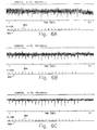
- Figs. 6A-6C show traces of Deviation Acceleration (DACCEL) determined from the PIP interval times of a six-cylinder engine operating at about 4000 rpm at light load.
- DACCEL is a fundamental detection parameter (sometimes referred to as "accel. deviation") (described in U.S.
- Figure 6A shows DACCEL calculated without any type of correction to V i .
- the regular occurrences of misfire induced throughout the data file are only marginally visible above the noise at this engine speed and load. Occurrences of misfire may be determined from the K-COIL signal 602 (shown below the DACCEL trace in Figs. 6A-6C), which records instances of intentional misfire creation (shown as a vertical spike 604).
- Figure 6B shows some improvement in the signal-to-noise ratio over the same points after applying wheel-profile correction factors to the velocities, as described in the Dosdall et al. patent. Correction for profile errors yields only a modest improvement in signal quality in this case, because the wheel on the engine used to generate this data was already fairly accurate. However, applying correction factors to compensate for torsional fluctuations as described above provides much greater improvement, resulting in the more distinguishable misfire signal as shown in Figure 6C according to the present invention.
- Tests at other speed and load points yield similar improvements, but with slightly different correction parameters on account of the differing torsional effects.
- a look-up table in memory 122 can be created to allow interpolation of the proper correction at each speed and load point, while the engine rotates.
- equation (2.1) shows that the D k values have a strong dependence on engine speed, through the term V i 2 , even if factors C k are independent of speed (as in the case of wheel profile correction). As a result, it is preferred to apply correction in the calculation of velocity instead of acceleration. However, either method will accomplish the task of correction for effects which diminish the signal quality of misfire detection by crankshaft speed fluctuations.
- the invention uses a set of base values for the correction factors that are derived from a test engine and adapts these values very slowly since it is only necessary to track changes resulting from ageing of the engine and not changes in speed, load, or other conditions of the engine during adaptation. Since adaptation can proceed very slowly, it is possible to be very selective in accepting data for interpolating new correction factor values. Therefore, adaptation is ceased whenever misfire or abnormal operation is even remotely suspected.
- the suspension of adaptation does not preclude selection or interpolation of new correction factor values from the table as engine speed and load change, thus retaining the ability to detect misfire under all conditions.
- the present invention further performs a classification of cylinder events according to whether a safe adaptation time exists or not.
- the method of determining these two classifications may be similar, they are different in at least the important respect that the method for determining the safe adaptation classification has a higher acceptable false alarm rate (i.e., is more likely to call an event as a misfire or other malfunction).
- the two groups of cylinder events i.e., normal and misfiring
- a threshold i.e., you cannot draw a horizontal line that completely separates the two groups.
- Setting the threshold to a level where it would detect nearly all occurrences of misfires would also yield to many false alarms (i.e., false declarations of misfire when a normal firing actually occurred).
- the false alarm rate of a misfire detector must be kept very low in order to avoid false indication of engine problems (such as illumination of a malfunction indicator light connected to processor 140 in Fig. 1).
- Figure 8 shows the results of torsional correction applied to the data of Figure 7. The improved quality of this signal permits reliable misfire detection.
- the present invention provides a method for classifying cylinder events according to a safe adaptation time wherein it is possible to distinguish between times of normal operation and times of malfunction or misfire.
- the method does not rely on use of the correction factors in making the safe adaptation classification, so that it is not possible to learn a malfunction as normal operation. Since it is possible to adapt the correction factor values at a very slow pace, the method need only identify some occasional periods of normal operation. Nevertheless, the determination of normalcy should be made with very high reliability.
- the method for determining a safe adaptation time must be highly reliable in detecting normalcy, it is acceptable to have a relatively high false alarm rate (thereby incorrectly calling some cylinder events as misfires) since more than adequate amounts of data will still be available to perform adaptation.
- a digital lowpass filter is applied to the acceleration values of Figure 7 thereby producing the filtered DACCEL data shown in Figure 9.
- the reduced bandwidth of the acceleration data provided by lowpass filtering reduces noise in the signal (whether from random events or synchronous events such as result from torsional fluctuations).
- the amplitude of the DACCEL signal is reduced by filtering and the difference between misfires and adjacent normal events is blurred, the difference between periods of engine operation with misfire present and periods of engine operation with no misfire is much more evident.
- it is a relatively straight forward task to set a DACCEL threshold that can easily identify periods when no misfire is occurring.
- a new value for the correction factor at the current operating point of the engine is derived using the unfiltered crankshaft data.
- the overall method of the preferred embodiment is shown in Figure 10.
- several engine operating variables such as PIP interval, RPM, and load are measured in step 702.
- a correction factor value is retrieved in step 703 according to the table indexes such as RPM and load.
- a diagnostic variable such as DACCEL is calculated in step 704.
- a diagnostic classification is determined in step 705.
- diagnostic classifications call each event as a misfire, no misfire, or no test (i.e., not able to distinguish a misfire) as described in the previously mentioned patents.
- step 706 a check is made to determine whether the diagnostic classification of step 705 represented a malfunction (e.g., a misfire). If yes, then the rate of malfunction or misfires is accumulated in step 707. Any corrective action or indication of a malfunction condition is performed as necessary if the accumulated rate of misfire exceeds a predetermined rate. Then, a return is made to step 702 to measure further variables.
- a malfunction e.g., a misfire
- step 706 determines that either no malfunction was present or a no test condition was present.
- a safe adaptation classification is determined in step 708.
- the filtered DACCEL data shown in Figure 9 is judged against a criterion such as comparison with a threshold that distinguishes between periods of engine operation that are normal and periods that possibly include misfire events.
- a check is made in step 709 to determine whether the safe adaptation classification represents a safe adaptation time. If not, a return is made to step 702 to measure further engine variables. If yes, then a new value of a correction factor is adapted in step 710.
- the actual new value is derived by determining the correction factor value that would modify the calculated diagnostic variable (DACCEL) to a predetermined value indicative of normalcy (e.g., zero). Using that result, the existing correction factor value is incrementally modified by a fraction of the difference.
- Lowpass filtering of DACCEL data can be obtained using an explicit filter, such as a digital filter, or an implicit filter, such as would be obtained by lengthening the velocity measurement intervals (e.g., combining several PIP intervals prior to calculating velocity). It should be noted that although filtered DACCEL data is used to determine a safe adaptation time in step 708, only unfiltered data is used in determining the actual correction in step 710 and in detecting misfires in steps 704 and 705.
- the preferred embodiment uses a combined correction factor table (i.e., where the original correction factor values stored in a particular vehicle embody the torsional correction factors from the test engine multiplied by the wheel profile correction factors for the individual engine in the particular vehicle), it is not necessary to explicitly account for wheel profile correction in the adaptation. In other embodiments where wheel profile correction factors are maintained and applied to the velocity data separately, it is necessary to remove them from the newly adapted correction factor values prior to adjusting the values stored in the torsional correction table.
- Figure 11 shows a portion of a table of correction factors indexed by speed (RPM) and load (percent air charge of maximum). Correction factors are provided at the reference operating points that are directly indexed by the speed and load values in the table. Correction factor values for points intermediate the indexed values are interpolated during correction for misfire detection. Each correction factor value in the table is denoted C.
- the four nearest points in the table surrounding a current measured operating point (x,y) are designated (x 0 , y 0 ), (x 1 , y 0 ), (x 0 , y 1 ) and (x 1 , y 1 ) and the corresponding correction factor values are designated C 00 , C 10 , C 01 and C 11 , respectively.
- the preferred embodiment modifies the four neighbouring table values accordingly.
- ⁇ may be calibrated to any value between 0 and 1, it is typically very small (i.e., much less than 1), corresponding to a very slow rate of adaptation.
- Each of the above equations represents an exponentially weighted moving average of the incoming data with a very long time constant.
- the amount of computation can be reduced by adjusting only the single closest reference point in the table to the newly incoming data.
Landscapes
- Physics & Mathematics (AREA)
- General Physics & Mathematics (AREA)
- Chemical & Material Sciences (AREA)
- Engineering & Computer Science (AREA)
- Combustion & Propulsion (AREA)
- Combined Controls Of Internal Combustion Engines (AREA)
- Testing Of Engines (AREA)
- Ignition Installations For Internal Combustion Engines (AREA)
Applications Claiming Priority (2)
| Application Number | Priority Date | Filing Date | Title |
|---|---|---|---|
| US08/417,356 US5528931A (en) | 1995-04-05 | 1995-04-05 | Engine diagnostic monitor with on-board adjustment of correction factors |
| US417356 | 2003-04-16 |
Publications (2)
| Publication Number | Publication Date |
|---|---|
| EP0736761A2 true EP0736761A2 (fr) | 1996-10-09 |
| EP0736761A3 EP0736761A3 (fr) | 1998-01-21 |
Family
ID=23653665
Family Applications (1)
| Application Number | Title | Priority Date | Filing Date |
|---|---|---|---|
| EP96302359A Withdrawn EP0736761A3 (fr) | 1995-04-05 | 1996-04-03 | Surveillance pour système de diagnostic de moteur |
Country Status (3)
| Country | Link |
|---|---|
| US (1) | US5528931A (fr) |
| EP (1) | EP0736761A3 (fr) |
| JP (1) | JPH08284740A (fr) |
Families Citing this family (20)
| Publication number | Priority date | Publication date | Assignee | Title |
|---|---|---|---|---|
| DE4406606A1 (de) * | 1994-03-01 | 1995-09-07 | Audi Ag | Adaptionsvorrichtung für ein Geberrad an einem Verbrennungsmotor |
| JP3120268B2 (ja) * | 1995-03-22 | 2000-12-25 | 株式会社ユニシアジェックス | 多気筒内燃機関の失火診断装置 |
| US5806014A (en) * | 1995-05-01 | 1998-09-08 | Motorola Inc. | Combustion control of an internal combustion engine proximate an extinction limit |
| US5703283A (en) * | 1995-11-24 | 1997-12-30 | Motorola Inc. | Detrending engine positional data for rotating position encoders |
| JP3986603B2 (ja) * | 1996-02-02 | 2007-10-03 | ロベルト・ボッシュ・ゲゼルシャフト・ミト・ベシュレンクテル・ハフツング | 燃焼ミスファイヤの検出方法 |
| US5794171A (en) * | 1996-02-29 | 1998-08-11 | Ford Global Technologies, Inc. | Process for deriving predictive model of crankshaft rotation of a combustion engine |
| US6199007B1 (en) * | 1996-07-09 | 2001-03-06 | Caterpillar Inc. | Method and system for determining an absolute power loss condition in an internal combustion engine |
| JP3449170B2 (ja) * | 1996-08-09 | 2003-09-22 | トヨタ自動車株式会社 | 内燃機関の失火検出装置 |
| FR2768179B1 (fr) * | 1997-09-05 | 1999-10-15 | Renault | Procede de detection d'une perturbation anormale du couple d'un moteur a combustion interne |
| US6223120B1 (en) | 1998-11-19 | 2001-04-24 | Jeremy Williams | Cylinder torque estimation using crankshaft angular response measurements |
| DE19858536A1 (de) * | 1998-12-18 | 2000-06-21 | Bosch Gmbh Robert | Verfahren zur Signalauswertung |
| US6216678B1 (en) * | 2000-01-19 | 2001-04-17 | Ford Global Technologies, Inc. | Method and apparatus for generating and identifying misfires |
| DE10017107A1 (de) * | 2000-04-06 | 2001-10-18 | Bosch Gmbh Robert | Verfahren zur Kompensation der Drehunförmigkeit bei der Drehzahlerfassung |
| US6847882B2 (en) * | 2003-05-15 | 2005-01-25 | Visteon Global Technologies, Inc. | Misfire detection system and method of median filtering |
| WO2005028964A2 (fr) * | 2003-09-17 | 2005-03-31 | Hvac-Sales, Inc. | Patte de fixation universelle et procede pour transporter un conduit assemble |
| US7167793B1 (en) | 2005-08-18 | 2007-01-23 | Ford Global Technologies, Llc | Engine position correction |
| JP4279866B2 (ja) * | 2006-10-30 | 2009-06-17 | 本田技研工業株式会社 | 内燃機関の失火検出装置 |
| JP4339347B2 (ja) * | 2006-10-30 | 2009-10-07 | 本田技研工業株式会社 | 内燃機関のクランク角速度検出装置 |
| US7991585B2 (en) | 2008-10-01 | 2011-08-02 | Toyota Motor Engineering & Manufacturing North America, Inc. | Method and apparatus for three dimensional calibration of an on-board diagnostics system |
| US8301324B2 (en) * | 2011-01-11 | 2012-10-30 | GM Global Technology Operations LLC | Wobble compensation of an encoder speed signal for an electric motor |
Family Cites Families (19)
| Publication number | Priority date | Publication date | Assignee | Title |
|---|---|---|---|---|
| US5041979A (en) * | 1987-04-08 | 1991-08-20 | Motorola, Inc. | Bounded synchronous angle counter |
| JPH07122418B2 (ja) * | 1990-04-02 | 1995-12-25 | トヨタ自動車株式会社 | 内燃機関の異常気筒検出装置 |
| JPH0472449A (ja) * | 1990-07-10 | 1992-03-06 | Fuji Heavy Ind Ltd | エンジンの失火診断装置 |
| US5044195A (en) * | 1990-08-24 | 1991-09-03 | Ford Motor Company | Misfire detection in an internal combustion engine |
| US5117681A (en) * | 1990-10-01 | 1992-06-02 | Ford Motor Company | Correction of systematic position-sensing errors in internal combustion engines |
| US5263453A (en) * | 1990-11-01 | 1993-11-23 | Nippondenso Co., Ltd. | Apparatus for detecting misfire in internal combustion engines for vehicles |
| US5394742A (en) * | 1990-12-03 | 1995-03-07 | Siemens Aktiengesellschaft | Method for recognizing abnormal combustions in the cylinder of an internal-combustion engine |
| US5269178A (en) * | 1990-12-10 | 1993-12-14 | Sensortech, L.P. | Engine misfire, knock of roughness detection method and apparatus |
| JP2564427B2 (ja) * | 1991-01-14 | 1996-12-18 | 三菱電機株式会社 | 内燃機関失火検出方法及び装置 |
| US5079945A (en) * | 1991-01-23 | 1992-01-14 | Delco Electronics Corporation | Crankshaft direction of rotation detecting apparatus |
| US5307671A (en) * | 1991-03-04 | 1994-05-03 | Mitsubishi Denki Kabushiki Kaisha | Method for detecting misfires in gasoline internal combustion engine |
| JP2982381B2 (ja) * | 1991-06-12 | 1999-11-22 | 株式会社デンソー | 内燃機関用失火検出装置 |
| JPH05195858A (ja) * | 1991-11-08 | 1993-08-03 | Nippondenso Co Ltd | 多気筒内燃機関の失火検出装置 |
| WO1993012332A1 (fr) * | 1991-12-19 | 1993-06-24 | Caterpillar Inc. | Procede de diagnostic de moteur a l'aide de modeles informatises |
| US5587909A (en) * | 1992-06-16 | 1996-12-24 | Mitsubishi Jidosha Kogyo Kabushiki Kaisha | Misfire detecting method |
| US5237862A (en) * | 1992-06-22 | 1993-08-24 | Ford Motor Company | Adaptive method of cylinder misfire detection in an internal combustion engine |
| US5361629A (en) * | 1992-08-21 | 1994-11-08 | Chrysler Corporation | Single sensor misfire detection apparatus and method for an internal combustion engine |
| JP2666231B2 (ja) * | 1992-09-11 | 1997-10-22 | 本田技研工業株式会社 | 内燃エンジンの燃焼状態検出装置 |
| US5377537A (en) * | 1993-09-01 | 1995-01-03 | Ford Motor Company | System and method to compensate for torsional disturbances in measured crankshaft velocities for engine misfire detection |
-
1995
- 1995-04-05 US US08/417,356 patent/US5528931A/en not_active Expired - Lifetime
-
1996
- 1996-04-03 EP EP96302359A patent/EP0736761A3/fr not_active Withdrawn
- 1996-04-04 JP JP8082701A patent/JPH08284740A/ja active Pending
Also Published As
| Publication number | Publication date |
|---|---|
| EP0736761A3 (fr) | 1998-01-21 |
| US5528931A (en) | 1996-06-25 |
| JPH08284740A (ja) | 1996-10-29 |
Similar Documents
| Publication | Publication Date | Title |
|---|---|---|
| US5528931A (en) | Engine diagnostic monitor with on-board adjustment of correction factors | |
| EP0646711B1 (fr) | Système et procédé pour compenser des pertubations de torsion dans des vilebrequins | |
| EP0736760B1 (fr) | Transformation non-linéaire et dynamique pour la correction d'un accélération de vilebrequin comportant des oscillations de torsion | |
| US5109695A (en) | Misfire detection in an internal combustion engine | |
| US6023651A (en) | Internal combustion engine misfire detection with engine acceleration and deceleration correction during a repetitive misfire condition | |
| US5095742A (en) | Determining crankshaft acceleration in an internal combustion engine | |
| US5044194A (en) | Misfire detection in an internal combustion engine | |
| US5044195A (en) | Misfire detection in an internal combustion engine | |
| US4715009A (en) | Device for determining angular position of a rotating part | |
| JP3995054B2 (ja) | 多シリンダ式内燃機関のミスファイアを検出する方法 | |
| US5732382A (en) | Method for identifying misfire events of an internal combustion engine | |
| US5794171A (en) | Process for deriving predictive model of crankshaft rotation of a combustion engine | |
| US5506778A (en) | Misfire detection method based on a change in crankshaft rotation | |
| EP0677165B1 (fr) | Systeme permettant de determiner un defaut d'allumage dans un moteur | |
| US5531108A (en) | Adaptive correction of torsional and wheel profile position irregularities for misfire detection | |
| JPH04219448A (ja) | 内燃機関における不点火検出装置 | |
| JP2666232B2 (ja) | 内燃エンジンの燃焼状態検出装置 | |
| EP0551764B1 (fr) | Méthode et dispositif pour la détection de ratées d'allumage et de route inégale | |
| EP0757239B1 (fr) | Détecteur de raté d'allumage pour moteur à combustion interne | |
| US6725709B2 (en) | Combustion state diagnosing system and combustion state diagnosing method for diagnosing engine and recording medium | |
| US5509302A (en) | Misfire detection in internal combustion engines | |
| US5390537A (en) | Combustion state-detecting system for internal combustion engines | |
| US6023964A (en) | Misfire diagnosis method and apparatus of internal combustion engine | |
| ES2270603T3 (es) | Metodo y sistema de deteccion de fallos por correccion sincronizada. | |
| JPH0693919A (ja) | 内燃エンジンの燃焼状態検出装置 |
Legal Events
| Date | Code | Title | Description |
|---|---|---|---|
| PUAI | Public reference made under article 153(3) epc to a published international application that has entered the european phase |
Free format text: ORIGINAL CODE: 0009012 |
|
| AK | Designated contracting states |
Kind code of ref document: A2 Designated state(s): DE FR GB |
|
| PUAL | Search report despatched |
Free format text: ORIGINAL CODE: 0009013 |
|
| AK | Designated contracting states |
Kind code of ref document: A3 Designated state(s): DE FR GB |
|
| 17P | Request for examination filed |
Effective date: 19980609 |
|
| 17Q | First examination report despatched |
Effective date: 20010406 |
|
| GRAG | Despatch of communication of intention to grant |
Free format text: ORIGINAL CODE: EPIDOS AGRA |
|
| GRAG | Despatch of communication of intention to grant |
Free format text: ORIGINAL CODE: EPIDOS AGRA |
|
| GRAH | Despatch of communication of intention to grant a patent |
Free format text: ORIGINAL CODE: EPIDOS IGRA |
|
| STAA | Information on the status of an ep patent application or granted ep patent |
Free format text: STATUS: THE APPLICATION IS DEEMED TO BE WITHDRAWN |
|
| 18D | Application deemed to be withdrawn |
Effective date: 20020518 |