EP0736775B1 - Circuit pour tester la connexion d'un dispositif de reproduction sonore aux sources de reproduction sonore - Google Patents
Circuit pour tester la connexion d'un dispositif de reproduction sonore aux sources de reproduction sonore Download PDFInfo
- Publication number
- EP0736775B1 EP0736775B1 EP96200860A EP96200860A EP0736775B1 EP 0736775 B1 EP0736775 B1 EP 0736775B1 EP 96200860 A EP96200860 A EP 96200860A EP 96200860 A EP96200860 A EP 96200860A EP 0736775 B1 EP0736775 B1 EP 0736775B1
- Authority
- EP
- European Patent Office
- Prior art keywords
- audio signal
- voltage
- audio
- source
- signal source
- Prior art date
- Legal status (The legal status is an assumption and is not a legal conclusion. Google has not performed a legal analysis and makes no representation as to the accuracy of the status listed.)
- Expired - Lifetime
Links
Images
Classifications
-
- G—PHYSICS
- G01—MEASURING; TESTING
- G01R—MEASURING ELECTRIC VARIABLES; MEASURING MAGNETIC VARIABLES
- G01R31/00—Arrangements for testing electric properties; Arrangements for locating electric faults; Arrangements for electrical testing characterised by what is being tested not provided for elsewhere
- G01R31/50—Testing of electric apparatus, lines, cables or components for short-circuits, continuity, leakage current or incorrect line connections
- G01R31/66—Testing of connections, e.g. of plugs or non-disconnectable joints
- G01R31/70—Testing of connections between components and printed circuit boards
-
- H—ELECTRICITY
- H04—ELECTRIC COMMUNICATION TECHNIQUE
- H04R—LOUDSPEAKERS, MICROPHONES, GRAMOPHONE PICK-UPS OR LIKE ACOUSTIC ELECTROMECHANICAL TRANSDUCERS; ELECTRIC HEARING AIDS; PUBLIC ADDRESS SYSTEMS
- H04R29/00—Monitoring arrangements; Testing arrangements
- H04R29/001—Monitoring arrangements; Testing arrangements for loudspeakers
Definitions
- the invention relates to a circuit arrangement for Check the connection of a sound player to one Sound source.
- the invention relates to such a circuit arrangement for use in a sound player in a vehicle, for example a car radio.
- test device for headphones is one Known head arrangement with which the impedance is checked can.
- the invention has the task of a circuit arrangement for Check the connection of a sound player to one To create sound signal source through which the examination of the nature this connection in easier and faster Way is possible.
- the invention enables a targeted error diagnosis of the connection of one Sound reproduction device to a sound signal source without additional test equipment.
- a Such fault diagnosis can be carried out in a very simple manner, for example without test devices can also be done by an inexperienced user. This user is This enables the device to quickly and precisely identify specific causes of errors check, without, for example, facilities and personnel to have to consult a specialist workshop. In addition, also in such Case simplifies troubleshooting for the specialist staff, resulting in an overall leads to a significant reduction in maintenance and repair costs.
- the invention takes advantage of the knowledge that the of the sound signal source from the power supply with current increasing sound signal power increases and at the impedance across which the supply voltage is supplied by the power supply to the sound signal source, causing an increasing tension.
- the current and the one caused by it However, there is no voltage if the sound reproduction device is not connected to the Sound signal source is connected. This can lead to interruptions in the connection can be easily detected between these two parts of the addressed devices.
- the impedance mentioned does not have to be separately in the connection of the Power supply to the audio signal source can be inserted. Rather, it is enough an existing smoothing circuit for the supply voltage or an at real power supplies always available, finite internal resistance.
- Circuit arrangement for a comparison measurement set up by the fluctuations the absolute values, for example those provided by the voltage supply Voltage can be eliminated. This makes it very fine and precise Detection of even small changes in the supply voltage is possible.
- the circuit arrangement according to the invention are the power setting device, the voltage measuring device and the comparison device as part of a control circuit for controlling the operation of the Sound signal source trained.
- this control can be digital Control can be carried out with a microprocessor. This will make the Circuitry for the invention kept within very narrow limits.
- the power setting device can also be configured in the control circuit existing volume control be formed, so that no additional circuitry arises.
- the test is carried out for example with an additional sequential control system in the microprocessor is involved. This allows the operational control for the intended Operation of the sound reproducing device and the sound signal source and the control form a common component for the test.
- a device for delivering the Error signal can be provided as an acoustic signal, in particular a buzzer arrangement includes.
- a buzzer arrangement or a comparable one Device for emitting an acoustic signal can be independent of the sound reproducing devices to be tested, i.e. even in the event that this are not connected incorrectly, a simple error signal is output.
- Another option for outputting the error signal is an optical one Display, for example on one for the display of operating parameters of the Sound signal source already present display device.
- this comprises a test sound source for Feeding a test oscillation into the audio signal source and is from the Sound signal source for measuring the supply voltage on on the test vibration based sound signal with a specifiable sound signal power to the Sound reproduction device can be emitted.
- the advantage of a defined basis for the implementation Check as current, unpredictable fluctuations from the Sound signal source of delivered signals can be excluded.
- a reduction in the amount of circuitry then carries on training in this way in that the test sound source from the device for emitting the error signal as acoustic signal is included. This enables the test sound source to be used on the one hand Generation of the test vibration and on the other hand to generate the error signal be exploited.
- the sound reproduction device comprises at least a speaker and is the measurement of the supply voltage for each speaker can be carried out separately. This is a targeted test for more extensive ones Sound reproduction devices, in particular stereo systems in motor vehicles, possible because these are often equipped with a plurality of speakers.
- the sequence control for checking the individual loudspeakers is advantageous coupled with balance and / or fader controls.
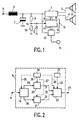
- the sound signal source 1 shows a sound signal source 1, to which two a sound reproduction device 2 forming speakers are connected. About this in the present example two speaker lines 3, 4 existing connection will sound signal power from the sound signal source 1 to the sound reproducing device 2.
- the sound signal source with energy from a voltage supply is the sound signal source 1 continues via an impedance 5 with a voltage supply connection 6 connected.
- Power supply shown are connected to the sound signal source 1 supplies a supply voltage.
- the impedance is 5 as a smoothing inductance executed, which usually have a certain ohmic resistance is.
- an internal resistance of the not shown Count the power supply. Also shown is a smoothing capacitor 7 from a connection facing away from the voltage supply connection 6 Impedance 5 is arranged to ground. Impedance 5 and smoothing capacitor 7 form a sieve or smoothing circle to suppress one as DC voltage formed supply voltage at the voltage supply connection 6 superimposed AC components.
- the audio signal source 1 During operation of the audio signal source 1, it takes one from the voltage supply Power, in part as sound signal power to the sound reproducing device is forwarded. As a result, a current flows from the voltage supply connection 6 through the impedance 5 in the sound signal source 1, which with increasing sound signal power increases. This current causes impedance 5 (and possibly in the internal resistance of the power supply, not shown) a voltage caused by the supply voltage at the audio signal source compared to the idle case, in which ideally none of the audio signal source Power consumed is reduced. This reduction is done in one go the sound signal power and thus by the dimensioning of the sound reproduction device given dimensions, provided the connection between the sound signal source and the sound reproduction device via the speaker lines 3, 4 properly is.
- a line break, a short circuit or an extreme one aimed malfunction for example an increase in resistance in the Loudspeaker lines 3, 4, a defective solder joint, a partial short circuit in the Speakers or the like gives way to the reduction in the supply voltage as a function of the audio signal power set on the audio signal source 1 by its Target course from.
- This deviation can be an indication of the presence of a defect in the Connection of the sound reproduction device 2 to the sound signal source 1 and evaluated be represented in the form of an error signal.
- the circuit arrangement according to FIG. 1 also has a control circuit 8 which like the sound signal source 1 via the impedance 5 with the voltage supply connection 6 is connected to supply energy for operation.
- Parallel to Smoothing capacitor 7 is also a resistance voltage divider consisting of two resistors 9, 10 arranged.
- the connection between resistors 9 and 10 forms a tap 11 of the resistance voltage divider 9, 10, from which one Zener diode 12 is connected to ground, the opposite as a protective element Tensions.
- the tap 11 also forms a voltage measurement input the control circuit 8.
- a test sound source 13 is also connected to the energy supply via the impedance 5 the voltage supply connection 6 connected. On the one hand, it is with a Buzzer arrangement 14 and on the other hand via a line 15 to the audio signal source 1 connected. Control lines 16 and 17 lead from the control circuit 8 the audio signal source 1 or the test audio source 13.
- the control circuit 8 is for controlling the sound signal source 1 to this via the Control line 16 connected, via the usual control processes, not explained in detail here can be made on a car radio, for example Channel selection, setting the volume, etc.
- the control circuit 8 contains moreover, according to the invention, a voltage measuring device for measuring the from the voltage supply at the voltage supply connection 6 via the Impedance 5 delivered and via the resistance voltage divider 9, 10 at the Tapping 11 tapped supply voltage. If you look closely, it is up to you the tap 11 according to the dimensioning ratio of the resistors 9, 10 proportionally reduced voltage available, however, based on the principle of Voltage measurement has no influence.
- the control circuit 8 as shown in the circuit arrangement according to FIG. 1 can be used.
- the voltage measuring device with the reference numeral 18 referred to the supply voltage via the tap 11th is forwarded.
- the control circuit 8 according to FIG. 2 comprises one Comparison device 19, consisting of a first memory 20 and a second memory 21 for values of the measured by the voltage measuring device 18 Supply voltage, a comparator stage 22 and a reference value transmitter 23.
- a sequence controller 24, which is also preferably part of the function of the Sound signal source 1 controlling arrangement, for example a microprocessor is with control connections 25, 26, 27 and 28 with the voltage measuring device 18, the first and second memories 20, 21 and the comparator stage 22 connected. There are also connections 29, 30, 31, 32 for the measured values of the supply voltage between the voltage measuring device 18 and the first memory 20, the voltage measuring device 18 and the second memory 21, the first memory 20 and the comparator stage 22 and the second memory 21 and the comparator stage 22.
- a further connection 33 exists between the comparator stage 22 and the reference value transmitter 23 for Add a predetermined amount for the deviation of the values of the Supply voltage for the signal representing measurements to be taken.
- a connection 171 of the comparator stage 22, which is part of the control line 17, is used for emitting an error signal from the comparator stage 22.
- the power setting device for setting the of is not shown in FIG the audio signal source 1 to be output to the audio reproduction device 2, since this is constructed in the usual way.
- the audio signal source is initially switched on via this power setting device set a first, predetermined value of the audio signal power.
- To reach Defined sound signal powers is preferably from the control circuit 8 the control line 17 via the test tone source 13 for feeding in a test oscillation the line 15 is driven into the audio signal source 1. So be uncontrolled Performance fluctuations due to uncontrollable fluctuations in other Sound signal source 1 of available sound signals, for example antenna signals, is avoided.
- the audio signal source 1 After setting the first, predetermined value of the audio signal power, it turns out through from the voltage supply via the voltage supply connection 6 withdrawn current and the impedance 5 a first measured value of the supply voltage one, controlled by the sequencer 24, over the connection 29 is passed into the first memory 20 and stored there. Subsequently is from the sequencer 24 via the power setting device the audio signal source 1 to a second, predetermined value of the audio signal power set and in a corresponding manner to the first measured value of Supply voltage a second measured value by the voltage measuring device 18 recorded. This is transferred to the second memory 21 via the connection 30 fed. In the comparator stage 22, the difference in the Stores 20 and 21 stored measured values of the supply voltage.
- This difference is with the signal representing a predetermined amount from the reference value transmitter, supplied via the connection 33, compared.
- this can be as Signs of an at least partial short circuit in the connection of the sound reproducing device 2 or be evaluated in this itself; however, the below the specified amount by the difference mentioned, this turns out to be Signs of a line break in the sound reproducing device 2 or their connection.
- an error signal is sent via connection 171 output.
- This error signal can, however, be uniform for both types of error be different and thus in the test tone source 13 the output of an acoustic Signals for both error cases in the same or in a different way cause.
- the test sound source 13 thus also serves to shape this acoustic Signal and is connected to the buzzer assembly 14 for its output.
- the supplier voltage in the comparator stage are fluctuations in the absolute values of the Supply voltage, for example caused by different charge states a motor vehicle accumulator which forms the voltage supply, in their influence on the test described effectively eliminated.
- a motor vehicle accumulator which forms the voltage supply
- a particularly advantageous and inexpensive arrangement of the described, Circuit arrangement according to the invention results when the audio signal source 1 and the sound reproduction device 2 already existing device Monitoring device for the supply voltage is available with which Absolute value to ensure a sufficient energy supply for the Sound signal source and the sound reproduction device is monitored. This facility can then be very inexpensive with the voltage measuring device 18th be linked; if necessary, the voltage measuring device 18 can be part of this Be a monitoring device.
Landscapes
- Physics & Mathematics (AREA)
- General Physics & Mathematics (AREA)
- Testing Electric Properties And Detecting Electric Faults (AREA)
- Circuit For Audible Band Transducer (AREA)
- Fittings On The Vehicle Exterior For Carrying Loads, And Devices For Holding Or Mounting Articles (AREA)
- Measurement Of The Respiration, Hearing Ability, Form, And Blood Characteristics Of Living Organisms (AREA)
Claims (8)
- Circuit permettant de contrôler le raccordement d'un dispositif de reproduction sonore (2) à une source de signaux sonores (1), auquel il est possible d'appliquer, par l'intermédiaire d'une impédance (5), une tension d'alimentation provenant d'une alimentation en tension et sur lequel le dispositif de reproduction sonore (2) est raccordé, comprenantun dispositif de réglage de la puissance permettant de régler la puissance des signaux sonores à délivrer par la source de signaux sonores (1) au dispositif de reproduction sonore (2),un système de mesure de tension (18) permettant de mesurer la tension d'alimentation délivrée par l'alimentation en tension à travers l'impédance (5) en fonction de la puissance des signaux sonores sur laquelle la source de signaux sonores (1) est réglée,et un dispositif de comparaison (19) permettant de comparer les valeurs de mesure de la tension d'alimentation pour deux valeurs différentes données de la puissance des signaux sonores et permettant de délivrer un signal d'erreur, dans le cas où les valeurs de mesure de la tension d'alimentation ne diffèrent pas entre elles d'un montant donné.
- Circuit selon la revendication 1 caractérisé par le fait que le dispositif de réglage de la puissance, le système de mesure de tension (18) et le dispositif de comparaison (19) font partie d'un circuit de commande (8) permettant de contrôler le fonctionnement de la source de signaux sonores (1).
- Circuit selon la revendication 2 caractérisé par le fait que le dispositif de réglage de la puissance est constitué par un régulateur du volume sonore existant dans le circuit de commande.
- Circuit selon la revendication 1, 2 ou 3 caractérisé par un dispositif permettant d'émettre un signal d'erreur sous la forme de signal acoustique.
- Circuit selon la revendication 4 caractérisé par le fait que le dispositif permettant d'émettre le signal d'erreur en tant que signal acoustique comporte un dispositif vibreur (14).
- Circuit selon l'une des revendications précédentes caractérisé par le fait qu'il est prévu une source sonore de test (13) permettant d'injecter une oscillation de test dans la source de signaux sonores (1) et que la source de signaux sonores (1) peut, pour la mesure de la tension d'alimentation, délivrer au dispositif de reproduction sonore (2) un signal sonore reposant sur l'oscillation de test et ayant une puissance de signal sonore qui peut être déterminée au préalable.
- Circuit selon la revendication 6 en relation avec les revendications 4 ou 5 caractérisé par le fait que la source sonore de test (13) est comprise dans le dispositif permettant d'émettre le signal d'erreur en tant que signal acoustique.
- Circuit selon l'une des revendications précédentes caractérisé par le fait que le dispositif de reproduction sonore (2) comprend au moins un haut-parleur et que la mesure de la tension d'alimentation peut être faite séparément pour chaque haut-parleur.
Applications Claiming Priority (2)
| Application Number | Priority Date | Filing Date | Title |
|---|---|---|---|
| DE19513066A DE19513066A1 (de) | 1995-04-07 | 1995-04-07 | Schaltungsanordnung zum Prüfen des Anschlusses einer Tonwiedergabevorrichtung an eine Tonsignalquelle |
| DE19513066 | 1995-04-07 |
Publications (3)
| Publication Number | Publication Date |
|---|---|
| EP0736775A2 EP0736775A2 (fr) | 1996-10-09 |
| EP0736775A3 EP0736775A3 (fr) | 1998-03-04 |
| EP0736775B1 true EP0736775B1 (fr) | 2004-11-03 |
Family
ID=7759046
Family Applications (1)
| Application Number | Title | Priority Date | Filing Date |
|---|---|---|---|
| EP96200860A Expired - Lifetime EP0736775B1 (fr) | 1995-04-07 | 1996-03-29 | Circuit pour tester la connexion d'un dispositif de reproduction sonore aux sources de reproduction sonore |
Country Status (4)
| Country | Link |
|---|---|
| US (1) | US6370252B1 (fr) |
| EP (1) | EP0736775B1 (fr) |
| JP (1) | JPH08289399A (fr) |
| DE (2) | DE19513066A1 (fr) |
Cited By (2)
| Publication number | Priority date | Publication date | Assignee | Title |
|---|---|---|---|---|
| CN107636745A (zh) * | 2015-05-20 | 2018-01-26 | 谷歌有限责任公司 | 用于测试智能家居设备的系统和方法 |
| US10380878B2 (en) | 2015-05-20 | 2019-08-13 | Google Llc | Systems and methods for coordinating and administering self tests of smart home devices having audible outputs |
Families Citing this family (13)
| Publication number | Priority date | Publication date | Assignee | Title |
|---|---|---|---|---|
| DE19612891B4 (de) * | 1996-03-30 | 2007-08-02 | Volkswagen Ag | Verfahren zum Testen von einem oder mehreren untereinander verbundenen elektronischen Verbrauchern |
| DE10201517A1 (de) * | 2002-01-17 | 2003-08-07 | Bosch Gmbh Robert | Diagnoseschaltkreis für einen Hochton-Lautsprecher einer Lautsprecherkombination |
| US6772633B2 (en) * | 2002-12-11 | 2004-08-10 | Hewlett-Packard Development Company, L.P. | Acoustics-based diagnostics |
| US20050249353A1 (en) * | 2004-05-05 | 2005-11-10 | Visteon Global Technologies, Inc. | System and method for detecting fault conditions on audio output channels |
| CN1717117A (zh) * | 2004-07-02 | 2006-01-04 | 鸿富锦精密工业(深圳)有限公司 | 一种具有补偿特性的声音输出装置 |
| US20060139030A1 (en) * | 2004-12-17 | 2006-06-29 | Hubbard Bradley J | System and method for diagnosing manufacturing defects in a hearing instrument |
| DE102005061018B4 (de) * | 2005-12-19 | 2007-10-25 | Daimlerchrysler Ag | Vorrichtung zur Anschlussprüfung von Lautsprechern eines Audiosystems |
| CN101498763A (zh) * | 2008-01-29 | 2009-08-05 | 鸿富锦精密工业(深圳)有限公司 | 声道检测电路 |
| WO2011036815A1 (fr) * | 2009-09-28 | 2011-03-31 | 株式会社 東芝 | Dispositif de surveillance |
| GB2494449B (en) | 2011-09-09 | 2014-04-23 | Ifpl Group Ltd | Electrical socket |
| JP5423748B2 (ja) * | 2011-09-17 | 2014-02-19 | 株式会社デンソー | 車両運行通知音発生用スピーカ回路の異常検出装置 |
| JP2016187174A (ja) * | 2014-10-30 | 2016-10-27 | 株式会社 Trigence Semiconductor | スピーカ制御装置 |
| DE102015118588A1 (de) | 2015-10-30 | 2017-05-04 | Peiker Acustic Gmbh & Co. Kg | Tonwiedergabeeinrichtung, Verfahren zur Anpassung einer Tonwiedergabeeinrichtung, Taucherbrille und Kommunikationsgerät |
Family Cites Families (11)
| Publication number | Priority date | Publication date | Assignee | Title |
|---|---|---|---|---|
| US3989908A (en) * | 1975-06-26 | 1976-11-02 | General Signal Corporation | Speaker supervision in a public address system |
| US4100380A (en) * | 1976-03-12 | 1978-07-11 | Federal Signal Corporation | Supervisory circuit for monitoring speaker coils |
| JPS583601B2 (ja) * | 1976-09-27 | 1983-01-22 | 株式会社日立製作所 | スピ−カ保護回路 |
| US4110571A (en) * | 1977-11-25 | 1978-08-29 | Jimmy's Radio & Television Corporation | Test unit for stereophonic speaker systems |
| US4554533A (en) * | 1983-09-26 | 1985-11-19 | Whelen Engineering Company, Inc. | Method of and apparatus for the testing of warning systems |
| JPH0634551B2 (ja) * | 1986-02-14 | 1994-05-02 | 日本電気ホームエレクトロニクス株式会社 | 音声出力回路 |
| JPS62188598A (ja) * | 1986-02-14 | 1987-08-18 | Nec Home Electronics Ltd | 音声出力回路 |
| US4723292A (en) * | 1986-08-27 | 1988-02-02 | Reen Corporation | Voice evacuation system |
| US5345510A (en) * | 1992-07-13 | 1994-09-06 | Rauland-Borg Corporation | Integrated speaker supervision and alarm system |
| US5729661A (en) * | 1992-11-24 | 1998-03-17 | Pavilion Technologies, Inc. | Method and apparatus for preprocessing input data to a neural network |
| GB2279760B (en) * | 1993-07-06 | 1997-04-23 | Gentex Corp | Communication headset tester |
-
1995
- 1995-04-07 DE DE19513066A patent/DE19513066A1/de not_active Withdrawn
-
1996
- 1996-03-29 DE DE59611132T patent/DE59611132D1/de not_active Expired - Fee Related
- 1996-03-29 EP EP96200860A patent/EP0736775B1/fr not_active Expired - Lifetime
- 1996-04-04 US US08/627,554 patent/US6370252B1/en not_active Expired - Fee Related
- 1996-04-05 JP JP8083658A patent/JPH08289399A/ja active Pending
Cited By (2)
| Publication number | Priority date | Publication date | Assignee | Title |
|---|---|---|---|---|
| CN107636745A (zh) * | 2015-05-20 | 2018-01-26 | 谷歌有限责任公司 | 用于测试智能家居设备的系统和方法 |
| US10380878B2 (en) | 2015-05-20 | 2019-08-13 | Google Llc | Systems and methods for coordinating and administering self tests of smart home devices having audible outputs |
Also Published As
| Publication number | Publication date |
|---|---|
| EP0736775A2 (fr) | 1996-10-09 |
| DE19513066A1 (de) | 1996-10-10 |
| EP0736775A3 (fr) | 1998-03-04 |
| DE59611132D1 (de) | 2004-12-09 |
| US6370252B1 (en) | 2002-04-09 |
| JPH08289399A (ja) | 1996-11-01 |
Similar Documents
| Publication | Publication Date | Title |
|---|---|---|
| EP0736775B1 (fr) | Circuit pour tester la connexion d'un dispositif de reproduction sonore aux sources de reproduction sonore | |
| EP2211147B1 (fr) | Procédé de contrôle du fonctionnement d'une circuit électrique | |
| DD296763A5 (de) | Vorrichtung und verfahren zum testen von an einer gleichstromquelle angeschlossenen elektischen verbrauchern eines kraftfahrzeuges | |
| EP3614154A1 (fr) | Système de faisceaux de câbles et procédé de vérification de faisceaux de câbles | |
| DE3826774A1 (de) | Netzwerkschnittstelle | |
| DE102017211476A1 (de) | Vorrichtung und Verfahren zum Überprüfen einer Funktionsfähigkeit eines Systemwiderstands eines Batteriesystems | |
| DE102016003881B4 (de) | Steuersystem | |
| WO2020233937A1 (fr) | Dispositif et procédé de commande de courant d'un actionneur | |
| DE69114156T2 (de) | Elektronische Einrichtung mit einer eine transformatorlose Last umfassenden integrierten Gegentaktschaltung. | |
| EP0354214B1 (fr) | Procede de determination de la duree electrique de trajets de signaux | |
| EP1410051B1 (fr) | Procede et dispositif de controle de defauts dans des lignes electriques et/ou des recepteurs electriques d'un vehicule | |
| EP1198716B1 (fr) | Circuit et procede pour le controle d'un systeme a diversite de commutation | |
| DE102017104234A1 (de) | Fehlererkennung und -ortung bei Prozesssteuerungskommunikationsleitungen durch ein tragbares Wartungswerkzeug | |
| DE2723705C2 (de) | Prüf- und Überwachungseinrichtung für Hochfrequenz-Nachrichtenanlagen | |
| DE19901288A1 (de) | Vorrichtung zur Überwachung der Lautsprecher einer elektro-akustischen Übertragungsanlage | |
| EP1894028B1 (fr) | Procede d'identification des fautes des composants d'un circuit analogue de traitement de signaux pour un transducteur de mesure | |
| WO2005022787A1 (fr) | Procede et dispositif de diagnostic pour un systeme a plusieurs antennes | |
| DE102018128973B3 (de) | Simulationsvorrichtung | |
| EP1287511B1 (fr) | Circuit et vehicule comprenant un appareil de mesure en technique deux fils et procede d'essai de cet appareil | |
| DE102009037497B4 (de) | Diagnosevorrichtung für schlüsselloses Zugangssystem | |
| EP2728905B1 (fr) | Agencement de circuit et procédé de vérification d'un microphone ainsi que système de fonctionnement d'un microphone doté d'un tel agencement de circuit | |
| DE102005061018B4 (de) | Vorrichtung zur Anschlussprüfung von Lautsprechern eines Audiosystems | |
| DE102007020480A1 (de) | Verfahren zum Überprüfen einer Kommunikationsverbindung | |
| EP3899558A1 (fr) | Procédé et dispositif de contrôle | |
| AT525068B1 (de) | Verfahren und Vorrichtung zum Prüfen eines Spannungswandlers |
Legal Events
| Date | Code | Title | Description |
|---|---|---|---|
| PUAI | Public reference made under article 153(3) epc to a published international application that has entered the european phase |
Free format text: ORIGINAL CODE: 0009012 |
|
| AK | Designated contracting states |
Kind code of ref document: A2 Designated state(s): DE FR GB IT |
|
| PUAL | Search report despatched |
Free format text: ORIGINAL CODE: 0009013 |
|
| RHK1 | Main classification (correction) |
Ipc: G01R 31/04 |
|
| AK | Designated contracting states |
Kind code of ref document: A3 Designated state(s): DE FR GB IT |
|
| RAP3 | Party data changed (applicant data changed or rights of an application transferred) |
Owner name: KONINKLIJKE PHILIPS ELECTRONICS N.V. Owner name: PHILIPS PATENTVERWALTUNG GMBH |
|
| RAP1 | Party data changed (applicant data changed or rights of an application transferred) |
Owner name: MANNESMANN VDO AKTIENGESELLSCHAFT |
|
| 17P | Request for examination filed |
Effective date: 19980904 |
|
| RAP1 | Party data changed (applicant data changed or rights of an application transferred) |
Owner name: SIEMENS AKTIENGESELLSCHAFT |
|
| 17Q | First examination report despatched |
Effective date: 20030911 |
|
| GRAP | Despatch of communication of intention to grant a patent |
Free format text: ORIGINAL CODE: EPIDOSNIGR1 |
|
| GRAS | Grant fee paid |
Free format text: ORIGINAL CODE: EPIDOSNIGR3 |
|
| GRAA | (expected) grant |
Free format text: ORIGINAL CODE: 0009210 |
|
| AK | Designated contracting states |
Kind code of ref document: B1 Designated state(s): DE FR GB IT |
|
| REG | Reference to a national code |
Ref country code: GB Ref legal event code: FG4D Free format text: NOT ENGLISH |
|
| REF | Corresponds to: |
Ref document number: 59611132 Country of ref document: DE Date of ref document: 20041209 Kind code of ref document: P |
|
| GBT | Gb: translation of ep patent filed (gb section 77(6)(a)/1977) |
Effective date: 20050208 |
|
| PLBE | No opposition filed within time limit |
Free format text: ORIGINAL CODE: 0009261 |
|
| STAA | Information on the status of an ep patent application or granted ep patent |
Free format text: STATUS: NO OPPOSITION FILED WITHIN TIME LIMIT |
|
| ET | Fr: translation filed | ||
| 26N | No opposition filed |
Effective date: 20050804 |
|
| PGFP | Annual fee paid to national office [announced via postgrant information from national office to epo] |
Ref country code: GB Payment date: 20070313 Year of fee payment: 12 |
|
| PGFP | Annual fee paid to national office [announced via postgrant information from national office to epo] |
Ref country code: DE Payment date: 20070521 Year of fee payment: 12 |
|
| PGFP | Annual fee paid to national office [announced via postgrant information from national office to epo] |
Ref country code: IT Payment date: 20070524 Year of fee payment: 12 |
|
| PGFP | Annual fee paid to national office [announced via postgrant information from national office to epo] |
Ref country code: FR Payment date: 20070320 Year of fee payment: 12 |
|
| GBPC | Gb: european patent ceased through non-payment of renewal fee |
Effective date: 20080329 |
|
| REG | Reference to a national code |
Ref country code: FR Ref legal event code: ST Effective date: 20081125 |
|
| PG25 | Lapsed in a contracting state [announced via postgrant information from national office to epo] |
Ref country code: DE Free format text: LAPSE BECAUSE OF NON-PAYMENT OF DUE FEES Effective date: 20081001 |
|
| PG25 | Lapsed in a contracting state [announced via postgrant information from national office to epo] |
Ref country code: FR Free format text: LAPSE BECAUSE OF NON-PAYMENT OF DUE FEES Effective date: 20080331 |
|
| PG25 | Lapsed in a contracting state [announced via postgrant information from national office to epo] |
Ref country code: GB Free format text: LAPSE BECAUSE OF NON-PAYMENT OF DUE FEES Effective date: 20080329 |
|
| PG25 | Lapsed in a contracting state [announced via postgrant information from national office to epo] |
Ref country code: IT Free format text: LAPSE BECAUSE OF NON-PAYMENT OF DUE FEES Effective date: 20080329 |