EP0736946A1 - Module d'interface entre un bus de terrain et un appareillage électrique de commande et de protection d'un moteur électrique - Google Patents
Module d'interface entre un bus de terrain et un appareillage électrique de commande et de protection d'un moteur électrique Download PDFInfo
- Publication number
- EP0736946A1 EP0736946A1 EP96400682A EP96400682A EP0736946A1 EP 0736946 A1 EP0736946 A1 EP 0736946A1 EP 96400682 A EP96400682 A EP 96400682A EP 96400682 A EP96400682 A EP 96400682A EP 0736946 A1 EP0736946 A1 EP 0736946A1
- Authority
- EP
- European Patent Office
- Prior art keywords
- module
- pin
- inputs
- data
- integrated circuit
- Prior art date
- Legal status (The legal status is an assumption and is not a legal conclusion. Google has not performed a legal analysis and makes no representation as to the accuracy of the status listed.)
- Granted
Links
Images


Classifications
-
- H—ELECTRICITY
- H02—GENERATION; CONVERSION OR DISTRIBUTION OF ELECTRIC POWER
- H02H—EMERGENCY PROTECTIVE CIRCUIT ARRANGEMENTS
- H02H7/00—Emergency protective circuit arrangements specially adapted for specific types of electric machines or apparatus or for sectionalised protection of cable or line systems, and effecting automatic switching in the event of an undesired change from normal working conditions
- H02H7/08—Emergency protective circuit arrangements specially adapted for specific types of electric machines or apparatus or for sectionalised protection of cable or line systems, and effecting automatic switching in the event of an undesired change from normal working conditions for dynamo-electric motors
- H02H7/0822—Integrated protection, motor control centres
-
- H—ELECTRICITY
- H02—GENERATION; CONVERSION OR DISTRIBUTION OF ELECTRIC POWER
- H02J—ELECTRIC POWER NETWORKS; CIRCUIT ARRANGEMENTS OR SYSTEMS FOR SUPPLYING OR DISTRIBUTING ELECTRIC POWER; SYSTEMS FOR STORING ELECTRIC ENERGY
- H02J13/00—Circuit arrangements for providing remote monitoring or remote control of equipment in a power distribution network
- H02J13/13—Circuit arrangements for providing remote monitoring or remote control of equipment in a power distribution network characterised by the transmission of data to equipment in the power network
- H02J13/1321—Circuit arrangements for providing remote monitoring or remote control of equipment in a power distribution network characterised by the transmission of data to equipment in the power network using a wired telecommunication network or a data transmission bus
-
- H—ELECTRICITY
- H02—GENERATION; CONVERSION OR DISTRIBUTION OF ELECTRIC POWER
- H02J—ELECTRIC POWER NETWORKS; CIRCUIT ARRANGEMENTS OR SYSTEMS FOR SUPPLYING OR DISTRIBUTING ELECTRIC POWER; SYSTEMS FOR STORING ELECTRIC ENERGY
- H02J13/00—Circuit arrangements for providing remote monitoring or remote control of equipment in a power distribution network
- H02J13/16—Circuit arrangements for providing remote monitoring or remote control of equipment in a power distribution network the power network being controlled at grid-level, e.g. using aggregators
-
- H—ELECTRICITY
- H02—GENERATION; CONVERSION OR DISTRIBUTION OF ELECTRIC POWER
- H02J—ELECTRIC POWER NETWORKS; CIRCUIT ARRANGEMENTS OR SYSTEMS FOR SUPPLYING OR DISTRIBUTING ELECTRIC POWER; SYSTEMS FOR STORING ELECTRIC ENERGY
- H02J13/00—Circuit arrangements for providing remote monitoring or remote control of equipment in a power distribution network
- H02J13/18—Circuit arrangements for providing remote monitoring or remote control of equipment in a power distribution network characterised by the remotely-controlled equipment, e.g. converters or transformers
- H02J13/34—Circuit arrangements for providing remote monitoring or remote control of equipment in a power distribution network characterised by the remotely-controlled equipment, e.g. converters or transformers the equipment being switches, relays or circuit breakers
-
- H—ELECTRICITY
- H02—GENERATION; CONVERSION OR DISTRIBUTION OF ELECTRIC POWER
- H02J—ELECTRIC POWER NETWORKS; CIRCUIT ARRANGEMENTS OR SYSTEMS FOR SUPPLYING OR DISTRIBUTING ELECTRIC POWER; SYSTEMS FOR STORING ELECTRIC ENERGY
- H02J13/00—Circuit arrangements for providing remote monitoring or remote control of equipment in a power distribution network
- H02J13/18—Circuit arrangements for providing remote monitoring or remote control of equipment in a power distribution network characterised by the remotely-controlled equipment, e.g. converters or transformers
- H02J13/34—Circuit arrangements for providing remote monitoring or remote control of equipment in a power distribution network characterised by the remotely-controlled equipment, e.g. converters or transformers the equipment being switches, relays or circuit breakers
- H02J13/36—Circuit arrangements for providing remote monitoring or remote control of equipment in a power distribution network characterised by the remotely-controlled equipment, e.g. converters or transformers the equipment being switches, relays or circuit breakers specially adapted for protection systems
-
- H—ELECTRICITY
- H02—GENERATION; CONVERSION OR DISTRIBUTION OF ELECTRIC POWER
- H02P—CONTROL OR REGULATION OF ELECTRIC MOTORS, ELECTRIC GENERATORS OR DYNAMO-ELECTRIC CONVERTERS; CONTROLLING TRANSFORMERS, REACTORS OR CHOKE COILS
- H02P1/00—Arrangements for starting electric motors or dynamo-electric converters
- H02P1/16—Arrangements for starting electric motors or dynamo-electric converters for starting dynamo-electric motors or dynamo-electric converters
- H02P1/26—Arrangements for starting electric motors or dynamo-electric converters for starting dynamo-electric motors or dynamo-electric converters for starting an individual polyphase induction motor
- H02P1/32—Arrangements for starting electric motors or dynamo-electric converters for starting dynamo-electric motors or dynamo-electric converters for starting an individual polyphase induction motor by star/delta switching
-
- H—ELECTRICITY
- H01—ELECTRIC ELEMENTS
- H01H—ELECTRIC SWITCHES; RELAYS; SELECTORS; EMERGENCY PROTECTIVE DEVICES
- H01H2300/00—Orthogonal indexing scheme relating to electric switches, relays, selectors or emergency protective devices covered by H01H
- H01H2300/03—Application domotique, e.g. for house automation, bus connected switches, sensors, loads or intelligent wiring
-
- Y—GENERAL TAGGING OF NEW TECHNOLOGICAL DEVELOPMENTS; GENERAL TAGGING OF CROSS-SECTIONAL TECHNOLOGIES SPANNING OVER SEVERAL SECTIONS OF THE IPC; TECHNICAL SUBJECTS COVERED BY FORMER USPC CROSS-REFERENCE ART COLLECTIONS [XRACs] AND DIGESTS
- Y02—TECHNOLOGIES OR APPLICATIONS FOR MITIGATION OR ADAPTATION AGAINST CLIMATE CHANGE
- Y02B—CLIMATE CHANGE MITIGATION TECHNOLOGIES RELATED TO BUILDINGS, e.g. HOUSING, HOUSE APPLIANCES OR RELATED END-USER APPLICATIONS
- Y02B70/00—Technologies for an efficient end-user side electric power management and consumption
- Y02B70/30—Systems integrating technologies related to power network operation and communication or information technologies for improving the carbon footprint of the management of residential or tertiary loads, i.e. smart grids as climate change mitigation technology in the buildings sector, including also the last stages of power distribution and the control, monitoring or operating management systems at local level
-
- Y—GENERAL TAGGING OF NEW TECHNOLOGICAL DEVELOPMENTS; GENERAL TAGGING OF CROSS-SECTIONAL TECHNOLOGIES SPANNING OVER SEVERAL SECTIONS OF THE IPC; TECHNICAL SUBJECTS COVERED BY FORMER USPC CROSS-REFERENCE ART COLLECTIONS [XRACs] AND DIGESTS
- Y02—TECHNOLOGIES OR APPLICATIONS FOR MITIGATION OR ADAPTATION AGAINST CLIMATE CHANGE
- Y02B—CLIMATE CHANGE MITIGATION TECHNOLOGIES RELATED TO BUILDINGS, e.g. HOUSING, HOUSE APPLIANCES OR RELATED END-USER APPLICATIONS
- Y02B90/00—Enabling technologies or technologies with a potential or indirect contribution to GHG emissions mitigation
- Y02B90/20—Smart grids as enabling technology in buildings sector
-
- Y—GENERAL TAGGING OF NEW TECHNOLOGICAL DEVELOPMENTS; GENERAL TAGGING OF CROSS-SECTIONAL TECHNOLOGIES SPANNING OVER SEVERAL SECTIONS OF THE IPC; TECHNICAL SUBJECTS COVERED BY FORMER USPC CROSS-REFERENCE ART COLLECTIONS [XRACs] AND DIGESTS
- Y02—TECHNOLOGIES OR APPLICATIONS FOR MITIGATION OR ADAPTATION AGAINST CLIMATE CHANGE
- Y02E—REDUCTION OF GREENHOUSE GAS [GHG] EMISSIONS, RELATED TO ENERGY GENERATION, TRANSMISSION OR DISTRIBUTION
- Y02E60/00—Enabling technologies; Technologies with a potential or indirect contribution to GHG emissions mitigation
-
- Y—GENERAL TAGGING OF NEW TECHNOLOGICAL DEVELOPMENTS; GENERAL TAGGING OF CROSS-SECTIONAL TECHNOLOGIES SPANNING OVER SEVERAL SECTIONS OF THE IPC; TECHNICAL SUBJECTS COVERED BY FORMER USPC CROSS-REFERENCE ART COLLECTIONS [XRACs] AND DIGESTS
- Y04—INFORMATION OR COMMUNICATION TECHNOLOGIES HAVING AN IMPACT ON OTHER TECHNOLOGY AREAS
- Y04S—SYSTEMS INTEGRATING TECHNOLOGIES RELATED TO POWER NETWORK OPERATION, COMMUNICATION OR INFORMATION TECHNOLOGIES FOR IMPROVING THE ELECTRICAL POWER GENERATION, TRANSMISSION, DISTRIBUTION, MANAGEMENT OR USAGE, i.e. SMART GRIDS
- Y04S10/00—Systems supporting electrical power generation, transmission or distribution
- Y04S10/18—Systems supporting electrical power generation, transmission or distribution using switches, relays or circuit breakers, e.g. intelligent electronic devices [IED]
-
- Y—GENERAL TAGGING OF NEW TECHNOLOGICAL DEVELOPMENTS; GENERAL TAGGING OF CROSS-SECTIONAL TECHNOLOGIES SPANNING OVER SEVERAL SECTIONS OF THE IPC; TECHNICAL SUBJECTS COVERED BY FORMER USPC CROSS-REFERENCE ART COLLECTIONS [XRACs] AND DIGESTS
- Y04—INFORMATION OR COMMUNICATION TECHNOLOGIES HAVING AN IMPACT ON OTHER TECHNOLOGY AREAS
- Y04S—SYSTEMS INTEGRATING TECHNOLOGIES RELATED TO POWER NETWORK OPERATION, COMMUNICATION OR INFORMATION TECHNOLOGIES FOR IMPROVING THE ELECTRICAL POWER GENERATION, TRANSMISSION, DISTRIBUTION, MANAGEMENT OR USAGE, i.e. SMART GRIDS
- Y04S20/00—Management or operation of end-user stationary applications or the last stages of power distribution; Controlling, monitoring or operating thereof
- Y04S20/14—Protecting elements, switches, relays or circuit breakers
-
- Y—GENERAL TAGGING OF NEW TECHNOLOGICAL DEVELOPMENTS; GENERAL TAGGING OF CROSS-SECTIONAL TECHNOLOGIES SPANNING OVER SEVERAL SECTIONS OF THE IPC; TECHNICAL SUBJECTS COVERED BY FORMER USPC CROSS-REFERENCE ART COLLECTIONS [XRACs] AND DIGESTS
- Y04—INFORMATION OR COMMUNICATION TECHNOLOGIES HAVING AN IMPACT ON OTHER TECHNOLOGY AREAS
- Y04S—SYSTEMS INTEGRATING TECHNOLOGIES RELATED TO POWER NETWORK OPERATION, COMMUNICATION OR INFORMATION TECHNOLOGIES FOR IMPROVING THE ELECTRICAL POWER GENERATION, TRANSMISSION, DISTRIBUTION, MANAGEMENT OR USAGE, i.e. SMART GRIDS
- Y04S20/00—Management or operation of end-user stationary applications or the last stages of power distribution; Controlling, monitoring or operating thereof
- Y04S20/20—End-user application control systems
-
- Y—GENERAL TAGGING OF NEW TECHNOLOGICAL DEVELOPMENTS; GENERAL TAGGING OF CROSS-SECTIONAL TECHNOLOGIES SPANNING OVER SEVERAL SECTIONS OF THE IPC; TECHNICAL SUBJECTS COVERED BY FORMER USPC CROSS-REFERENCE ART COLLECTIONS [XRACs] AND DIGESTS
- Y04—INFORMATION OR COMMUNICATION TECHNOLOGIES HAVING AN IMPACT ON OTHER TECHNOLOGY AREAS
- Y04S—SYSTEMS INTEGRATING TECHNOLOGIES RELATED TO POWER NETWORK OPERATION, COMMUNICATION OR INFORMATION TECHNOLOGIES FOR IMPROVING THE ELECTRICAL POWER GENERATION, TRANSMISSION, DISTRIBUTION, MANAGEMENT OR USAGE, i.e. SMART GRIDS
- Y04S40/00—Systems for electrical power generation, transmission, distribution or end-user application management characterised by the use of communication or information technologies, or communication or information technology specific aspects supporting them
- Y04S40/12—Systems for electrical power generation, transmission, distribution or end-user application management characterised by the use of communication or information technologies, or communication or information technology specific aspects supporting them characterised by data transport means between the monitoring, controlling or managing units and monitored, controlled or operated electrical equipment
- Y04S40/124—Systems for electrical power generation, transmission, distribution or end-user application management characterised by the use of communication or information technologies, or communication or information technology specific aspects supporting them characterised by data transport means between the monitoring, controlling or managing units and monitored, controlled or operated electrical equipment using wired telecommunication networks or data transmission busses
Definitions
- the present invention relates to an interface module between a field bus and an electrical apparatus for controlling and protecting an electric motor, this module comprising an integrated circuit provided with data pins connected, via interface circuits, to contacts (or digital sensors) and to coils (or actuators) of the electrical equipment.
- motor starters are used to control and protect the electric motors, in particular direct starting assemblies, starting assemblies with reversing the direction of travel, star-delta starting assemblies. , soft starters.
- the control function of these devices uses one or more contactors.
- the motor protection functions against overloads, phase imbalances, instantaneous overcurrents are provided by various devices or modules: thermal relay, motor circuit breaker, thermal protection module incorporated in a motor circuit breaker or magneto-thermal module added to a contactor - circuit breaker.
- ASI bus initials of Actuator Sensor Interface
- This bus consists of two wires and is used to support the supply of the sensors and the information signals passing between the modules or couplers.
- Each module includes electronics including an integrated circuit and can drive 4 actuators or read the outputs of 4 standard sensors or a mixed 2 inputs / 2 outputs. The electronics of the module manage the data on 4 bits for each sensor (input) or each actuator (output).
- the object of the present invention is to provide interface modules capable of ensuring the control of various control and protection devices of an electric motor, while preserving the configuration of the standard data (4 bits) defined in the fieldbus standard. ASI.
- Each module has a safety function which stops the command in the event of the dialogue between the module and the master module. In the event of a fault, for example a bad mass, this fault does not disturb the environment, this fault being managed by the network without disturbing it.
- the use of the module and the associated network simplifies the wiring between a network control automaton and the motor starters and allows maximum use of the automaton capacities.
- the module according to the invention is characterized in that the data pins of the integrated circuit are connected, via logic circuits, to inputs or outputs the number of which is greater than that of the number of data pins, these inputs / outputs being connected to the coils or actuators and to the auxiliary contacts or sensors of the electrical equipment.
- each data input / output pin triggers a command or detects a standardized state regardless of the type of motor feeder.
- a first data pin corresponds to a bit whose state defines on or off
- the second data pin corresponds to a bit whose state defines opening or closing
- the third pin of data corresponds to a bit whose state defines a fault or a non-fault
- the fourth data pin corresponds to a bit whose state defines the operating state.
- the module comprises a logic monitoring circuit detecting the absence of dialogue between the module and the bus and acting on a logic circuit controlling the operation output (s) on / off.
- the first pin and the second data pin of the integrated circuit are bidirectional and are connected, via a logic circuit, to two outputs intended to be connected to coils or actuators of the electrical equipment which is a motor feeder with inversion and are connected, via a logic circuit, to two inputs intended to be connected to auxiliary contacts or digital sensors associated with said actuators or coils.
- the integrated circuit is connected, by a first data pin and via a logic circuit, to three outputs intended to be connected to coils or actuators of electrical equipment which is a motor starter with star-delta starting.
- the module includes a sequencing monitoring circuit, the output of which is connected to the third data pin of the integrated circuit and receiving the signals from the three inputs connected to the auxiliary contacts.
- the interface module is characterized in that it comprises a logic circuit connected at output to a fourth data pin of the integrated circuit and receiving the signal from an auxiliary contact input or digital sensor and the output signal from a local control member.
- the device according to the invention is used to control a three-phase electric motor M supplied by a three-phase line L 1 , L 2 , L 3 .
- This device comprises an electrical control and protection device for motor C used to control the motor M and to protect it, this assembly being controlled, via an interface module or coupler 1, by a field network of the ASI type ( Actuator Sensor Interface ").
- the electrical equipment C which constitutes a motor feeder comprises a motor protection device D (motor circuit breaker, etc.) and one or more contactors KM1, KM2, KM3. These different devices can be separated or grouped partially or totally in a single device capable of performing the above functions.
- the protection device D includes a magneto-thermal protection module or is associated with a thermal relay. It can consist of separate devices.
- a safety digital contact or sensor a 6 is associated with the motor M so as to provide a so-called "safety" signal on an input S of the module I.
- the protective device D is associated with an auxiliary contact a 4 and a auxiliary contact a 5 .
- the electrical equipment C only comprises one contactor KM1.
- the electrical apparatus C comprises two contactors KM1 and KM2.
- Auxiliary contacts a 1 and a 2 are associated with contactors KM1 and KM2 respectively.
- the electrical apparatus C comprises three contactors KM1, KM2, KM3.
- the auxiliary contacts a 1 , a 2 , a 3 are associated respectively with contactors KM1, KM2 and KM3.
- the auxiliary contacts could be replaced by digital sensors.
- the electrical equipment C is controlled by means of the field bus B of the UPS type, the physical support of which consists of 2 wires carrying the information signals and the supply of the sensors and actuators.
- a control brain not shown (P.C., programmable controller, etc.) controls the network of which bus B is a part, the connection between this brain and the bus being made by an interface module called a "master" module.
- the coils of the contactors (or actuators) and the contacts (or digital sensors) of the electrical equipment C are connected to the module or interface coupler I which is connected by a connection 1 to the 2 wires of the bus B.
- This module d 'interface I said "slave” module, comprises a control unit 2 which decodes the requests from the master module, manages the information arriving at the inputs and generates the commands on the outputs and the responses on the bus.
- This control unit 2 comprises an integrated circuit 21 provided with 4 data pins (inputs or outputs), 4 pins for the parameters and 2 control outputs.
- the data pins marked D0, D1, D2, D3 are used to send binary signals to the coils or to receive binary signals from the auxiliary contacts.
- the control information coming from the auxiliary contacts of switchgear C arrives on inputs A, T, LI1, etc.
- the control information intended for the coils or actuators of switchgear C is delivered by outputs LO1, etc.
- These different inputs / outputs which allow connections with the sensors or actuators of switchgear C are connected, via input or output interface circuits, 3e or 3s respectively, to the data pins D0, D1, D2 , D3 of the integrated circuit 2.
- These interface circuits 3e or 3s ensure the adaptation of the voltages (24 volts - 5 volts) between the internal electronic circuits of the module and the inputs or outputs.
- the module I is distinct from the apparatus C.
- the inputs and outputs A, T, etc. are then bounds or connection pieces for connecting the wiring wires provided between module I and the auxiliary contacts or the coils.
- the module I can be integrated into the electrical apparatus C.
- the wiring between the module and the apparatus is then eliminated and there is then nothing more than to ensure the connection between the apparatus and module assembly and the bus.
- the module includes an interface 4 separating the data from the power supply, controlling the impedance of the bus and further comprising a device which receives the information present on the bus B and processes it so as to send it to the control unit 2 or which processes the information coming from this control unit 2 to send it on the bus B.
- a DSTB pin of the integrated circuit 21 is connected to an auxiliary monitoring circuit 6, the watchdog, which, when the dialogue is cut between the master module and the slave module (no more exchanges), causes a stop command. on the contactor (s) controlling start or stop.
- This auxiliary circuit 6 receives the signal DSTB from the integrated circuit 21 and provides an alarm signal to a logic circuit 8 also receiving the command signal from pin D 0 of the integrated circuit 21 which, as will be seen below, controls the on or off operation.
- This logic circuit 8 controls an interface circuit 3s.
- the module I comprises a local control member 7 mounted on the module and making it possible to manually select different operating modes.
- This member is for example constituted by a button or a joystick.
- M / A means on / off and O / F open / closed.
- the auxiliary contact a 4 of the protection device is connected to input A of the module (pin D3).
- the auxiliary contact a 5 of the protective device D is connected to the input T of the module (pin D2).
- Auxiliary contact a 1 of contactor KM1 is connected to input LI1 of the module (pin D1).
- the output LO1 (pin DO) of the module is connected to one terminal of the coil of contactor KM1, the other terminal of which is connected to ground (COM).
- the control member 7 has a "Stop” or “OFF” position, a “On” or “ON” position and a “Li” position (which corresponds to remote control via the bus)
- the logic circuit 8 which controls the signal on the output LO1 receives, in addition to the output of the pin DO, the alarm signal of the monitoring circuit 6 and the output of the local control member 7.
- a logic circuit 9 receives, in addition to the signal Li from the local control member 7, the signals from the inputs S and A.
- the bit D3 assumes a state corresponding to the availability of the protection device.
- the auxiliary contact a 4 of the protective device D is connected to the input A of the module (pin D3).
- the auxiliary contact a 5 of the magneto-thermal module F1-F2 is connected to the input T of the module.
- Auxiliary contact a 1 of contactor KM 1 (forward detection) and auxiliary contact a 2 of contactor KM2 (reverse detection) are connected to inputs LI1 and LI2 respectively.
- the outputs LO1 (forward control) and LO2 (reverse control) are connected to the coils of contactors KM1 and KM2 respectively.
- the two pins D 0 and D 1 are bidirectional data pins.
- the local control member 7 can take a "Stop” or “OFF” position, a “Start” or “ON” position and a “Li” position (remote control) and is associated with a second control member that can take a "forward” or “AV” position, a “stop” or “OFF” position and a “reverse” or “AR” position.
- the circuit 10 which receives the signals of the inputs LI1 and LI2 affects the bit D1 either in “on” or in “off” state and affects the bit D0 either in “forward” or in “reverse” state.
- D1 controls “on” or “stop” and bit D0 controls either "forward” or "reverse.”
- Circuit 15 manages the bidirectional exchange of data on pins D0 and D1.
- the switching circuit 8 depending on the state of the bit D1 and the state of the bit D0, activates either the output LO1 (forward) or the output LO2 (reverse) or according to the state of the command bit D1 on / off.
- This circuit 8 receives the output signal from the monitoring circuit 6 so as to put the outputs LO1 and LO2 in "stop” if the alarm signal is emitted by the monitoring circuit 6.
- a circuit 14 manages the "forward” switching - "rear", without stopping.
- the logic circuit 9 receives, in addition to the signal Li from the local control member 7, the signals from the inputs S and A.
- the bit D3 assumes a state corresponding to the availability of the protection device.
- the auxiliary contact a 4 of the protective device D is connected to the input A of the module (pin D3).
- the auxiliary contact a 5 of the protective device D is connected to the input T of the module.
- Auxiliary contact a 2 associated with contactor KM2 (on / off) is connected to input LI2
- auxiliary contact a 1 of contactor KM1 (star start) is connected to input LI1
- the auxiliary contact has 3 of contactor KM3 (delta start) is connected to input LI3.
- the output LO2 is connected to the coil of the contactor KM2 controlling the on-off while the output LO1 is connected to the coil of the contactor KM1 (star start) and that the output LO3 is connected to the coil of the contactor KM3 (start in triangle).
- the control member 7 can take a "Stop” or “OFF” position, a “Start” or “ON” position and a “Li” position (remote control by bus).
- the switching circuit 8 which controls the output signals on the outputs LO1, L02, LO3 receives the alarm signal from the monitoring circuit 6, the output of the local control member 7 and the output of the DO pin. It also receives timing information necessary for switching the star / delta starter.
- the circuit 9 receives, in addition to the signal Li from the local control member 7, the signals from the inputs S and A. The output of this circuit 9 is sent to the pin D3. Bit D3 takes a state corresponding to "availability" meaning that the installation is in working order.
- the sequence monitoring circuit 12 receives the input signals from the inputs LI1, LI2, LI3 and outputs a validation signal to an AND gate 13 receiving the signal from the T input, this gate being connected to the pin of data D2. The entire star-delta start-up sequence is followed and when it has gone well, circuit 12 sends the validation signal.
Landscapes
- Engineering & Computer Science (AREA)
- Power Engineering (AREA)
- Safety Devices In Control Systems (AREA)
- Protection Of Generators And Motors (AREA)
- Motor And Converter Starters (AREA)
- Control Of Electric Motors In General (AREA)
Abstract
Description
- La présente invention se rapporte à un module d'interface entre un bus de terrain et un appareillage électrique de commande et protection d'un moteur électrique, ce module comportant un circuit intégré pourvu de broches de données connectées, via des circuits d'interface, à des contacts (ou capteurs TOR) et à des bobines ( ou actionneurs) de l'appareillage électrique.
- On utilise, pour réaliser la commande et la protection des moteurs électriques, diverses combinaisons d'appareils électriques encore appelées départs moteurs, notamment des ensembles de démarrage direct, des ensembles de démarrage avec inversion du sens de marche, des ensembles de démarrage étoile-triangle, des démarreurs progressifs.
- La fonction de commande de ces appareillages utilise un ou plusieurs contacteurs. Les fonctions de protection du moteur contre les surcharges, les déséquilibres de phases, les surintensités instantanées sont assurées par divers appareils ou modules: relais thermique, disjoncteur moteur, module de protection thermique incorporé à un disjoncteur moteur ou module magnéto-thermique ajouté à un contacteur-disjoncteur.
- On a déjà envisagé de commander des disjoncteurs via un bus de communication appartenant à un réseau local industriel. Cette commande n'est pas adaptée à la commande de moteurs électriques.
- Il existe un bus de terrain pour capteurs et actionneurs connu sous le nom de bus ASI (initiales de Actuator Sensor Interface) qui permet de raccorder des capteurs et actionneurs binaires, via des modules d'interface ou coupleurs, ce bus étant relié par ailleurs à un cerveau de commande (P.C., automate programmable, etc.). Ce bus est constitué de deux fils et sert à supporter l'alimentation des capteurs et les signaux d'information transitant entre les modules ou coupleurs. Chaque module comprend une électronique dont un circuit intégré et peut piloter 4 actionneurs ou lire les sorties de 4 capteurs standards ou un mixte 2 entrées/2 sorties. L'électronique du module gère les données sur 4 bits pour chaque capteur (entrée) ou chaque actionneur (sortie).
- On ne peut utiliser le module interface ci-dessus pour une commande de moteur car le nombre de données à traiter est alors supérieur à 4.
- La présente invention a pour but de fournir des modules interfaces capables d'assurer le contrôle de différents appareils de commande et protection d'un moteur électrique, en conservant la configuration des données standard (à 4 bits) définie dans le standard du bus de terrain ASI. Chaque module possède une fonction de sécurité qui arrête la commande en cas d'arrêt du dialogue entre le module et le module maître. En cas de défaut, par exemple une mauvaise masse, ce défaut ne perturbe pas l'environnement, ce défaut étant géré par le réseau sans perturber celui-ci. L'utilisation du module et du réseau associé simplifie le câblage entre un automate de pilotage du réseau et les départs moteurs et permet d'utiliser au maximum les capacités de l'automate.
- Le module selon l'invention est caractérisé par le fait que les broches de données du circuit intégré sont reliées, via des circuits logiques, à des entrées ou sorties dont le nombre est supérieur à celui du nombre de broches de données, ces entrés/sorties étant connectées aux bobines ou actionneurs et aux contacts auxiliaires ou capteurs de l'appareillage électrique.
- Selon une caractéristique, chaque broche d'entrée/sortie des données déclenche une commande ou détecte un état standardisé quel que soit le type de départ moteur.
- Selon une autre caractéristique, une première broche de données correspond à un bit dont l'état définit la marche ou l'arrêt, la seconde broche de données correspond à un bit dont l'état définit l'ouverture ou la fermeture, la troisième broche de données correspond à un bit dont l'état définit un défaut ou un non-défaut, la quatrième broche de données correspond à un bit dont l'état définit l'état de marche.
- Selon une autre caractéristique, le module comporte un circuit logique de surveillance détectant l'absence de dialogue entre le module et le bus et agissant sur un circuit de logique contrôlant la ou les sorties de fonctionnement en marche/arrêt.
- Selon une autre caractéristique, la première broche et la seconde broche de données du circuit intégré sont bidirectionnelles et sont connectées, via un circuit logique, à deux sorties destinées à être connectés à des bobines ou actionneurs de l'appareillage électrique qui est un départ moteur avec inversion et sont connectées, via un circuit logique, à deux entrées destinées à être connectées à des contacts auxiliaires ou capteurs TOR associés auxdits actionneurs ou bobines.
- Selon une caractéristique, le circuit intégré est relié, par une première broche de données et via un circuit logique, à trois sorties destinées à être connectés à des bobines ou actionneurs de l'appareillage électrique qui est un départ moteur avec démarrage étoile-triangle.
- Selon une caractéristique, le module comporte un circuit de surveillance du séquencement dont la sortie est reliée à la troisième broche de données du circuit intégré et recevant les signaux des trois entrées connectées aux contacts auxiliaires.
- Selon une caractéristique, le module d'interface est caractérisé par le fait qu'il comporte un circuit de logique relié en sortie à une quatrième broche de données du circuit intégré et recevant le signal d'une entrée de contact auxiliaire ou capteur TOR et le signal de sortie d'un organe de commande locale.
- L'invention va maintenant être décrite avec plus de détail en se référant à des modes de réalisation donnés à titre d'exemples et représentés par les dessins annexés sur lesquels:
- la figure 1 est un schéma de commande et de protection d'un moteur, du type à démarrage direct, dans lequel est monté un premier mode de réalisation du module interface selon l'invention;
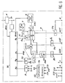
- la figure 2 est un schéma fonctionnel du module de la figure 1;
- la figure 3 un schéma de commande et de protection d'un moteur, du type à inversion du sens de marche, dans lequel est monté un second mode de réalisation du module selon l'invention;
- la figure 4 est un schéma fonctionnel du module de la figure 3;
- la figure 5 est un schéma de commande et de protection d'un moteur, du type à démarrage étoile-triangle, dans lequel est monté un troisième mode de réalisation du module interface selon l'invention;
- la figure 6 est un schéma fonctionnel du module de la figure 5.
- Le dispositif selon l'invention sert à commander un moteur électrique triphasé M alimenté par une ligne triphasée L1, L2, L3. Ce dispositif comprend un appareillage électrique de commande et protection moteur C servant à commander le moteur M et à le protéger, cet ensemble étant piloté, via un module ou coupleur d'interface 1, par un réseau de terrain de type ASI (initiales de "Actuator Sensor Interface").
- L'appareillage électrique C qui constitue un départ moteur comporte un appareil de protection D du moteur (disjoncteur moteur, etc) et un ou plusieurs contacteurs KM1, KM2, KM3. Ces différents appareils peuvent être séparés ou groupés partiellement ou totalement dans un seul appareil capable d'assurer les fonctions précédentes. L'appareil de protection D comporte un module de protection magnéto-thermique ou est associé à un relais thermique. Il peut être constitué d'appareils séparés.
- Un contact ou capteur TOR de sécurité a6 est associé au moteur M de manière à fournir un signal dit de "sécurité" sur une entrée S du module I. L'appareil de protection D est associé à un contact auxiliaire a4 et à un contact auxiliaire a5.
- Dans le mode de réalisation des figures 1 et 2 qui est adapté à un démarrage direct, l'appareillage électrique C ne comporte qu'un contacteur KM1.
- Dans le mode de réalisation des figures 3 et 4 qui est adapté à une commande avec inversion du sens de marche, l'appareillage électrique C comporte deux contacteurs KM1 et KM2. Les contacts auxiliaires a1 et a2 sont associés respectivement aux contacteurs KM1 et KM2.
- Dans le mode de réalisation des figures 5 et 6 qui est adapté à un démarrage étoile-triangle, l'appareillage électrique C comporte trois contacteurs KM1, KM2, KM3. Les contacts auxiliaires a1, a2, a3 sont associés respectivement aux contacteurs KM1, KM2 et KM3.
- Les contacts auxiliaires pourraient être remplacés par des capteurs TOR.
- L'appareillage électrique C est piloté au moyen du bus de terrain B de type ASI dont le support physique est constitué de 2 fils véhiculant les signaux d'information et l'alimentation des capteurs et actionneurs. Un cerveau de commande non représenté (P.C., automate programmable, etc.) pilote le réseau dont fait partie le bus B, la connexion entre ce cerveau et le bus étant faite par un module d'interface appelé module "maître".
- Les bobines des contacteurs (ou actionneurs) et les contacts (ou capteurs TOR) de l'appareillage électrique C se branchent sur le module ou coupleur d'interface I qui est raccordé par une connexion 1 aux 2 fils du bus B. Ce module d'interface I dit module "esclave" comprend une unité de commande 2 qui décode les demandes du module maître, gère les informations arrivant sur les entrées et génère les commandes sur les sorties et les réponses sur le bus. Cette unité de commande 2 comporte un circuit intégré 21 pourvu de 4 broches de données (entrées ou sorties), de 4 broches pour les paramètres et de 2 sorties de commande. Les broches de données repérées D0, D1, D2, D3 servent à envoyer des signaux binaires sur les bobines ou à recevoir des signaux binaires des contacts auxiliaires.
- Les informations de contrôle venant des contacts auxiliaires de l'appareillage C arrivent sur des entrées A, T, LI1, etc.. Les informations de commande destinées aux bobines ou actionneurs de l'appareillage C sont délivrées par des sorties LO1, etc. Ces différentes entrées/sorties qui permettent les connexions avec les capteurs ou actionneurs de l'appareillage C, sont reliées, via des circuits d'interface d'entrée ou de sortie, 3e ou 3s respectivement, aux broches de données D0, D1, D2, D3 du circuit intégré 2. Ces circuits d'interface 3e ou 3s assurent l'adaptation des tensions (24 volts - 5 volts) entre les circuits électroniques internes du module et les entrées ou sorties.
- Dans les modes de réalisation représentés sur les dessins, le module I est distinct de l'appareillage C. Les entrées et sorties A, T, etc. sont alors des bornes ou des pièces de connexion permettant de connecter les fils de câblage prévus entre le module I et les contacts auxiliaires ou les bobines.
- En variante, le module I peut être intégré à l'appareillage électrique C. Le câblage entre le module et l'appareillage est alors supprimé et il n'y a plus alors qu'à assurer le connexion entre l'ensemble appareillage- module et le bus.
- Le module comprend une interface 4 séparant les données de l'alimentation, contrôlant l'impédance du bus et comprenant par ailleurs un dispositif qui reçoit les informations présentes sur le bus B et les traite de manière à les envoyer sur l'unité de contrôle 2 ou qui traite les informations provenant de cette unité de contrôle 2 pour les envoyer sur le bus B.
- Une broche DSTB du circuit intégré 21 est reliée à un circuit auxiliaire 6 de surveillance, le chien de garde, qui, lorsque le dialogue est coupé entre le module maître et le module esclave (plus d'échanges), provoque une commande d'arrêt sur le ou les contacteur(s) contrôlant la marche ou l'arrêt. Ce circuit auxiliaire 6 reçoit le signal DSTB du circuit intégré 21 et fournit un signal d'alarme à un circuit logique 8 recevant par ailleurs le signal de commande de la broche D0 du circuit intégré 21 qui, on le verra plus loin, commande le fonctionnement en marche ou arrêt. Ce circuit logique 8 pilote un circuit d'interface 3s.
- Le module I comporte un organe de commande locale 7 monté sur le module et permettant de sélectionner, de manière manuelle, différents modes de fonctionnement. Cet organe est par exemple constitué par un bouton ou une manette de commande .
- Des broches de données du circuit intégré 21 ont des fonctions communes quels que soient les modules. Ces broches sont les suivantes:
- la broche D3 reçoit les signaux venant d'une entrée A qui est reliée au contact auxiliaire de signalisation a4 détectant le bon ordre de marche de l'appareil de protection D ou "disponibilité". Un dispositif additionnel peut éventuellement indiquer sur cette broche D3 si la ligne L1, L2, L3 est sous tension ou hors tension.
- la broche D2 reçoit le signal d'une entrée T qui est reliée au contact auxiliaire de signalisation a5 associé à l'appareil de protection D et/ou un dispositif de mesure de l'échauffement local (sondes thermiques). Le signal appliqué, en entrée, sur cette broche D2 indique si un courant de défaut a été détecté, de l'appareil de protection D au moteur.
- la broche D1 reçoit un signal de commande tout ou rien indiquant l'ouverture ou la fermeture d'un contacteur.
- la broche D0 fournit un signal tout ou rien commandant la marche ou l'arrêt.
- Le tableau ci-dessous résume le configuration des broches ou des bits de données pour les différents types de départs moteurs.

- Dans le tableau ci-dessus, M/A signifie marche/arrêt et O/F ouvert/fermé.
- Dans le module des figures 1 et 2, le contact auxiliaire a4 du dispositif de protection est connecté à l'entrée A du module (broche D3). Le contact auxiliaire a5 de l'appareil de protection D est connecté à l'entrée T du module (broche D2). Le contact auxiliaire a1 du contacteur KM1 est connecté à l'entrée LI1 du module (broche D1).
- La sortie LO1 (broche DO) du module est reliée à une borne de la bobine du contacteur KM1 dont l'autre borne est reliée à la masse (COM). L'organe de commande 7 comporte une position "Arrêt" ou "OFF", une position "Marche" ou "ON" et une position "Li" (qui correspond à la commande à distance par le biais du bus)
- Le circuit de logique 8 qui contrôle le signal sur la sortie LO1 reçoit, outre la sortie de la broche DO, le signal d'alarme du circuit de surveillance 6 et la sortie de l'organe de commande locale 7.
- Un circuit de logique 9 reçoit, outre le signal Li de l'organe de commande locale 7, les signaux des entrées S et A. Le bit D3 prend un état correspondant à la disponibilité de l'appareil de protection.
- Dans le module des figures 3 et 4, le contact auxiliaire a4 de l'appareil de protection D est connecté à l'entrée A du module (broche D3). Le contact auxiliaire a5 du module magnéto-thermique F1-F2 est connecté à l'entrée T du module. Le contact auxiliaire a1 du contacteur KM1 (détection de marche avant) et le contact auxiliaire a2 du contacteur KM2 (détection de marche arrière) sont connectés aux entrées LI1 et LI2 respectivement.
- Les sorties LO1 (commande de marche avant) et LO2 (commande de marche arrière) sont connectées aux bobines des contacteurs KM1 et KM2 respectivement. Les deux broches D0 et D1 sont des broches de données bidirectionnelles.
- L'organe de commande locale 7 peut prendre une position "Arrêt" ou "OFF", une position "Marche" ou "ON" et une position "Li" (commande à distance) et est associé à un second organe de commande pouvant prendre une position "marche avant" ou "AV", une position "arrêt" ou "OFF" et une position "marche arrière" ou "AR".
- Le circuit 10 qui reçoit les signaux des entrées LI1 et LI2 affecte le bit D1 soit en état "marche' ou en état "arrêt" et affecte le bit D0 soit en état "marche avant" soit en état "marche arrière". Le bit D1 contrôle la "marche" ou "l'arrêt" et le bit D0 contrôle soit la "marche avant" soit la "marche arrière". Le circuit 15 gère l'échange bidirectionnel de données sur les broches D0 et D1.
- Le circuit de commutation 8, en fonction de l'état du bit D1 et de l'état du bit D0, active soit la sortie LO1(marche avant) soit la sortie LO2 (marche arrière) ou selon l'état du bit D1 commande la marche/arrêt. Ce circuit 8 reçoit le signal de sortie du circuit de surveillance 6 de manière à mettre les sorties LO1 et LO2 en "arrêt" si le signal d'alarme est émis par le circuit de surveillance 6. Un circuit 14 gère la commutation "avant"-"arrière", sans arrêt.
- Le circuit de logique 9 reçoit, outre le signal Li de l'organe de commande locale 7, les signaux des entrées S et A. Le bit D3 prend un état correspondant à la disponibilité de l'appareil de protection.
- Dans le module des figures 5 et 6, le contact auxiliaire a4 de l'appareil de protection D est connecté à l'entrée A du module (broche D3). Le contact auxiliaire a5 de l'appareil de protection D est connecté à l'entrée T du module. Le contact auxiliaire a2 associé au contacteur KM2 (marche/arrêt) est connecté à l'entrée LI2, tandis que le contact auxiliaire a1 du contacteur KM1 (démarrage en étoile) est connecté à l'entrée LI1 et que le contact auxiliaire a3 du contacteur KM3 (démarrage en triangle) est connecté à l'entrée LI3.
- La sortie LO2 est reliée à la bobine du contacteur KM2 commandant la marche-arrêt tandis que la sortie LO1 est reliée à la bobine du contacteur KM1 (démarrage en étoile) et que la sortie LO3 est reliée à la bobine du contacteur KM3 (démarrage en triangle).
- L'organe de commande 7 peut prendre une position "Arrêt" ou "OFF", une position "Marche" ou "ON" et une position "Li" (commande à distance par le bus).
- Le circuit de commutation 8 qui contrôle les signaux de sortie sur les sorties LO1, L02, LO3 reçoit le signal d'alarme du circuit de surveillance 6, la sortie de l'organe de commande locale 7 et la sortie de la broche DO. Il reçoit également une information de temporisation nécessaire aux commutations du démarreur étoile/triangle.
- Le circuit 9 reçoit, outre le signal Li de l'organe de commande locale 7, les signaux des entrées S et A. La sortie de ce circuit 9 est envoyée sur la broche D3. Le bit D3 prend un état correspondant à la "disponibilité" signifiant que l'installation est en ordre de marche.
- Le circuit 12 de surveillance de séquence reçoit les signaux d'entrée des entrées LI1, LI2, LI3 et fournit en sortie un signal de validation à une porte ET 13 recevant le signal de l'entrée T, cette porte étant connectée à la broche de donnée D2. Toute la séquence de démarrage étoile-triangle est suivie et lorsqu'elle s'est bien passée le circuit 12 envoie le signal de validation.
- Il est bien entendu que l'on peut, sans sortir du cadre de l'invention, imaginer des variantes et des perfectionnements de détail et de même envisager l'emploi de moyens équivalents.
Claims (8)
- Module d'interface entre un bus de terrain (B) et un appareillage électrique (C) de commande et protection d'un moteur électrique (M), ce module comportant un circuit intégré (21) pourvu de broches de données (D0, D1, D2, D3) reliées via des circuits d'entrée/sortie (3) à des contacts ou capteurs TOR (a1, a2, a3, a4, a5, a6) ou à des bobines ou actionneurs (KM1, KM2, KM3) de l'appareillage électrique (C), caractérisé par le fait que les broches de données (D0, D1, D2, D3) du circuit intégré (21) sont connectées, via des circuits logiques, à des entrées ou sorties (A, T, LI1, LI2, LO1, LO2, S) dont le nombre est supérieur à celui du nombre de broches de données (D0, D1, D2, D3), ces entrées/sorties étant connectées aux bobines ou actionneurs (KM1, KM2, KM3) et aux contacts auxiliaires ou capteurs TOR (a1, a2, a 3, a4, a5, a6) de l'appareillage électrique (C).
- Module selon la revendication 1 ou 2, caractérisé par le fait que chaque broche d'entrée/sortie des données (D0, D1, D2, D3) couvre une commande ou un état standardisé pour tous les types de départs moteurs.
- Module selon la revendication 4, caractérisé par le fait qu'une première broche de données (D0) correspond à un bit dont l'état définit la marche ou l'arrêt, que la seconde broche de données (D1) correspond à un bit dont l'état définit l'ouverture ou la fermeture, que la troisième broche de données (D2) correspond à un bit dont l'état définit un défaut ou un non-défaut, que la quatrième broche de données (D3) correspond à un bit dont l'état définit l'état de marche.
- Module selon l'une quelconque des revendications précédentes, caractérisé par le fait qu'il comporte un circuit logique de surveillance (6) détectant l'absence de dialogue entre le module (I) et le bus (B) et agissant sur un circuit de logique (8) contrôlant la ou les sorties de fonctionnement en marche/arrêt.
- Module d'interface selon l'une quelconque des revendications 1 à 4, caractérisé par le fait que la première broche et la seconde broche de données (D0, D1) du circuit intégré (21) sont bidirectionnelles et sont connectées, via un circuit logique (8), à deux sorties (LO1, LO2) destinées à être connectés à des bobines ou actionneurs (KM1,KM2) de l'appareillage électrique (C) qui est du type à inversion et sont connectées, via un circuit logique (10), à deux entrées (LI1, LI2) destinées à être connectées à des contacts ou capteurs TOR (a1, a2) associés auxdits actionneurs ou bobines.
- Module d'interface selon l'une quelconque des revendications 1 à 4, caractérisé par le fait que le circuit intégré (21) est relié, par une première broche de données (D0) et via un circuit logique (8), à trois sorties (LO1, LO2, LO3) destinées à être connectés à des bobines ou actionneurs (KM1, KM2, KM3) de l'appareillage électrique (C) qui est du type à démarrage étoile-triangle.
- Module d'interface selon la revendication 6, caractérisé par le fait qu'il comporte un circuit de surveillance du séquencement (12) dont la sortie est reliée à une troisième broche de données (D2) du circuit intégré et recevant les signaux des trois entrées (LI1, LI2, LI3) connectées aux contacts auxiliaires de l'appareillage (C).
- Module d'interface selon l'une quelconque des revendications précédentes, caractérisé par le fait qu'il comporte un circuit de logique (9) relié en sortie à une quatrième broche de données (D3) du circuit intégré (21) et recevant les signaux d'entrées (A, S) et de la sortie d'un organe de commande locale (7).
Applications Claiming Priority (2)
| Application Number | Priority Date | Filing Date | Title |
|---|---|---|---|
| FR9503867 | 1995-04-03 | ||
| FR9503867A FR2732523B1 (fr) | 1995-04-03 | 1995-04-03 | Module d'interface entre un bus de terrain et un appareillage electrique de commande et de protection d'un moteur electrique |
Publications (2)
| Publication Number | Publication Date |
|---|---|
| EP0736946A1 true EP0736946A1 (fr) | 1996-10-09 |
| EP0736946B1 EP0736946B1 (fr) | 2000-03-08 |
Family
ID=9477662
Family Applications (1)
| Application Number | Title | Priority Date | Filing Date |
|---|---|---|---|
| EP96400682A Expired - Lifetime EP0736946B1 (fr) | 1995-04-03 | 1996-03-29 | Module d'interface entre un bus de terrain et un appareillage électrique de commande et de protection d'un moteur électrique |
Country Status (5)
| Country | Link |
|---|---|
| US (1) | US5955859A (fr) |
| EP (1) | EP0736946B1 (fr) |
| DE (1) | DE69606898T2 (fr) |
| ES (1) | ES2144216T3 (fr) |
| FR (1) | FR2732523B1 (fr) |
Cited By (9)
| Publication number | Priority date | Publication date | Assignee | Title |
|---|---|---|---|---|
| FR2763180A1 (fr) * | 1997-05-09 | 1998-11-13 | Schneider Electric Sa | Procede et appareil de commande d'un depart-moteur communiquant avec un bus |
| EP0889569A3 (fr) * | 1997-06-30 | 2000-04-26 | ABBPATENT GmbH | Appareillage d'installation |
| EP1104080A3 (fr) * | 1999-11-26 | 2002-08-28 | SEW-EURODRIVE GMBH & CO. | Couvercle pour un boítier de connection d'un moteur électrique |
| EP1056180A3 (fr) * | 1999-05-27 | 2003-03-19 | ABB PATENT GmbH | Disjoncteur de moteur pour moteur électrique |
| EP1037353A3 (fr) * | 1999-03-12 | 2003-08-27 | Eaton Corporation | Commande d'une bobine pour protection de surcharge de moteur |
| EP2683047A1 (fr) * | 2012-07-03 | 2014-01-08 | Siemens Aktiengesellschaft | Dispositif de protection d'un consommateur |
| CN103821996A (zh) * | 2014-02-27 | 2014-05-28 | 辽宁工程技术大学 | 一种电磁换向阀组控制器及其控制方法 |
| RU181885U1 (ru) * | 2018-03-22 | 2018-07-26 | Федеральное государственное бюджетное образовательное учреждение высшего образования "Кубанский государственный аграрный университет им. И.Т. Трубилина" | Установка подсушки изоляции обмоток и компенсации реактивной мощности трехфазного асинхронного электродвигателя |
| RU181888U1 (ru) * | 2018-03-23 | 2018-07-26 | Федеральное государственное бюджетное образовательное учреждение высшего образования "Кубанский государственный аграрный университет им. И.Т. Трубилина" | Устройство управления компенсацией и подсушкой асинхронного двигателя |
Families Citing this family (18)
| Publication number | Priority date | Publication date | Assignee | Title |
|---|---|---|---|---|
| DK1086408T3 (da) * | 1998-06-10 | 2003-05-26 | Siemens Ag | Styreindretning til en maskine, et system eller et apparat og en fremgangsmåde til overvågning af styreindretningen. |
| DE59903495D1 (de) | 1998-09-30 | 2003-01-02 | Siemens Ag | Vorrichtung zur steuerung und/oder überwachung externer technischer prozesse |
| US6541954B1 (en) | 1999-06-01 | 2003-04-01 | Ssac, Inc. | Circuit apparatus for sensing line conditions in a three phase power line |
| EP1202146A1 (fr) * | 2000-10-23 | 2002-05-02 | Lucent Technologies Inc. | Système de commande de paramètres électriques de composants de circuits |
| FR2820899B1 (fr) * | 2001-02-09 | 2003-04-04 | Schneider Electric Ind Sa | Dispositif de depart-moteur a additif |
| DE10203203B4 (de) * | 2001-07-23 | 2005-09-22 | Ifm Electronic Gmbh | Elektrische Meßeinrichtung |
| US6831465B2 (en) * | 2001-07-23 | 2004-12-14 | I F M Electronic Gmbh | Electrical measurement means |
| US7319921B2 (en) * | 2002-05-22 | 2008-01-15 | Underwood Fred R | Water treatment control system |
| ES2251277B1 (es) * | 2003-08-21 | 2007-07-16 | Talleres Foro, S.A. | Linea de esmaltado para piezas ceramicas. |
| CN100413170C (zh) * | 2004-12-08 | 2008-08-20 | 上海电器科学研究所(集团)有限公司 | 电动机控制保护装置 |
| US7802037B2 (en) * | 2008-11-05 | 2010-09-21 | General Electric Company | Control of an actuator-sensor-interface compatible device using a remote intelligence device |
| CN101867335A (zh) * | 2010-07-14 | 2010-10-20 | 蔡甫寒 | 数显电动机星/三角转换节能保护器 |
| US8885516B2 (en) | 2010-10-07 | 2014-11-11 | Schweitzer Engineering Laboratories, Inc. | Systems and methods for extending a deterministic fieldbus network over a wide area |
| US8688247B2 (en) | 2011-04-06 | 2014-04-01 | Rockwell Automation Technologies, Inc. | Lock-out, tag-out system using safety programmable logic controller |
| KR101238056B1 (ko) | 2011-11-25 | 2013-02-27 | 엘에스산전 주식회사 | 통신 모듈을 구비한 모터스타터 |
| DE102011088516A1 (de) * | 2011-12-14 | 2013-06-20 | Siemens Aktiengesellschaft | Vorrichtung zum sicherheitsgerichteten Ansteuern eines Schaltgerätes über ein AS-i System |
| DE102013208067B4 (de) * | 2013-05-02 | 2022-01-13 | Ge Energy Power Conversion Gmbh | Mehrphasige elektrische Schaltung |
| US10967303B2 (en) | 2018-03-08 | 2021-04-06 | Mark W. Romers | Filter backwash control system for a water or wastewater treatment system to conserve water during the filter backwash process |
Citations (2)
| Publication number | Priority date | Publication date | Assignee | Title |
|---|---|---|---|---|
| EP0391143A2 (fr) * | 1989-04-03 | 1990-10-10 | Siemens Aktiengesellschaft | Appareil de surveillance avec dispositif de commutation |
| DE9311725U1 (de) * | 1993-08-06 | 1993-10-07 | Ringel, Dirk, Dipl.-Ing., 06484 Quedlinburg | Steuerung für Heizprozesse |
Family Cites Families (7)
| Publication number | Priority date | Publication date | Assignee | Title |
|---|---|---|---|---|
| US4257103A (en) * | 1977-11-16 | 1981-03-17 | Heian Iron Works, Ltd. | Apparatus for controlling position of a plurality of machining shafts each including a machine tool fitted thereto |
| US4689541A (en) * | 1986-07-22 | 1987-08-25 | The United States Of America As Represented By The United States Department Of Energy | Method and apparatus for controlling multiple motors |
| US4962338A (en) * | 1986-11-20 | 1990-10-09 | Staubli International Ag. | Universal robot control board configuration |
| US4931712A (en) * | 1988-12-28 | 1990-06-05 | Pitney Bowes Inc. | Multiple channel servo configuration |
| US5122720A (en) * | 1989-12-01 | 1992-06-16 | Martinsound Technologies, Inc. | Automated fader system |
| EP0457942B1 (fr) * | 1990-05-22 | 1995-01-25 | Siemens Aktiengesellschaft | Commande pour une machine-outil ou un robot |
| US5237250A (en) * | 1991-11-01 | 1993-08-17 | Zeile Kim A | Multiplexed stepper motor control apparatus |
-
1995
- 1995-04-03 FR FR9503867A patent/FR2732523B1/fr not_active Expired - Fee Related
-
1996
- 1996-03-29 EP EP96400682A patent/EP0736946B1/fr not_active Expired - Lifetime
- 1996-03-29 DE DE69606898T patent/DE69606898T2/de not_active Expired - Lifetime
- 1996-03-29 ES ES96400682T patent/ES2144216T3/es not_active Expired - Lifetime
- 1996-04-02 US US08/626,778 patent/US5955859A/en not_active Expired - Lifetime
Patent Citations (2)
| Publication number | Priority date | Publication date | Assignee | Title |
|---|---|---|---|---|
| EP0391143A2 (fr) * | 1989-04-03 | 1990-10-10 | Siemens Aktiengesellschaft | Appareil de surveillance avec dispositif de commutation |
| DE9311725U1 (de) * | 1993-08-06 | 1993-10-07 | Ringel, Dirk, Dipl.-Ing., 06484 Quedlinburg | Steuerung für Heizprozesse |
Cited By (12)
| Publication number | Priority date | Publication date | Assignee | Title |
|---|---|---|---|---|
| FR2763180A1 (fr) * | 1997-05-09 | 1998-11-13 | Schneider Electric Sa | Procede et appareil de commande d'un depart-moteur communiquant avec un bus |
| US6294889B1 (en) | 1997-05-09 | 2001-09-25 | Schneider Electric Sa | Process and a control device for a motor output suitable for being controlled through a communication bus |
| EP0889569A3 (fr) * | 1997-06-30 | 2000-04-26 | ABBPATENT GmbH | Appareillage d'installation |
| EP1037353A3 (fr) * | 1999-03-12 | 2003-08-27 | Eaton Corporation | Commande d'une bobine pour protection de surcharge de moteur |
| EP1056180A3 (fr) * | 1999-05-27 | 2003-03-19 | ABB PATENT GmbH | Disjoncteur de moteur pour moteur électrique |
| EP1104080A3 (fr) * | 1999-11-26 | 2002-08-28 | SEW-EURODRIVE GMBH & CO. | Couvercle pour un boítier de connection d'un moteur électrique |
| EP2249464A3 (fr) * | 1999-11-26 | 2013-07-24 | SEW-EURODRIVE GmbH & Co. KG | Couvercle pour un boîtier de connection d'un moteur électrique |
| EP2683047A1 (fr) * | 2012-07-03 | 2014-01-08 | Siemens Aktiengesellschaft | Dispositif de protection d'un consommateur |
| WO2014005770A1 (fr) * | 2012-07-03 | 2014-01-09 | Siemens Aktiengesellschaft | Dispositif de protection d'un consommateur |
| CN103821996A (zh) * | 2014-02-27 | 2014-05-28 | 辽宁工程技术大学 | 一种电磁换向阀组控制器及其控制方法 |
| RU181885U1 (ru) * | 2018-03-22 | 2018-07-26 | Федеральное государственное бюджетное образовательное учреждение высшего образования "Кубанский государственный аграрный университет им. И.Т. Трубилина" | Установка подсушки изоляции обмоток и компенсации реактивной мощности трехфазного асинхронного электродвигателя |
| RU181888U1 (ru) * | 2018-03-23 | 2018-07-26 | Федеральное государственное бюджетное образовательное учреждение высшего образования "Кубанский государственный аграрный университет им. И.Т. Трубилина" | Устройство управления компенсацией и подсушкой асинхронного двигателя |
Also Published As
| Publication number | Publication date |
|---|---|
| ES2144216T3 (es) | 2000-06-01 |
| DE69606898T2 (de) | 2000-07-20 |
| US5955859A (en) | 1999-09-21 |
| FR2732523B1 (fr) | 1997-04-25 |
| DE69606898D1 (de) | 2000-04-13 |
| EP0736946B1 (fr) | 2000-03-08 |
| FR2732523A1 (fr) | 1996-10-04 |
Similar Documents
| Publication | Publication Date | Title |
|---|---|---|
| EP0736946B1 (fr) | Module d'interface entre un bus de terrain et un appareillage électrique de commande et de protection d'un moteur électrique | |
| EP0923185B1 (fr) | Dispositif d'interruption électrique comportant un module de communication | |
| CA2463779C (fr) | Module de commande et de protection d'un appareil interrupteur | |
| EP0913020B1 (fr) | Appareillage electrique debrochable comportant une partie fixe et une partie amovible debrochable installee dans la partie fixe | |
| CA2115928A1 (fr) | Dispositif a coupe-circuit commande par ordinateur et muni de circuits d'identification | |
| FR2756095A1 (fr) | Disjoncteur avec un bloc disjoncteur et des modules de traitement, de calibrage et de communication | |
| FR2827703A1 (fr) | Appareil interrupteur multipolaire de type contacteur-disjoncteur | |
| FR2645362A1 (fr) | Appareil de commande de puissance electrique | |
| EP0574300A1 (fr) | Système de commande et d'autosurveillance, en particulier pour un appareil électrique multipolaire tel qu'un disjoncteur à haute tension | |
| EP1347485B1 (fr) | Bloc additif pour contacteur-disjoncteur. | |
| EP3367523B1 (fr) | Dispositif de commande des contacts d'un interrupteur électrique | |
| EP0792096B1 (fr) | Relais électronique de protection multifonctions | |
| US6504694B1 (en) | Circuit breaker system with ASM instantaneous overcurrent indication | |
| FR3035750A1 (fr) | Dispositif de protection d'un reseau electrique | |
| EP0642198A1 (fr) | Dispositif de protection électronique d'une charge | |
| US6310753B1 (en) | Low impedance magnetic latch tripping scheme | |
| EP2577702B1 (fr) | Dispositif de commande d'une pluralite d'appareils de coupure de courant via des moteurs electriques | |
| FR2580124A1 (fr) | ||
| FR2760147A1 (fr) | Dispositif de declenchement electronique pour disjoncteur | |
| EP1517347A1 (fr) | Ensemble de départ-moteur à câblage de contrôle. | |
| EP2693585B1 (fr) | Système de protection d'une pluralité de départs électriques contre des courts-circuits, et installation électrique comprenant un tel système de protection | |
| EP3964901A1 (fr) | Interface de pilotage de disjoncteurs et interrupteurs moyenne tension | |
| FR2725557A1 (fr) | Dispositif electronique de commutation-disjonction | |
| EP2999084A1 (fr) | Dispositif d'interconnexion électrique pour inverseur de source, et inverseur de source comprenant un tel dispositif | |
| FR3030921A1 (fr) | Appareillage de protection electrique destine a equiper un tableau electrique |
Legal Events
| Date | Code | Title | Description |
|---|---|---|---|
| PUAI | Public reference made under article 153(3) epc to a published international application that has entered the european phase |
Free format text: ORIGINAL CODE: 0009012 |
|
| 17P | Request for examination filed |
Effective date: 19960403 |
|
| AK | Designated contracting states |
Kind code of ref document: A1 Designated state(s): DE ES GB IT SE |
|
| GRAG | Despatch of communication of intention to grant |
Free format text: ORIGINAL CODE: EPIDOS AGRA |
|
| GRAG | Despatch of communication of intention to grant |
Free format text: ORIGINAL CODE: EPIDOS AGRA |
|
| GRAH | Despatch of communication of intention to grant a patent |
Free format text: ORIGINAL CODE: EPIDOS IGRA |
|
| RAP1 | Party data changed (applicant data changed or rights of an application transferred) |
Owner name: SCHNEIDER ELECTRIC INDUSTRIES SA |
|
| 17Q | First examination report despatched |
Effective date: 19990714 |
|
| GRAH | Despatch of communication of intention to grant a patent |
Free format text: ORIGINAL CODE: EPIDOS IGRA |
|
| GRAA | (expected) grant |
Free format text: ORIGINAL CODE: 0009210 |
|
| AK | Designated contracting states |
Kind code of ref document: B1 Designated state(s): DE ES GB IT SE |
|
| RAP2 | Party data changed (patent owner data changed or rights of a patent transferred) |
Owner name: SCHNEIDER ELECTRIC INDUSTRIES SA |
|
| REF | Corresponds to: |
Ref document number: 69606898 Country of ref document: DE Date of ref document: 20000413 |
|
| ITF | It: translation for a ep patent filed | ||
| REG | Reference to a national code |
Ref country code: ES Ref legal event code: FG2A Ref document number: 2144216 Country of ref document: ES Kind code of ref document: T3 |
|
| GBT | Gb: translation of ep patent filed (gb section 77(6)(a)/1977) |
Effective date: 20000608 |
|
| PLBE | No opposition filed within time limit |
Free format text: ORIGINAL CODE: 0009261 |
|
| STAA | Information on the status of an ep patent application or granted ep patent |
Free format text: STATUS: NO OPPOSITION FILED WITHIN TIME LIMIT |
|
| 26N | No opposition filed | ||
| REG | Reference to a national code |
Ref country code: GB Ref legal event code: IF02 |
|
| REG | Reference to a national code |
Ref country code: DE Ref legal event code: R084 Ref document number: 69606898 Country of ref document: DE Effective date: 20111228 |
|
| PGFP | Annual fee paid to national office [announced via postgrant information from national office to epo] |
Ref country code: GB Payment date: 20120320 Year of fee payment: 17 Ref country code: SE Payment date: 20120327 Year of fee payment: 17 Ref country code: IT Payment date: 20120326 Year of fee payment: 17 |
|
| PGFP | Annual fee paid to national office [announced via postgrant information from national office to epo] |
Ref country code: ES Payment date: 20120323 Year of fee payment: 17 |
|
| REG | Reference to a national code |
Ref country code: SE Ref legal event code: EUG |
|
| PG25 | Lapsed in a contracting state [announced via postgrant information from national office to epo] |
Ref country code: SE Free format text: LAPSE BECAUSE OF NON-PAYMENT OF DUE FEES Effective date: 20130330 |
|
| GBPC | Gb: european patent ceased through non-payment of renewal fee |
Effective date: 20130329 |
|
| PG25 | Lapsed in a contracting state [announced via postgrant information from national office to epo] |
Ref country code: GB Free format text: LAPSE BECAUSE OF NON-PAYMENT OF DUE FEES Effective date: 20130329 |
|
| PG25 | Lapsed in a contracting state [announced via postgrant information from national office to epo] |
Ref country code: IT Free format text: LAPSE BECAUSE OF NON-PAYMENT OF DUE FEES Effective date: 20130329 |
|
| PGFP | Annual fee paid to national office [announced via postgrant information from national office to epo] |
Ref country code: DE Payment date: 20140210 Year of fee payment: 19 |
|
| REG | Reference to a national code |
Ref country code: ES Ref legal event code: FD2A Effective date: 20140609 |
|
| PG25 | Lapsed in a contracting state [announced via postgrant information from national office to epo] |
Ref country code: ES Free format text: LAPSE BECAUSE OF NON-PAYMENT OF DUE FEES Effective date: 20130330 |
|
| REG | Reference to a national code |
Ref country code: DE Ref legal event code: R119 Ref document number: 69606898 Country of ref document: DE |
|
| PG25 | Lapsed in a contracting state [announced via postgrant information from national office to epo] |
Ref country code: DE Free format text: LAPSE BECAUSE OF NON-PAYMENT OF DUE FEES Effective date: 20151001 |