EP0736955A2 - Méthode et appareillages pour placer des isolements dans des éléments de machines dynamo-électriques - Google Patents
Méthode et appareillages pour placer des isolements dans des éléments de machines dynamo-électriques Download PDFInfo
- Publication number
- EP0736955A2 EP0736955A2 EP96105331A EP96105331A EP0736955A2 EP 0736955 A2 EP0736955 A2 EP 0736955A2 EP 96105331 A EP96105331 A EP 96105331A EP 96105331 A EP96105331 A EP 96105331A EP 0736955 A2 EP0736955 A2 EP 0736955A2
- Authority
- EP
- European Patent Office
- Prior art keywords
- strip
- length
- clamp
- stroke
- clamp assembly
- Prior art date
- Legal status (The legal status is an assumption and is not a legal conclusion. Google has not performed a legal analysis and makes no representation as to the accuracy of the status listed.)
- Withdrawn
Links
Images



Classifications
-
- H—ELECTRICITY
- H02—GENERATION; CONVERSION OR DISTRIBUTION OF ELECTRIC POWER
- H02K—DYNAMO-ELECTRIC MACHINES
- H02K15/00—Processes or apparatus specially adapted for manufacturing, assembling, maintaining or repairing of dynamo-electric machines
- H02K15/10—Applying solid insulation to windings, stators or rotors, e.g. applying insulating tapes
-
- Y—GENERAL TAGGING OF NEW TECHNOLOGICAL DEVELOPMENTS; GENERAL TAGGING OF CROSS-SECTIONAL TECHNOLOGIES SPANNING OVER SEVERAL SECTIONS OF THE IPC; TECHNICAL SUBJECTS COVERED BY FORMER USPC CROSS-REFERENCE ART COLLECTIONS [XRACs] AND DIGESTS
- Y10—TECHNICAL SUBJECTS COVERED BY FORMER USPC
- Y10T—TECHNICAL SUBJECTS COVERED BY FORMER US CLASSIFICATION
- Y10T29/00—Metal working
- Y10T29/51—Plural diverse manufacturing apparatus including means for metal shaping or assembling
- Y10T29/5136—Separate tool stations for selective or successive operation on work
- Y10T29/5137—Separate tool stations for selective or successive operation on work including assembling or disassembling station
- Y10T29/5142—Separate tool stations for selective or successive operation on work including assembling or disassembling station and means to sever work from supply
-
- Y—GENERAL TAGGING OF NEW TECHNOLOGICAL DEVELOPMENTS; GENERAL TAGGING OF CROSS-SECTIONAL TECHNOLOGIES SPANNING OVER SEVERAL SECTIONS OF THE IPC; TECHNICAL SUBJECTS COVERED BY FORMER USPC CROSS-REFERENCE ART COLLECTIONS [XRACs] AND DIGESTS
- Y10—TECHNICAL SUBJECTS COVERED BY FORMER USPC
- Y10T—TECHNICAL SUBJECTS COVERED BY FORMER US CLASSIFICATION
- Y10T29/00—Metal working
- Y10T29/51—Plural diverse manufacturing apparatus including means for metal shaping or assembling
- Y10T29/5192—Armature
Definitions
- This invention relates to methods and apparatus for making dynamo-electric machine parts, and more particularly to methods and apparatus for inserting insulators or similar components into dynamo-electric machine parts such as electric motor armatures and stators.
- insulating material is used herein as a generic term for any web-like liner or insert, whether for insulation, coil stabilization, and/or any other generally similar purpose.
- slot is used herein as a generic term for any area of a dynamo-electric machine part requiring the insertion of insulating material.
- a “slot” may be the space between two poles on the core of a dynamo-electric machine armature or stator, either before or after coils have been wound on that core.
- a “slot” may thus have any of a wide variety of shapes.
- the insulating material is fed out lengthwise from a continuous supply between intermittently driven rollers.
- the intermittent drive of the rollers is such that feeding stops each time the required length of insulating material has been fed out.
- the fed out length is then cut off, formed into the required shape, and inserted into the slot.
- a problem with this technique is that as machine speed increases in order to increase productivity, it becomes increasingly difficult to precisely control the length of the insulating material fed out. Precise length control is desirable to make sure that the entire slot is insulated, but that there is no wasteful, unsightly, and possibly hazardous excess of insulating material extending beyond the ends of the slot.
- Intermittent roller drive is difficult to control at high machine speeds because of the large inertia of the rollers. This in turn is deleterious to precise control of the length of the insulating material fed out, and therefore cut off and inserted in the slots. It is also typically relatively difficult and time-consuming to adjust these prior art machines for different dynamo-electric machine parts requiring different lengths of insulating material. For example, there may be a complex geometric relationship between the sizes or shapes of various machine control parts and the length of the insulating material fed out.
- Machines of the type shown in Santandrea et al. U.S. patent Re. 34,195 offer a number of advantages over the other machines described above.
- insulating material is fed out by a continuously rotating drive wheel. The paper stops when its free end hits an abutment. The drive wheel then slips on the stopped insulating material. The insulating material that has been fed out is cut off for shaping and insertion into a slot, while the feeding out of material resumes.
- This machine produces very precise and easily (even automatically) adjustable insulating material lengths. At very high production rates, however, it can be difficult to use the free end of the insulating material to stop the feeding out of that material without deforming the end of the material.
- the dynamo-electric machine part may be indexed after each slot receives a length of insulating material to position the next slot in the part to receive the next length of material.
- the insulating material fed out during a forward stroke of the clamp is cut off and shaped (if necessary) during the subsequent return stroke of the clamp. That piece of insulating material is then inserted in a slot during the next forward stroke of the clamp, which next forward stroke also feeds out the next length of insulating material to be cut off.
- work is being done on the insulating material during both the forward and return strokes of the clamp.
- two lengths of insulating material are being worked on at least partly concurrently (i.e., a new length is being fed out, and the previously fed out and cut off length is being inserted in a slot).
- the insulating material can be moved more slowly than in prior art machines in which a length of insulating material must be fed out, cut off, and inserted, all before feeding out of the next length begins.
- the relatively slower motion of the insulating material in accordance with particularly preferred embodiments of this invention has many advantages such as reduced machine wear, less likelihood of damage to the insulating material, more precise stopping of the insulating material being fed out (thereby facilitating better control of the length of insulating material cut off), etc.
- the apparatus is quickly and easily adjustable to provide different lengths of insulating material because there tends to be a simple linear relationship (e.g., a one-for-one relationship) between (1) the distance between the above-mentioned first and second points and (2) the length of insulating material cut off.
- Large inertial forces of components in contact with the insulating material when that material should stop are not a factor with this invention because the insulating material is released from such components when it is to stop.
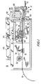
- FIG. 1 is an elevational sectional view of illustrative apparatus constructed in accordance with this invention.
- FIG. 2 is a top plan view of the apparatus shown in FIG. 1.
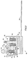
- FIG. 3 is an enlarged sectional view of a portion of the apparatus shown in FIG. 1.
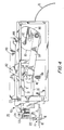
- FIG. 4 is an elevational view of the side of the apparatus which is to the rear in FIG. 1.
- FIG. 5 is an isometric view of a portion of the end of the apparatus which is on the right in FIG. 1.
- FIG. 6 is an isometric view of the same portion of the apparatus which is shown in FIG. 5, but seen from a different direction than in FIG. 5.
- FIG. 7 is similar to a portion of FIG. 3, but with the addition of several optional details.
- FIG. 8 is an elevational view, partly in section, of the end of the apparatus which is shown in FIGS. 5 and 6.
- FIG. 9 is a simplified elevational view of an alternative embodiment of a portion of the apparatus shown in the other FIGS.
- a continuous strip 10 of insulating material is supplied from the left to the illustrative apparatus 20 of this invention.
- Any suitable insulating material supply may be used.
- apparatus of the type shown on the left in FIG. 1 of Santandrea et al. U.S. patent Re. 34,195 may be used.
- Strip 10 shown entering on the left in FIG. 1 herein may be coming from the variable length loop of material 10 shown on the left in FIG. 1 of the Santandrea et al. patent.
- Strip 10 may already be longitudinally scored (to facilitate subsequent forming) when it enters apparatus 20. Such scoring of strip 10 is indicated by lines 12 in FIG. 2.
- Strip 10 passes between the upper surface of stationary platen 30 and the lower surface of pressure pad 32.
- Pressure pad 32 is resiliently biased down toward platen 30 by prestressed compression coil spring 34.
- the purpose of elements 30, 32, and 34 is to apply some constant braking or retarding force to strip 10 so that the strip stops moving as soon as it is no longer being pulled forward by reciprocating clamp assembly 40 as will now be described.
- Clamp assembly 40 includes a carriage 42 which is mounted on guide 70 for reciprocation along an axis which is parallel to the longitudinal axis of strip 10 (i.e., a left-right axis in FIG. 1).
- Clamp assembly 40 has a lower clamping jaw 44 which is fixed relative to carriage 42 and an upper clamping jaw 46 which is vertically reciprocable relative to carriage 42 (see also FIG. 3).
- Strip 10 (not shown in FIG. 3) passes between jaws 44 and 46.
- Jaw 46 is resiliently urged down toward jaw 44 by prestressed compression coil springs 48. When jaw 46 is solely under the influence of springs 48, strip 10 is firmly clamped between jaws 44 and 46.
- Jaw 46 can be lifted up out of contact with strip 10 by pivoting lever 50 counterclockwise (as viewed in FIGS. 1 and 3) about pivot shaft 52.
- Lever 50 is resiliently urged to rotate clockwise (as viewed in FIGS. 1 and 3) by prestressed compression coil spring 54.
- Lever 50 can be pivoted counterclockwise by downward force from cam follower roller 56.
- Roller 56 bears on cam surface 72 which is mounted on the stationary frame of apparatus 20.
- lever 50 When lever 50 is pivoted counterclockwise by the effect of cam surface 72, it raises upper jaw 46 via a clevis portion of the lever engaging under pin 58. (Prior to such counterclockwise pivoting there is preferably a clearance between pin 58 and the clevis portion of lever 50.)
- Pin 58 passes through a shaft 60 that extends upwardly from upper jaw 46.
- Pivoting lever 50 counterclockwise also allows latch 62 to pivot clockwise about its pivot shaft 64.
- Latch 62 is resiliently urged to pivot clockwise about shaft 64 by plunger 66, which is resiliently urged to move to the left by a prestressed compression coil spring (not shown) acting on the plunger.
- plunger 66 which is resiliently urged to move to the left by a prestressed compression coil spring (not shown) acting on the plunger.
- cam follower roller 56 bears on cam surface 72.
- cam surface 72 is farther from guide 70 than it is during a final portion of that stroke.
- the initial portion of cam surface 72 is designated B and the final portion is designated C.
- the lengths and locations of portions B and C in FIG. 1 are only illustrative and are not consistent with other features (e.g., length L) shown in that FIG.)
- lever 50 is in the position which allows jaw 46 to clamp strip 10 against jaw 44. Accordingly, clamp assembly 40 is operative to advance strip 10 to the right with the rightward-moving clamp assembly.
- lever 50 is pivoted counterclockwise, thereby lifting jaw 46 out of clamping contact with strip 10. This causes strip 10 to immediately stop (e.g., under the influence of elements 30 and 32), even though assembly 40 is continuing to move to the right.
- crank arm 84 is rotatably connected to disk 80 at a point which is radially spaced from shaft 82.
- the other end of crank arm 84 is rotatably connected to clamp assembly 40. Accordingly, rotation of disk 80 reciprocates assembly 40. In particular, each 360° revolution of disk 80 produces one forward and one backward stroke of assembly 40.
- FIG. 4 also shows that the peripheral surface 86 of disk 80 is used as a cam for operating the portion 90 of apparatus 20 that (1) cuts off the length of insulating material strip 10 that has been fed out by clamp assembly 40, (2) forms the cut off length of strip material into the shape required for insertion into a slot, and (3) indexes the dynamo-electric machine part to position the next slot to receive the next formed length of strip material.
- the dynamo-electric machine part is an armature 14 having a ferromagnetic core 16 concentrically mounted on a shaft 18.
- Armature core 16 has several axially extending slots 17 spaced from one another in the circumferential direction around the core. Each of these slots must be aligned with a length of insulating material 10 equal to the length of the slot parallel to the longitudinal axis of shaft 18.
- apparatus 20 is set up so that the distance along cam surface 72 from the point at which roller 56 contacts that surface at the start of a forward stroke of clamp assembly 40 to the transition between cam surface portions B and C is equal to the axial length of a slot 17.
- a movable portion 100 of cutting/forming/indexing assembly 90 begins to move down.
- An initial portion of this downward motion causes transversely aligned knife blade 102 to cut off length L of insulating material.
- a further portion of the downward motion of subassembly 100 causes axially aligned forming blade 104 to push cut off length L down into a stationary forming die 106 which is located beneath the forming blade.
- forming die 106 may have a shape transverse to its length which is similar to the transverse shape of one of slots 17.
- indexing pawl 110 operates to rotate armature 14 about its longitudinal axis by the amount necessary to align the next slot 17 requiring lining with the distal end of forming die 106.
- the indexing mechanism is described in more detail below in connection with FIG. 8.
- a final aspect of the operation of apparatus 20 that must be considered is the actual insertion of the cut and formed length of insulating material into a slot 17. This involves pushing the insulating material from forming die 106 into the slot 17 which is axially aligned with that die. This is accomplished by an insertion blade 150 which is carried by reciprocating clamp assembly 40. As is perhaps best seen in FIGS. 1 and 3, insertion blade 150 is attached to a lower portion of assembly 40 so that it is axially aligned with and can enter forming die 106 during a latter portion of each forward stroke of assembly 40. As the distal end of insertion blade 150 enters forming die 106, it engages the proximal end of the formed insulating material in the die and begins to push that material toward and into the axially aligned slot 17.
- insertion blade 150 has pushed the insulating material fully into slot 17, and the distal end of insertion blade 150 is accordingly immediately adjacent the proximal face of armature core 16. Assembly 40 then begins its return stroke, leaving the insulating material properly positioned in slot 17, but withdrawing insertion blade 150 from die 106. As soon as blade 150 is out of die 106, the next cut length L of insulating material can be pushed down into die 106 by forming blade 104. Thus it will be seen that the downward stroke of subassembly 100 is timed to occur during a latter portion of the return stroke of assembly 40 when insertion blade 150 is out of die 106.
- a final portion of the return stroke of assembly 40 coincides with the upward stroke of subassembly 100 so that knife blade 102 is out of the way when the feeding of strip 10 begins again at the start of the next forward stroke of assembly 40.
- the operating sequence of the apparatus is such that the insulating material inserted into a slot 17 during each forward stroke of assembly 40 is the length of insulating material fed out during the preceding forward stroke of assembly 40. That length is cut off and formed during the return stroke of assembly 40 that also precedes the forward stroke that results in insertion of that length into a slot 17.
- insertion blade 150 may be mounted on clamp assembly 40 so that if the insertion blade encounters unusually high resistance during its forward stroke, it can shift axially relative to assembly 40 in the return stroke direction.
- a first releasable detent formed by spring-loaded ball 152 in recess 154a
- a second releasable detent formed by spring-loaded ball 152 in recess 154b
- may hold insertion blade 150 in a rearward shifted position relative to assembly 40 i.e., the position shown in FIG.
- insertion blade 150 after the insertion blade has shifted due to high resistance during a forward stroke.
- the rear or proximal end of insertion blade 150 projects from the rear or proximal side of assembly 40, and this can be detected (e.g., by a proximity switch or a microswitch 156 on the stationary frame of the apparatus at or near the end of the return stroke of assembly 40). Detection of insertion blade shifting can be used to produce an alarm and to stop the machine until the malfunction has been investigated and corrected. Insertion blade 150 is then pushed back to its first detent position and operation of the apparatus is resumed.
- cam member 72 may bear on another movable cam member which has different indicated positions for different indicated lengths L.
- cam member 72 is unclamped, the other cam member mentioned in the preceding sentence is moved to the position indicated for the desired new length L, cam member 72 is pushed into contact with the other cam member, and cam member 72 is re-clamped in its new position.
- That member may simply be removed and replaced by another cam member having a different location of the transition between cam surface portions B and C.
- the length L appropriate for a particular slot length can be established automatically or semiautomatically.
- the left-hand (proximal) end of armature core 16 is always at the same location relative to apparatus 20, regardless of the length of the core.
- the length of slots 17 can be determined by sensing the location of the right-hand (distal) end of core 16 relative to apparatus 20.
- Cam member 72 can then be shifted left or right based on the sensed location of the right-hand end of core 16.
- an arm which extends forward and down to the distal end of core 16 can be attached to cam member 72. Then, with cam member 72 unclamped, this assembly is moved left or right until the arm contacts the right-hand end of core 16.
- Cam member 72 is then clamped in the resulting position and the apparatus will thereafter produce lengths L that are exactly the correct length for the slots 17 in core 16.
- Indexing pawl 110 is pivotally mounted to adjustable arm 114 via pivot shaft 112.
- Pawl 110 is resiliently urged to pivot about shaft 112 in the clockwise direction as viewed in FIG. 8 by prestressed compression coil spring 116. This resiliently inserts a tooth 111 on pawl 110 into the opening of an armature slot 17 which is adjacent to that tooth.
- Arm 114 is adjustable left or right as view in FIG. 8 by loosening bolts 118, shifting arm 114 as desired, and then retightening bolts 118. This facilitates accommodating armatures having different diameters. It also allows control of the amount by which tooth 111 enters the adjacent armature slot 17.
- Arm 114 is mounted on a frame 120 which is movable downwardly from the position shown in FIG. 8 (see also FIGS. 5 and 6).
- Frame 120 is resiliently urged to its depicted upper position by prestressed compression coil spring 122.
- Frame 120 is moved down by downward motion of above-described subassembly 100 acting on the top of rod 126 which is threaded into frame 120.
- Rod 126 is locked in place with the desired (adjustable) extension from frame 120 by nut 124.
- a clearance Prior to each downward stroke of subassembly 100 a clearance preferably exists between subassembly 100 and the top of rod 126. This helps avoid transmission of possible vibration of lever 140 to the indexing mechanism.
- assembly 90 can be readily constructed so that it is easily and rapidly removable as a unit if desired. This facilitates modification or replacement of this assembly when differently configured dynamo-electric machine parts are to be processed. For example, such changes may include different numbers or sizes of slots, requiring a change in the shape of die 106 or in the indexing motion of pawl 110. Mere changes in slot length can generally be accommodated as described in the preceding paragraphs and typically do not require modification of assembly 90.
- Machine part inertia has almost no effect on the feeding of strip 10. There are no heavy machine parts such as feed rollers to start and stop when it is desired to start and stop each strip feeding cycle. This helps the apparatus maintain very precise strip lengths L even when the machine is operated very rapidly.
- the apparatus is also quickly, easily, and straightforwardly adjustable to change length L. For example, and as has been noted, there is a linear, one-for-one relationship between length L and the location of the transition between portions B and C of cam surface 72.
- Another advantage of the depicted preferred embodiment is that a portion of the necessary work on the strip and the dynamo-electric machine part is performed during the return stroke of clamp assembly 40. This refers to the fact that the strip is cut off and formed, and the dynamo-electric machine part is indexed, during the return stroke of assembly 40. This helps to increase the production rate of the apparatus without requiring faster or longer motions of various machine components. It also makes possible an increased production rate without having to increase the speed of travel of the insulating material. This also facilitates precise control of the lengths of insulating material supplied, as well as reducing the risk of damage to those insulating material lengths.
- the machine can be very easily reorganized, if desired, so that a given length of insulating material is fed out, cut off, formed, and inserted in a slot, all during a given forward stroke of clamp assembly 40.
- the desired length of insulating material would be fed out during a first portion of the forward stroke of assembly 40.
- the fed out insulating material would then be cut off and formed during a second portion of the forward stroke of assembly 40.
- the formed insulating material would be inserted in a slot 17 during a third portion of the forward stroke of assembly 40. Only indexing of the dynamo-electric machine part would take place during the return stroke of assembly 40.
- This alternative might require a longer stroke for assembly 40, as well as different phasing between the motions of assembly 40 and subassembly 100, but it would mean that only one length of strip 10 would be in process during any one cycle of operation of the machine.
- Initial cam portion A (on which cam follower roller 56 bears during an initial portion of the forward stroke of clamp assembly 40) is preferably independent of portions B and C.
- cam portion A may be fixed to the frame of the machine, or it may be adjustable (left and right) relative to the frame of the machine independent of the above-described left-right adjustability of portions B and C.
- cam follower roller 56 to contact initial cam portion A.
- Cam portion A is prominent enough relative to cam portion B to prevent jaws 44 and 46 from clamping insulating material 10, but not so prominent that latch 62 can re-latch lever 50.
- Clamp assembly 40 therefore begins its forward stroke without clamping insulating material 10.
- the forward stroke of clamp assembly 40 proceeds without any corresponding forward motion of insulating material 10.
- roller 56 leaves portion A for portion B however, the insulating material is clamped and fed forward until roller 56 reaches the transition between regions B and C. Clamp assembly 40 then unclamps the insulating material (which stops) and the clamp assembly completes its forward stroke with no further forward motion of the insulating material.
- the starting point of insulating material 10 can be fixed (similar to the fixed starting point when portion A is omitted).
- the length L of material fed out and cut off remains adjustable by left-right adjustment of portions B and C as was described earlier.
- portion A adjustable independently of portions B and C both the point at which material 10 feeding begins and the point at which that feeding ends can be made independently adjustable.
Landscapes
- Engineering & Computer Science (AREA)
- Manufacturing & Machinery (AREA)
- Power Engineering (AREA)
- Manufacture Of Motors, Generators (AREA)
- Insulation, Fastening Of Motor, Generator Windings (AREA)
Applications Claiming Priority (2)
| Application Number | Priority Date | Filing Date | Title |
|---|---|---|---|
| US08/418,635 US5720097A (en) | 1995-04-07 | 1995-04-07 | Apparatus for inserting insulators |
| US418635 | 1995-04-07 |
Publications (2)
| Publication Number | Publication Date |
|---|---|
| EP0736955A2 true EP0736955A2 (fr) | 1996-10-09 |
| EP0736955A3 EP0736955A3 (fr) | 1999-01-27 |
Family
ID=23658938
Family Applications (1)
| Application Number | Title | Priority Date | Filing Date |
|---|---|---|---|
| EP96105331A Withdrawn EP0736955A3 (fr) | 1995-04-07 | 1996-04-03 | Méthode et appareillages pour placer des isolements dans des éléments de machines dynamo-électriques |
Country Status (3)
| Country | Link |
|---|---|
| US (1) | US5720097A (fr) |
| EP (1) | EP0736955A3 (fr) |
| CA (1) | CA2172007A1 (fr) |
Families Citing this family (4)
| Publication number | Priority date | Publication date | Assignee | Title |
|---|---|---|---|---|
| US5924351A (en) * | 1998-01-28 | 1999-07-20 | Eaton Corporation | Adjustable cut-off head for a wire and strip forming machine |
| US6834421B2 (en) * | 2000-11-14 | 2004-12-28 | Axis Usa Inc. | Apparatus for dynamo-electric machine insulation handling |
| US7604708B2 (en) * | 2003-02-14 | 2009-10-20 | Applied Materials, Inc. | Cleaning of native oxide with hydrogen-containing radicals |
| US20100270262A1 (en) * | 2009-04-22 | 2010-10-28 | Applied Materials, Inc. | Etching low-k dielectric or removing resist with a filtered ionized gas |
Family Cites Families (12)
| Publication number | Priority date | Publication date | Assignee | Title |
|---|---|---|---|---|
| GB837782A (en) * | 1957-08-12 | 1960-06-15 | Vincent Kinsman Smith | Machine for insulating dynamo-electric machine components |
| US3634932A (en) * | 1967-07-17 | 1972-01-18 | Gen Electric | Method for producing insulation in the slots of magnetic cores |
| DE1613476C3 (de) * | 1967-10-06 | 1973-12-06 | Franz 7980 Ravensburg Veser | Maschine zur Herstellung von Isolier streifen fur Elektromotoren Wicklungen |
| US3694887A (en) * | 1970-10-30 | 1972-10-03 | Ind Products Inc | Wedgemaker |
| US3778889A (en) * | 1971-05-18 | 1973-12-18 | Gen Electric | Apparatus and method for performing manufacturing operations on an article of manufacture |
| US4233729A (en) * | 1978-11-27 | 1980-11-18 | General Electric Company | Apparatus and methods for making and using slot closure wedges at a coil injection station |
| US4387001A (en) * | 1979-06-22 | 1983-06-07 | General Electric Company | Methods and apparatus for fabricating electrical phase insulators for dynamoelectric machines |
| US4305199A (en) * | 1980-03-07 | 1981-12-15 | General Electric Company | Apparatus for controlling the length of wedges |
| SU1035736A1 (ru) * | 1982-03-31 | 1983-08-15 | Базовая Лаборатория N104 Научно-Исследовательского Технологического Института | Способ изготовлени пазовой изол ционной гильзы |
| US4495692A (en) * | 1982-06-18 | 1985-01-29 | Industra Products, Inc. | Coil placing machine with readily convertible wedge making arrangement |
| IT1217170B (it) * | 1987-05-06 | 1990-03-14 | Axis Spa | Macchina per il trascinamento ed il taglio a lunghezza variabile della carta costituente il pacco isolante degli indotti di motori elettrici |
| US4854033A (en) * | 1988-06-27 | 1989-08-08 | Axis Usa Inc. | Inserting insulating material into electric motor stators |
-
1995
- 1995-04-07 US US08/418,635 patent/US5720097A/en not_active Expired - Fee Related
-
1996
- 1996-03-18 CA CA002172007A patent/CA2172007A1/fr not_active Abandoned
- 1996-04-03 EP EP96105331A patent/EP0736955A3/fr not_active Withdrawn
Also Published As
| Publication number | Publication date |
|---|---|
| US5720097A (en) | 1998-02-24 |
| EP0736955A3 (fr) | 1999-01-27 |
| CA2172007A1 (fr) | 1996-10-08 |
Similar Documents
| Publication | Publication Date | Title |
|---|---|---|
| US10554106B2 (en) | Apparatus for winding and terminating dynamo electric machine cores | |
| US4164808A (en) | Apparatus for producing sets of accurately and identically sized wire leads | |
| SU936797A3 (ru) | Устройство дл электроэрозионной обработки | |
| EP0663189B1 (fr) | Dispositif à rétreindre une aiguille chirurgicale et un fil de suture | |
| GB1118861A (en) | Wire cutting and stripping machine | |
| US6616082B2 (en) | Machine for winding dynamo-electric stators | |
| US4099316A (en) | Apparatus for inserting displation type terminals into cavities | |
| US5720097A (en) | Apparatus for inserting insulators | |
| US4253222A (en) | Apparatus for applying assembled connector terminals to a plurality of leads | |
| US20040143965A1 (en) | Machine for feeding waterproof seal members for electric wires, method for fitting waterproof seal members over electric wires, and apparatus for processing electric wires | |
| US4641421A (en) | Method of forming and installing field windings | |
| JP2602482B2 (ja) | 端子テ−プ移動手段を改良した電気端子アプリケ−タ | |
| US5379511A (en) | Armature winding method and apparatus | |
| CN112170579B (zh) | U管成型机 | |
| CN219998042U (zh) | 一种绕线机的控线机构 | |
| GB1575221A (en) | Apparatus for use in making electrical interconnections | |
| EP0098078A1 (fr) | Dispositif pour le transfert de bobines et méthode pour sa conversion | |
| US4387001A (en) | Methods and apparatus for fabricating electrical phase insulators for dynamoelectric machines | |
| CN113223835B (zh) | 变压器绕线设备 | |
| US4279277A (en) | Apparatus for manufacturing a dynamolelectric field member | |
| US4677882A (en) | Feeding means for intermittently rotating a circular saw blade of great pitch | |
| US4534098A (en) | Apparatus for applying assembled connector terminals and the like to a plurality of leads | |
| US6164584A (en) | Winding machine | |
| US5187856A (en) | Armature winding apparatus | |
| GB2035855A (en) | Making and inserting slot closure wedges for stator cores |
Legal Events
| Date | Code | Title | Description |
|---|---|---|---|
| PUAI | Public reference made under article 153(3) epc to a published international application that has entered the european phase |
Free format text: ORIGINAL CODE: 0009012 |
|
| AK | Designated contracting states |
Kind code of ref document: A2 Designated state(s): CH DE ES FR GB IT LI NL SE |
|
| PUAL | Search report despatched |
Free format text: ORIGINAL CODE: 0009013 |
|
| RHK1 | Main classification (correction) |
Ipc: H02K 15/10 |
|
| AK | Designated contracting states |
Kind code of ref document: A3 Designated state(s): CH DE ES FR GB IT LI NL SE |
|
| 17P | Request for examination filed |
Effective date: 19990726 |
|
| STAA | Information on the status of an ep patent application or granted ep patent |
Free format text: STATUS: THE APPLICATION IS DEEMED TO BE WITHDRAWN |
|
| 18D | Application deemed to be withdrawn |
Effective date: 20021102 |