EP0736992A2 - Dispositif haut parleur pour téléphones sans fil - Google Patents
Dispositif haut parleur pour téléphones sans fil Download PDFInfo
- Publication number
- EP0736992A2 EP0736992A2 EP96103724A EP96103724A EP0736992A2 EP 0736992 A2 EP0736992 A2 EP 0736992A2 EP 96103724 A EP96103724 A EP 96103724A EP 96103724 A EP96103724 A EP 96103724A EP 0736992 A2 EP0736992 A2 EP 0736992A2
- Authority
- EP
- European Patent Office
- Prior art keywords
- loudspeaker device
- base station
- loudspeaker
- telephone according
- handset
- Prior art date
- Legal status (The legal status is an assumption and is not a legal conclusion. Google has not performed a legal analysis and makes no representation as to the accuracy of the status listed.)
- Withdrawn
Links
- 230000005540 biological transmission Effects 0.000 claims abstract description 29
- 238000001514 detection method Methods 0.000 claims abstract description 3
- 230000003213 activating effect Effects 0.000 claims description 4
- 238000012544 monitoring process Methods 0.000 claims description 2
- 230000005236 sound signal Effects 0.000 claims description 2
- 238000004891 communication Methods 0.000 description 5
- 238000010586 diagram Methods 0.000 description 3
- 230000004913 activation Effects 0.000 description 2
- 230000002457 bidirectional effect Effects 0.000 description 1
- 230000009849 deactivation Effects 0.000 description 1
- 238000000034 method Methods 0.000 description 1
- 230000001629 suppression Effects 0.000 description 1
Images

Classifications
-
- H—ELECTRICITY
- H04—ELECTRIC COMMUNICATION TECHNIQUE
- H04M—TELEPHONIC COMMUNICATION
- H04M1/00—Substation equipment, e.g. for use by subscribers
- H04M1/60—Substation equipment, e.g. for use by subscribers including speech amplifiers
- H04M1/6033—Substation equipment, e.g. for use by subscribers including speech amplifiers for providing handsfree use or a loudspeaker mode in telephone sets
- H04M1/6041—Portable telephones adapted for handsfree use
-
- H—ELECTRICITY
- H04—ELECTRIC COMMUNICATION TECHNIQUE
- H04M—TELEPHONIC COMMUNICATION
- H04M1/00—Substation equipment, e.g. for use by subscribers
- H04M1/72—Mobile telephones; Cordless telephones, i.e. devices for establishing wireless links to base stations without route selection
- H04M1/725—Cordless telephones
- H04M1/72502—Cordless telephones with one base station connected to a single line
Definitions
- the invention relates to a loudspeaker device for cordless telephones, in which at least one handset is coupled wirelessly from a transmission link to a base station.
- DE 37 36 608 C1 describes a charging station for cordless telephones.
- the cordless telephone can be inserted into the charging station in such a way that the keyboard, the loudspeaker and the microphone are accessible for use.
- a loudspeaker is arranged, which can be used in combination with the cordless telephone.
- the object of the present invention is to construct a telephone of the type mentioned in the introduction in such a way that the convenience of use is increased.
- the loudspeaker device is designed as a loudspeaker which is arranged in a housing which is formed separately from the base station and separately from the mobile part and which is fed by an amplifier, in that the amplifier is connected to a receiver which is set by a controller is and which is connected to the base station via a wireless transmission link, that the control for channel monitoring has a frequency changeover which successively addresses all receivable channels in order to activate a channel identification check when a channel is detected, which activates the loudspeaker when the assigned handset is recognized and turns on detection of a sound signal and that the wireless transmission path is provided in addition to the wireless transmission path between the base station and the handset.
- the arrangement of the loudspeaker device in a housing separate from the base station and the use of the corresponding communication interfaces make it possible to provide a transportable loudspeaker device that is not tied to the connection box (TAE).
- TAE connection box
- the loudspeaker used can be of any size and has an acoustic characteristic be provided, which corresponds to the respective specifications and does not have to fit into the usually small housing of the base station.
- the loudspeaker device is provided with a release check.
- the loudspeaker device be provided with a noise cut-off.
- an identification exchange is carried out in the area of the transmission link.
- a high variability in use is supported by the fact that the loudspeaker device is provided with a battery supply.
- the loudspeaker device is provided with a mains supply.
- a button be arranged in the area of the handset for activating and deactivating the loudspeaker device.
- the loudspeaker device Operation of the loudspeaker device is made possible by the fact that the loudspeaker device is coupled to the transmission link as a secondary receiver.
- a base station (1) is connected to a junction box (2) (TAE) via a communication connection.
- the junction box (2) represents the transfer point to the communication network.
- the base station (1) is provided with an antenna (3) which spans a transmission path (4) to an antenna (5) of a mobile unit (6).
- the transmission link (4) is bidirectional and enables both sending and receiving.
- the handset (6) is conventionally provided with a keyboard (7) and additionally has a key (8) for activating or deactivating a loudspeaker device (9).
- the loudspeaker device (9) is arranged in a housing (10) which is formed separately from the base station (1).
- the loudspeaker device (9) has an antenna (11) to enable communication with the base station (1).
- a transmission path (12) is spanned between the antenna (3) and the antenna (11), which preferably permits unidirectional data transmission from the base station (1) to the loudspeaker device (9).
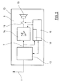
- FIG. 2 shows a block diagram of the loudspeaker device (9). It can be seen that the antenna (11) is connected to a receiver (13) which is designed as a high-frequency part. The receiver (13) is connected to an amplifier (14) which is designed as a low-frequency part. The amplifier (14) feeds a loudspeaker (15).
- the receiver (13) and the amplifier (14) are controlled by a controller (16).
- the controller (16) has an input which is connected to a connecting line (7) between the receiver (13) and the amplifier (14).
- the input signals are fed to a demodulator (18).
- Another output of the control (16) is provided for controlling a switch (19) which is arranged between the amplifier (14) and the loudspeaker (15).
- the loudspeaker device (9) can be battery-powered or mains-powered.
- the receiver (13) works as a secondary receiver (slave receiver), which can connect to an occupied channel of the transmission link (4).
- the controller (16) of the loudspeaker device (9) ensures that all channels available in the area of the transmission link (4) are scanned. This is done by frequency advancement. If an occupied channel is determined, the controller (16) checks whether there is an identifier for the associated handset (6). If this is not the case, the search process is continued. If a suitable identifier is determined, the controller (16) checks whether the identifier identified contains a release for activating the loudspeaker device (9). If this is the case, the loudspeaker (15) is controlled via the amplifier (14), in which the control (16) closes the switch (19).
- the loudspeaker device (9) is released from the handset (6) using the button (8), which can be designed either as a real electrical button or as a corresponding control input.
- the handset (6) sends the associated instructions via the transmission link (4) to the base station (1) and from here it is forwarded via the transmission link (12) to the loudspeaker device (9). In particular, it is intended to carry out the transmission of the corresponding control information about the cyclical code exchange between the base station (1) and the mobile part (6).
- the transmission of the associated control codes is intended to first carry out a transmission from the mobile part (6) to the base station (1) and then a return transmission from the base station (1) to the mobile part (6).
- the loudspeaker device (9) is automatically switched off by a noise suppression (Sqelch circuit).
- the implementation of the identification exchange helps to ensure adequate security against eavesdropping.
- several mobile parts (6) are connected to a common base station (1)
Landscapes
- Engineering & Computer Science (AREA)
- Signal Processing (AREA)
- Computer Networks & Wireless Communication (AREA)
- Mobile Radio Communication Systems (AREA)
Applications Claiming Priority (2)
| Application Number | Priority Date | Filing Date | Title |
|---|---|---|---|
| DE19512387 | 1995-04-01 | ||
| DE19512387A DE19512387C1 (de) | 1995-04-01 | 1995-04-01 | Lauthöreinrichtung für schnurlose Telefone |
Publications (1)
| Publication Number | Publication Date |
|---|---|
| EP0736992A2 true EP0736992A2 (fr) | 1996-10-09 |
Family
ID=7758627
Family Applications (1)
| Application Number | Title | Priority Date | Filing Date |
|---|---|---|---|
| EP96103724A Withdrawn EP0736992A2 (fr) | 1995-04-01 | 1996-03-09 | Dispositif haut parleur pour téléphones sans fil |
Country Status (2)
| Country | Link |
|---|---|
| EP (1) | EP0736992A2 (fr) |
| DE (1) | DE19512387C1 (fr) |
Cited By (4)
| Publication number | Priority date | Publication date | Assignee | Title |
|---|---|---|---|---|
| DE19641755A1 (de) * | 1996-10-10 | 1998-04-23 | Deutsche Telekom Ag | Schnurloser Telefonapparat |
| EP2490416A1 (fr) * | 2011-02-18 | 2012-08-22 | Gigaset Communications GmbH | Système de téléphone sans fil pour environnements multi-spatiaux |
| EP2490415A1 (fr) * | 2011-02-18 | 2012-08-22 | Gigaset Communications GmbH | Système et procédé de suivi d'émissions de haut-parleurs correspondant au mouvement spatial d'un utilisateur |
| EP2490417A1 (fr) * | 2011-02-18 | 2012-08-22 | Gigaset Communications GmbH | Dispositif de téléphonie sans fil |
Families Citing this family (2)
| Publication number | Priority date | Publication date | Assignee | Title |
|---|---|---|---|---|
| US11741093B1 (en) | 2021-07-21 | 2023-08-29 | T-Mobile Usa, Inc. | Intermediate communication layer to translate a request between a user of a database and the database |
| US11924711B1 (en) | 2021-08-20 | 2024-03-05 | T-Mobile Usa, Inc. | Self-mapping listeners for location tracking in wireless personal area networks |
Family Cites Families (2)
| Publication number | Priority date | Publication date | Assignee | Title |
|---|---|---|---|---|
| DE3736608C1 (de) * | 1987-10-29 | 1988-10-06 | Telefonbau & Normalzeit Gmbh | Ladestation fuer ein schnurloses Telefon |
| CH684669A5 (de) * | 1993-03-08 | 1994-11-15 | Ascom Business Systems Ag | Schnurlostelefon mit Lauthöreinrichtung. |
-
1995
- 1995-04-01 DE DE19512387A patent/DE19512387C1/de not_active Expired - Fee Related
-
1996
- 1996-03-09 EP EP96103724A patent/EP0736992A2/fr not_active Withdrawn
Cited By (5)
| Publication number | Priority date | Publication date | Assignee | Title |
|---|---|---|---|---|
| DE19641755A1 (de) * | 1996-10-10 | 1998-04-23 | Deutsche Telekom Ag | Schnurloser Telefonapparat |
| DE19641755C2 (de) * | 1996-10-10 | 2002-06-13 | Deutsche Telekom Ag | Schnurloser Telefonapparat |
| EP2490416A1 (fr) * | 2011-02-18 | 2012-08-22 | Gigaset Communications GmbH | Système de téléphone sans fil pour environnements multi-spatiaux |
| EP2490415A1 (fr) * | 2011-02-18 | 2012-08-22 | Gigaset Communications GmbH | Système et procédé de suivi d'émissions de haut-parleurs correspondant au mouvement spatial d'un utilisateur |
| EP2490417A1 (fr) * | 2011-02-18 | 2012-08-22 | Gigaset Communications GmbH | Dispositif de téléphonie sans fil |
Also Published As
| Publication number | Publication date |
|---|---|
| DE19512387C1 (de) | 1996-10-17 |
Similar Documents
| Publication | Publication Date | Title |
|---|---|---|
| DE3520441C2 (de) | Anordnung mit einem Basisapparat und mehreren Nebenapparaten, insbesondere schnurlose Telefonanordnung | |
| DE4215096C2 (de) | System zur Kommunikation zwischen tragbaren Telefoneinheiten | |
| DE69938152T2 (de) | Zellular-funktelefon mit integriertem programmierbarem sender für fernsteuerungsfunktionen | |
| DE3884077T2 (de) | Funktelefonsystem. | |
| DE19746777A1 (de) | Verfahren und Gerät zum Austausch von Nachrichtensignalen | |
| DE102006058540A1 (de) | Telefonsystem mit Türklingel | |
| DE3517890A1 (de) | Schnurloses telefon | |
| DE69820208T2 (de) | TDMA Kommunikationssystem und Verfahren | |
| DE69515403T2 (de) | Verfahren zum abhören von umgebungsgeräuschen und funkgerät dafür | |
| EP0544100B1 (fr) | Méthode permettant l'écoute accompagnée pour téléphone sans fil | |
| EP1720378A1 (fr) | Télécommande d'une prothèse auditif formant part d'un réseau et utilisation du meme | |
| DE19716599C2 (de) | Türsprechanlage mit mehreren Bustelefonen, einer Türstation und einem Netzgerät zur Stromversorgung derselben | |
| DE19512387C1 (de) | Lauthöreinrichtung für schnurlose Telefone | |
| DE4324573C1 (de) | Verfahren zum Ermöglichen einer akustischen Überwachung beim schnurlosen Telefon | |
| EP0822699A2 (fr) | Installation téléphonique numérique avec plusieurs terminaux | |
| DE9200683U1 (de) | Drahtloser Telefonhörer | |
| EP1044578A2 (fr) | Procede permettant de faire fonctionner un terminal de telecommunications, terminal de telecommunications et module radio | |
| EP1016256B1 (fr) | Procedure d'entree en communication d'une unite mobile avec une station de base, et systeme de communication | |
| EP0164312B1 (fr) | Procédé pour la programmation à distance d'au moins un indicatif dans une station radio et station radio pour l'application du procédé | |
| DE19738784C2 (de) | Anlage mit einer Türstation und mehreren Wohnungsstationen, die über eine Bus-Zweidrahtleitung miteinander verbunden sind | |
| EP0560446A2 (fr) | Appareil de télécommunication muni d'un dispositif téléphonique mains-libres | |
| DE19934252C2 (de) | Mobiles Telekommunikationsendgerät | |
| DE102004021341A1 (de) | Schnurlos-Kommunikationsanordnung und Verfahren zum Betreiben einer Schnurlos-Kommunikationsanordnung | |
| DE4121195C2 (fr) | ||
| DE19643293B4 (de) | Telefonanlage für schnurlose Telefonie |
Legal Events
| Date | Code | Title | Description |
|---|---|---|---|
| PUAI | Public reference made under article 153(3) epc to a published international application that has entered the european phase |
Free format text: ORIGINAL CODE: 0009012 |
|
| AK | Designated contracting states |
Kind code of ref document: A2 Designated state(s): AT BE CH DE DK ES FR GB GR IE IT LI LU NL PT SE |
|
| RAP1 | Party data changed (applicant data changed or rights of an application transferred) |
Owner name: HAGENUK GMBH |
|
| RAP1 | Party data changed (applicant data changed or rights of an application transferred) |
Owner name: HAGENUK GMBH |
|
| STAA | Information on the status of an ep patent application or granted ep patent |
Free format text: STATUS: THE APPLICATION IS DEEMED TO BE WITHDRAWN |
|
| 18D | Application deemed to be withdrawn |
Effective date: 20011001 |