EP0737377B1 - Dispositif de protection pour tableaux electriques - Google Patents
Dispositif de protection pour tableaux electriques Download PDFInfo
- Publication number
- EP0737377B1 EP0737377B1 EP94913501A EP94913501A EP0737377B1 EP 0737377 B1 EP0737377 B1 EP 0737377B1 EP 94913501 A EP94913501 A EP 94913501A EP 94913501 A EP94913501 A EP 94913501A EP 0737377 B1 EP0737377 B1 EP 0737377B1
- Authority
- EP
- European Patent Office
- Prior art keywords
- protection plate
- guide
- guide rails
- protection device
- segments
- Prior art date
- Legal status (The legal status is an assumption and is not a legal conclusion. Google has not performed a legal analysis and makes no representation as to the accuracy of the status listed.)
- Expired - Lifetime
Links
- 230000001681 protective effect Effects 0.000 title claims abstract description 24
- 229910052751 metal Inorganic materials 0.000 claims description 11
- 239000002184 metal Substances 0.000 claims description 11
- 238000003780 insertion Methods 0.000 claims description 10
- 230000037431 insertion Effects 0.000 claims description 10
- 230000007704 transition Effects 0.000 claims description 7
- 229920002379 silicone rubber Polymers 0.000 claims description 3
- 239000004945 silicone rubber Substances 0.000 claims description 3
- 229910000831 Steel Inorganic materials 0.000 claims description 2
- 229910000077 silane Inorganic materials 0.000 claims description 2
- 239000010959 steel Substances 0.000 claims description 2
- BLRPTPMANUNPDV-UHFFFAOYSA-N Silane Chemical compound [SiH4] BLRPTPMANUNPDV-UHFFFAOYSA-N 0.000 claims 1
- 230000000903 blocking effect Effects 0.000 claims 1
- 239000002991 molded plastic Substances 0.000 claims 1
- 239000011810 insulating material Substances 0.000 description 2
- 239000000463 material Substances 0.000 description 2
- 230000006978 adaptation Effects 0.000 description 1
- 239000000853 adhesive Substances 0.000 description 1
- 230000001070 adhesive effect Effects 0.000 description 1
- 230000032683 aging Effects 0.000 description 1
- 229910052782 aluminium Inorganic materials 0.000 description 1
- XAGFODPZIPBFFR-UHFFFAOYSA-N aluminium Chemical compound [Al] XAGFODPZIPBFFR-UHFFFAOYSA-N 0.000 description 1
- 230000009286 beneficial effect Effects 0.000 description 1
- 230000007423 decrease Effects 0.000 description 1
- 230000000694 effects Effects 0.000 description 1
- 229920001971 elastomer Polymers 0.000 description 1
- 230000002349 favourable effect Effects 0.000 description 1
- 239000007789 gas Substances 0.000 description 1
- 238000009413 insulation Methods 0.000 description 1
- 238000004519 manufacturing process Methods 0.000 description 1
- 238000005192 partition Methods 0.000 description 1
- 239000004033 plastic Substances 0.000 description 1
- 238000000926 separation method Methods 0.000 description 1
- 238000004904 shortening Methods 0.000 description 1
- 238000000638 solvent extraction Methods 0.000 description 1
Images

Classifications
-
- H—ELECTRICITY
- H02—GENERATION; CONVERSION OR DISTRIBUTION OF ELECTRIC POWER
- H02B—BOARDS, SUBSTATIONS OR SWITCHING ARRANGEMENTS FOR THE SUPPLY OR DISTRIBUTION OF ELECTRIC POWER
- H02B11/00—Switchgear having carriage withdrawable for isolation
- H02B11/24—Shutters or guards
Definitions
- DE-U-90 03 117 is an insulating one Protection plate with a single versus a remaining Part of the angled portion known.
- the bendable part is made of soft elastic with the remaining part Plastic formed hinge connected. This kind of protective plate is only for because of the low inclination relatively straight covers suitable.
- the invention is based on an occupational safety device of the type mentioned and those mentioned above Properties of the well-known work protection plates the task based, in particular with regard to the occupational safety device to improve the occupational safety plates. Furthermore should also handle the handling and assembly Properties of the work safety device are improved, a high level of security with cost-effective design connect to.
- the thickness of the web is only one Part of the thickness of the joint piece is and if the web at least on one side with a rounding in the U-profile sections transforms.
- the occupational safety device can have particularly favorable properties obtained in that the joint piece from a Elasto-silane (silicone rubber) exists and that the U-profile sections glued to the insulation panels are.
- the material mentioned is of high electrical quality, resistant to aging and has an advantageous pronounced Flexibility.
- the specified profile shape is also suitable the joint pieces for an endless production. Therefore can be used in different width protective plates on simple Way.
- both a good adaptation to the desired contour of the occupational safety device as well as an uncomplicated shape of the angled guide rails can be achieved.
- This can be done after an embodiment of the invention in that the Work protection plate three sections connected by articulated pieces has and that the angled guide rails comprise four sections at an angle to one another, such that that with the protective plate inserted into the panel the one joint piece near the transition from the first Section to the second section and the further joint piece located in the area of the third section.
- One of the sections of the work protection plate can be made of Metal and stop protruding laterally for support on the front of the Have control panel, with one of the stop lugs a locking lug with a receiving opening for a locking member having. This can protect the work protection plate against removal be secured.
- Embodiment of the invention can namely the sections of angled guide rail with a symmetrical I-profile have locally adjusted width of the guide leg, that the middle section of the work protection plate through the kink at the transition from the second section of the angled one Supported guide rail to the third section becomes. This effect is independent of the assembly of the guide rail on the left or right side of one Control panel.
- Reliable personal protection requires the work protection plate to be grounded on their operating side. Also supposed to Avoiding gases from the front in the event of a fault Exit the slot for the work protection plate can. This measure can be facilitated by the fact that the straight guide rails are part of one with the inside connectable to the front of the switchgear Sheet steel existing guide cassette are the hinge joints for a the front opening for Protective working plate covering and for opening and closing has pivoting flap. Protection of an operator can be improved by the fact that Guide cassette a pivotally arranged in the guide path and when inserting the work protection plate against spring force foldable protective flap contains.
- the jaw width of the angled inner width of the guide leg of the angled guide rails is dimensioned accordingly.
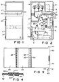
- Figure 1 shows a field of a medium voltage switchgear in a front view.
- FIG. 3 shows an occupational safety plate in an elongated manner Location.
- a detail of the work protection plate according to the figure 3 shows FIG. 4 on an enlarged scale.
- Figure 5 shows an angled guide rail in a Side view.
- Figures 6 and 7 show the cross-sectional shape of the angled Guide rail according to Figure 5 on two different Put.
- a guide cassette for a work protection plate is in the Figure 8 in plan view and in Figure 9 from the side shown.
- the medium-voltage switch panel 1 shown has a housing 2 with a switch room 3, a busbar compartment 4 and a cable connection room 5.
- the switch room 3 is a vacuum circuit breaker movable on rails 6 7, the upper and lower movable isolating contacts 8 and 9 owns.
- the busbar space 4 are feeding busbars 10 arranged with upper fixed isolating contacts 11 are connected.
- Lower fixed isolating contacts 12 are with the interposition of current transformers 13 with Cables 14 connected in a manner not shown are brought down out of the control panel 1.
- Below the current transformer 13 is an earthing switch 15 which grounding of cables 14 allowed when the circuit breaker 7 is in the separation position shown.
- the housing 2 also contains a low-voltage room 16, which is located above the switch room 3 and of the remaining rooms are completely closed off by walls.
- the low-voltage room 16 serves to accommodate Control, protection and display devices for the circuit breaker 7.
- the work protection plate 24 is Part of an occupational health and safety device, to which closer now is received.
- the circuit breaker 7 is in the switch room 3 movably arranged. In this way, the Circuit breaker 7 starting from the disconnected position shown with the protective plate 24 removed into an operating position brought in the upper movable isolating contacts 8 engaged with the opposite fixed Isolating contacts 11 are and the lower movable Isolating contacts 9 with the lower stationary isolating contacts 12. In this state it is ensured in a known manner that the door 21 cannot be opened.
- the circuit breaker 7 is in the in the Figure 2 shown disconnected position, so the connection with the busbars 10 interrupted. It can therefore be in the cable connection compartment 5 can be worked, provided that there is no voltage the cable has also been taken care of.
- Prerequisite for safe Working in the cable connection compartment 5 is, however, a reliable one Protection against contact with the busbars 10 and the lower fixed isolating contacts 12. This protection is manufactured by an occupational safety device, the Structure is explained in more detail below.
- the occupational safety device includes the one already mentioned Protective work plate 24, which is in the extended position in the figure 3 is shown.
- the work protection plate 24 consists of three Sections, of which two sections 25 made of insulating material consist of, while another front section 26 Metal, e.g. Aluminum sheet.
- the three sections are connected by joint pieces 27 made of silicone rubber, the Profile closer to Figure 4 can be seen.
- the Joint piece 27 has a U-profile section for each of the sections 25 30, the edges of the sections tight overlaps. Both U-profile sections 30 are through a web 31 connected, which is only about the thickness of one of the Legs of the U-profile sections 30 and on one Side runs flush with the legs.
- the metal section 26 of the work protection plate According to FIG. 3, 24 has two on its operating side laterally projecting stop lugs 60 and 61, which are in inserted state of the work protection plate against the Create front panel 17 of control panel 1 when the Protective work plate 24 is fully inserted.
- a additionally formed on the stop lug 61 locking lug 62 can reach through an opening in the housing 2. In this position, e.g. depending on the door 20, a locking member in an engagement opening 63 of the locking lug be introduced.
- the work protection device in the control panel 1 includes, in addition to the work protection plate 24 described above, guide means, which in particular consist of a guide cassette 34 accessible on the operating front 17 (FIGS. 1 and 2) and two angled guide rails 35 connected to the latter can be used as left and right unit parts. 5, 6 and 7 show details of the angled guide rails 35.
- Each guide rail 35 comprises five sections, of which a first straight section 36 is provided for attachment to a straight guide rail 37 (FIG. 9) contained in the guide cassette 34.
- the straight section 36 is adjoined by three sections 40, 41 and 42 which are at an angle to one another and which can be regarded as a replica of approximately a quarter-circle arc.
- a fifth section 43 is again straight and lies in a plane parallel to the first section 36.
- the profile of the sections 26, 40, 41 and 42 is in principle similar and corresponds to the symmetrical I-shape shown in FIG. 6 with guide legs 39, on which the guide rail 35 can be used on the left or right side of the housing (FIG. 1 and 2) is based.
- the height w entered in FIG. 6 differs in the individual sections mentioned and decreases in the order in which they are numbered.
- the lowest height h is reached, which only corresponds approximately to the thickness of section 25 of work protection plate 24.
- the lower straight section 43 of the guide rail 35 has the profile shown in FIG. 7. This has grooves 44, into which a partition wall can be inserted, in order to bring about a partial partitioning between the busbar space 4 and the cable connection space 5.
- the guide cassette made of sheet metal 34 forms a channel for pushing the Protective work plate 24.
- the guide cassette has on the front 34 one at the edges in the straight guide rails 38 merging front bar 45 as the lower limit of Insertion opening 23 ( Figure 1).
- a hinge hook 46 is slidable performed, which is biased by a spring 47 so that the Flap 22 is pressed against the front panel.
- the closure flap 22 in a likewise stable open position swiveling.
- a pivotable protective flap 50 which is arranged around an off-center Axis of rotation 51 is pivotable.
- a spring 52 Protective flap 50 biased into the inclined position shown.
- Two rollers 53 attached to the top edge facilitate this Introduce the work protection plate 24 and ensure at the same time the earthing of the first part made of metal 26 ( Figure 4).
- Insert tab 54 and a rear retaining tab 55 are provided.
- the upper edge 56 angled upwards. In the opposite The protruding ends of the straight guide rails make sense 37 angled.
- the mouth width of this arrangement corresponds to that Width w of the angled guide rail 35 achieves that the protective plate 24 is free, i.e. without Contact with the legs of the I-profile of the angled Guide rail 35 can enter the first section 36 and therefore a low resistance to movement without the risk of canting is achieved.
Landscapes
- Engineering & Computer Science (AREA)
- Power Engineering (AREA)
- Patch Boards (AREA)
- Details Of Connecting Devices For Male And Female Coupling (AREA)
- Electrical Discharge Machining, Electrochemical Machining, And Combined Machining (AREA)
- Control Of Electric Motors In General (AREA)
- Control Of Presses (AREA)
- Emergency Protection Circuit Devices (AREA)
- Cable Accessories (AREA)
Claims (11)
- Dispositif de protection du travail pour un tableau (1) électrique de connexion, comportant un appareil (7) qui est monté de manière à pouvoir être entré et sorti et des contacts (11,12) de séparation montés fixe dans le panneau (1) de connexion, ainsi que des contacts (8,9) de séparation mobiles montés sur l'appareil (7), ayant les caractéristiques suivantes:une plaque (24) de protection du travail constituée de pièces (25,26) partielles articulées l'une à l'autre,une ouverture (23) d'introduction de la plaque (24) de protection du travail ménagée sur le panneau (17) frontal de commande du tableau (1) de connexion,des moyens (34,35) de guidage qui font suite à l'ouverture (23) d'introduction, saisissant des branches (39) de guidage montées à distance l'une de l'autre, comprenant des rails (37) de guidage rectilignes, s'étendant à-peu-près sur la hauteur de l'appareil (7), et des rails (35) de guidage coudés, faisant suite aux rails (37) de guidage rectilignes, d'une longueur et d'une conformation telle que la plaque (24) de protection du travail peut être introduite entre les contacts (11,12) de séparation fixe et les contacts (8,9) de séparation mobile, caractérisé par les caractéristiques supplémentaires suivantes:l'articulation des pièces (25,26) partielles de la plaque (24) de protection du travail est formée par une pièce (27) d'articulation en élastomère d'un seul tenant, qui empiète sur les extrémités des pièces (25,26) partielles à relier,la pièce (27) d'articulation a pour chacune des pièces (25,26) partielles à relier un tronçon (30) profilé en forme de U et une barrette (31) continue, formant l'articulation et s'étendant sur toute la largeur des pièces (25,26) partielles.
- Dispositif de protection du travail suivant la revendication 1, caractérisé en ce que l'épaisseur de la barrette (31) ne correspond qu'à une partie de l'épaisseur de la pièce (27) d'articulation et en ce que la barrette (31) devient, d'au moins un côté, par un arrondi (32), les tronçons (30) profilés en U.
- Dispositif de protection du travail suivant la revendication 1 ou 2, caractérisé en ce que la pièce (27) d'articulation est en élasto-silane (caoutchouc ou silicone) et en ce que les tronçons (30) profilés en U sont collés sur une surface aux pièces (25,26) partielles de la plaque (24) de protection du travail.
- Dispositif de protection du travail suivant l'une des revendications précédentes,
caractérisé en ce que la plaque (24) de protection du travail comporte trois pièces (25,26) partielles reliées par des pièces (27) d'articulation et en ce que les rails (35) de guidage coudés comprennent quatre tronçons (36,40,41,42) qui font un angle l'un avec l'autre, de telle manière que l'une (27) des pièces d'articulation se trouvent à proximité de la transition du premier tronçon (27) au deuxième tronçon (40) et que la pièce (27) articulée supplémentaire se trouve dans la zone du troisième tronçon (41). - Dispositif de protection du travail suivant la revendication 4, caractérisé en ce que l'une (26) des pièces (25,26) partielles de la plaque (24) de protection du travail est en métal et a des becs (60,61) de butée en saillie latéralement pour prendre appui sur le panneau (17) frontal de commande du tableau (1) de connexion, l'un (61) des becs de butée comportant un bec (62) de fermeture ayant une ouverture (63) de réception d'un élément de blocage.
- Dispositif de protection du travail suivant la revendication 4, caractérisé en ce que les tronçons (36,40,41,42) du rail (35) de guidage coudé ont un profil symétrique en forme de I ayant une largeur w adaptée aux branches (39) de guidage de manière localisée de sorte que la pièce (25) partielle médiane de la plaque (24) de protection du travail est soutenue par la courbure à la transition du deuxième tronçon (40) du rail (35) de guidage coudé au troisième tronçon (41).
- Dispositif de protection du travail suivant l'une des revendications précédentes, caractérisé en ce que les rails (35) de guidage sont des pièces moulées en matière plastique d'un seul tenant, ayant une profondeur prévue pour la plus grande profondeur d'une série de tableaux (1) de connexion, au moins un repère (49) moulé étant prévu pour la dimension correspondant à un tableau (1) de connexion de profondeur plus petite.
- Dispositif de protection du travail suivant l'une des revendications précédentes, caractérisé en ce que les rails (38) de guidage rectilignes font partie d'une cassette (34) de guidage qui peut être montée dans le tableau (1) de connexion à la suite de l'ouverture (23) d'introduction de la plaque (24) de protection du travail, qui est en tôle d'acier et qui a des articulations (46) à charnières pour un volet (22) de fermeture masquant l'ouverture (23) d'introduction frontale et basculant pour l'ouverture et la fermeture.
- Dispositif de protection du travail suivant la revendication 8, caractérisé en ce que la cassette (34) de guidage contient un volet (50) de protection monté basculant dans la voie de guidage et pouvant être rabattu à l'encontre de la force d'un ressort lors de l'introduction de la plaque (24) de protection du travail.
- Dispositif de protection du travail suivant la revendication 9, caractérisé en ce qu'il est monté sur le volet (50) de protection au moins un galet (53) qui coopère avec la plaque (24) de protection du travail lors de son introduction.
- Dispositif de protection du travail suivant la revendication 8, caractérisé en ce que les rails (37) de guidage rectilignes, contenus dans la cassette (34) de guidage, sont montés, pour soutenir la plaque (24) de protection du travail, de manière à faire saillie par un coude (57) au-dessus de l'ouverture ménagée sur la face arrière de la cassette (34) de guidage et en ce que le bord arrière supérieur de la cassette (34) de guidage a un coude (56) en sens contraire, l'ouverture des coudes (56,57) ayant une dimension correspondant à la largeur w intérieure des branches (39) de guidage des rails de guidage coudés.
Applications Claiming Priority (3)
| Application Number | Priority Date | Filing Date | Title |
|---|---|---|---|
| DE4313652A DE4313652A1 (de) | 1993-04-21 | 1993-04-21 | Arbeitsschutzvorrichtung für ein elektrisches Schaltfeld |
| DE4313652 | 1993-04-21 | ||
| PCT/DE1994/000515 WO1994024744A1 (fr) | 1993-04-21 | 1994-04-19 | Dispositif de protection pour tableaux electriques |
Publications (2)
| Publication Number | Publication Date |
|---|---|
| EP0737377A1 EP0737377A1 (fr) | 1996-10-16 |
| EP0737377B1 true EP0737377B1 (fr) | 1998-06-24 |
Family
ID=6486419
Family Applications (1)
| Application Number | Title | Priority Date | Filing Date |
|---|---|---|---|
| EP94913501A Expired - Lifetime EP0737377B1 (fr) | 1993-04-21 | 1994-04-19 | Dispositif de protection pour tableaux electriques |
Country Status (5)
| Country | Link |
|---|---|
| EP (1) | EP0737377B1 (fr) |
| AT (1) | ATE167761T1 (fr) |
| DE (2) | DE4313652A1 (fr) |
| NO (1) | NO954163L (fr) |
| WO (1) | WO1994024744A1 (fr) |
Families Citing this family (4)
| Publication number | Priority date | Publication date | Assignee | Title |
|---|---|---|---|---|
| DE102006019356A1 (de) * | 2006-04-20 | 2007-10-25 | Siemens Ag | Luftisolierte Mittelspannungs-Schaltanlage |
| US10305262B2 (en) | 2016-09-26 | 2019-05-28 | Bethel Idiculla Johnson | Medium voltage switchgear enclosure |
| USD832222S1 (en) | 2016-09-26 | 2018-10-30 | Switchboard Apparatus, Inc. | Insulator |
| DE102023209516B3 (de) | 2023-09-28 | 2024-11-21 | Siemens Aktiengesellschaft | Verfahren für ein verbessertes Condition Monitoring eines Leistungsschalters, Leistungsschalter und Schaltfeld mit einem solchen Leistungsschalter |
Family Cites Families (3)
| Publication number | Priority date | Publication date | Assignee | Title |
|---|---|---|---|---|
| FR1478398A (fr) * | 1966-01-20 | 1967-04-28 | Merlin Gerin | Dispositif de comande et de verrouillage pour cellules de commutation comprenant un appareil débrochable |
| DE8624915U1 (de) * | 1986-09-18 | 1986-10-30 | Sachsenwerk AG, 8400 Regensburg | Arbeitsschutzvorrichtung für elektrische Schaltanlagen |
| DE9003117U1 (de) * | 1990-03-16 | 1990-05-17 | Elektrotechnische Werke Fritz Driescher & Söhne GmbH & Co, 8052 Moosburg | Isolierende Schutzplatte |
-
1993
- 1993-04-21 DE DE4313652A patent/DE4313652A1/de not_active Withdrawn
-
1994
- 1994-04-19 DE DE59406333T patent/DE59406333D1/de not_active Expired - Fee Related
- 1994-04-19 EP EP94913501A patent/EP0737377B1/fr not_active Expired - Lifetime
- 1994-04-19 AT AT94913501T patent/ATE167761T1/de not_active IP Right Cessation
- 1994-04-19 WO PCT/DE1994/000515 patent/WO1994024744A1/fr not_active Ceased
-
1995
- 1995-10-18 NO NO954163A patent/NO954163L/no unknown
Also Published As
| Publication number | Publication date |
|---|---|
| EP0737377A1 (fr) | 1996-10-16 |
| DE4313652A1 (de) | 1994-10-27 |
| DE59406333D1 (de) | 1998-07-30 |
| WO1994024744A1 (fr) | 1994-10-27 |
| ATE167761T1 (de) | 1998-07-15 |
| NO954163L (no) | 1995-12-21 |
| NO954163D0 (no) | 1995-10-18 |
Similar Documents
| Publication | Publication Date | Title |
|---|---|---|
| DE3639533C2 (fr) | ||
| CH672038A5 (fr) | ||
| DE4130882C1 (fr) | ||
| EP0737377B1 (fr) | Dispositif de protection pour tableaux electriques | |
| WO1996021960A1 (fr) | Cadre de rack a systeme de contacts de coupure | |
| AT403749B (de) | Lastschaltleiste | |
| EP0890971B1 (fr) | Couvercle pour contacts de fusibles dans les dispositifs à fusibles du type basse tension haute puissance | |
| DE8221878U1 (de) | Elektrisch isolierendes Abdeckungselement zum Aufsetzen auf elektrische Leiter | |
| DE2949774B2 (de) | Betätigungs- und Verriegelungsvorrichtung für eine Schaltanlage | |
| DE19531877C2 (de) | Elektrisches Schaltfeld | |
| DE9000374U1 (de) | Gekapselte, trennerlose Schaltanlage | |
| DE19736791C1 (de) | Schaltschrank mit Rahmengestell und Doppeltür | |
| DE9102841U1 (de) | Temperaturschalter mit Schalteinheit und Aufnahmeteil | |
| DE2639640A1 (de) | Elektrische sammelschienenanordnung | |
| DE4233401C1 (en) | Sub-assembly drawer with forward and rearward transverse rails - has rear wall pivoted about lower edge and retained in upright position by catches at top corners behind brackets on sidewall extensions | |
| DE3728796A1 (de) | Klemmenabdeckung fuer ein niederspannungs-schaltgeraet | |
| DE19540334A1 (de) | Kontakttrennvorrichtung eines Abgangskastens eines Energieverteilsystems | |
| DE19641615C2 (de) | Verschlußklappenanordnung | |
| AT397893B (de) | Gekapselte hochspannungs-schaltzelle mit ausfahrbarem trennwagen | |
| DE8624915U1 (de) | Arbeitsschutzvorrichtung für elektrische Schaltanlagen | |
| EP1232509B1 (fr) | Disjoncteur basse tension comportant un boitier presentant une paroi avant et une paroi arriere | |
| DE2246964C3 (de) | Schutzschaltereinrichtung | |
| DE2800277C3 (de) | Hausanschlußkasten mit versetzbarem Einbauteil | |
| DE3243134C2 (fr) | ||
| DE19746935C2 (de) | Abschottungsvorrichtung für Schaltschränke |
Legal Events
| Date | Code | Title | Description |
|---|---|---|---|
| PUAI | Public reference made under article 153(3) epc to a published international application that has entered the european phase |
Free format text: ORIGINAL CODE: 0009012 |
|
| 17P | Request for examination filed |
Effective date: 19951012 |
|
| AK | Designated contracting states |
Kind code of ref document: A1 Designated state(s): AT DE |
|
| 17Q | First examination report despatched |
Effective date: 19970214 |
|
| GRAG | Despatch of communication of intention to grant |
Free format text: ORIGINAL CODE: EPIDOS AGRA |
|
| GRAG | Despatch of communication of intention to grant |
Free format text: ORIGINAL CODE: EPIDOS AGRA |
|
| GRAH | Despatch of communication of intention to grant a patent |
Free format text: ORIGINAL CODE: EPIDOS IGRA |
|
| GRAH | Despatch of communication of intention to grant a patent |
Free format text: ORIGINAL CODE: EPIDOS IGRA |
|
| GRAA | (expected) grant |
Free format text: ORIGINAL CODE: 0009210 |
|
| AK | Designated contracting states |
Kind code of ref document: B1 Designated state(s): AT DE |
|
| REF | Corresponds to: |
Ref document number: 167761 Country of ref document: AT Date of ref document: 19980715 Kind code of ref document: T |
|
| REF | Corresponds to: |
Ref document number: 59406333 Country of ref document: DE Date of ref document: 19980730 |
|
| PLBE | No opposition filed within time limit |
Free format text: ORIGINAL CODE: 0009261 |
|
| STAA | Information on the status of an ep patent application or granted ep patent |
Free format text: STATUS: NO OPPOSITION FILED WITHIN TIME LIMIT |
|
| 26N | No opposition filed | ||
| PGFP | Annual fee paid to national office [announced via postgrant information from national office to epo] |
Ref country code: AT Payment date: 20020313 Year of fee payment: 9 |
|
| PG25 | Lapsed in a contracting state [announced via postgrant information from national office to epo] |
Ref country code: AT Free format text: LAPSE BECAUSE OF NON-PAYMENT OF DUE FEES Effective date: 20030419 |
|
| PGFP | Annual fee paid to national office [announced via postgrant information from national office to epo] |
Ref country code: DE Payment date: 20040621 Year of fee payment: 11 |
|
| PG25 | Lapsed in a contracting state [announced via postgrant information from national office to epo] |
Ref country code: DE Free format text: LAPSE BECAUSE OF NON-PAYMENT OF DUE FEES Effective date: 20051101 |