EP0737776B1 - Pressvorrichtung für eine Papiermaschine oder dergleichen - Google Patents
Pressvorrichtung für eine Papiermaschine oder dergleichen Download PDFInfo
- Publication number
- EP0737776B1 EP0737776B1 EP96101384A EP96101384A EP0737776B1 EP 0737776 B1 EP0737776 B1 EP 0737776B1 EP 96101384 A EP96101384 A EP 96101384A EP 96101384 A EP96101384 A EP 96101384A EP 0737776 B1 EP0737776 B1 EP 0737776B1
- Authority
- EP
- European Patent Office
- Prior art keywords
- press
- press shoe
- shoe
- sleeve
- accordance
- Prior art date
- Legal status (The legal status is an assumption and is not a legal conclusion. Google has not performed a legal analysis and makes no representation as to the accuracy of the status listed.)
- Expired - Lifetime
Links
Images

Classifications
-
- D—TEXTILES; PAPER
- D21—PAPER-MAKING; PRODUCTION OF CELLULOSE
- D21F—PAPER-MAKING MACHINES; METHODS OF PRODUCING PAPER THEREON
- D21F3/00—Press section of machines for making continuous webs of paper
- D21F3/02—Wet presses
- D21F3/0209—Wet presses with extended press nip
- D21F3/0218—Shoe presses
Definitions
- the invention relates to a press device for a paper machine or the like, comprising a shoe press roll a stationary support body on which a press shoe radially is slidably mounted, the hydraulically to a counter roller is pressed, and with return means for withdrawing the Press shoe from the counter roll.
- the known pressing device is a Long nip press device with a shoe press roll, which is hydraulic can be pressed against a counter roller.
- the shoe press roll has a press shoe on a in the longitudinal direction of the press shoe running pressure chamber hydraulically to the counter roller can be pressed.
- the pressure chamber is from the press shoe and a shoe bed formed on a stationary support body the shoe press roll supports. Runs over the press shoe in a known manner, a press jacket, which is used to minimize the Friction on the press shoe is hydrodynamically lubricated.
- This construction is intended to achieve a design that is as flat as possible be to the dimensions of the shoe press unit, especially the Increase the size of the shoe bed in the radial direction to have to.
- a similar pressing device is from DE 41 13 623 C1 known in the spring elements also within the pressure chamber are arranged, the prevailing in the pressure chamber Counteract pressure to enter with an almost unpressurized pressure chamber Pull the press shoe back towards the shoe bed to reach.
- a disadvantage of such an assembly is that appropriate bushings are required, that require additional seals and that in addition holes are required in the support body, what with a corresponding Weakening of the supporting body is connected.
- the press shoe is therefore provided not to press through a single elongated pressure chamber, but instead a plurality of in the longitudinal direction of the Press shoe's hydraulic cylinder / piston units lined up to use so that the contact pressure of the press shoe adapted to the necessary conditions over its longitudinal direction can be.
- Spring elements are located within the cylinder / piston units provided to press the respective cylinder / piston unit to the press shoe even when the pressure chamber is depressurized ensure that even with insufficient pressure in the pressure chamber a clean contact of the sealing surfaces of the Cylinder / piston unit on the press shoe is guaranteed so that lateral leakage of hydraulic oil is avoided.
- the Cylinder / piston units can be tilted by a certain amount arranged to allow application to the press shoe.
- the known press device thus allows a sensitive Regulation of the pressure along the length of the press shoe, however, no measures have been taken to retracting the press shoe against the action of Ensure spring force in the direction of the supporting body.
- no measures have been taken to retracting the press shoe against the action of Ensure spring force in the direction of the supporting body.
- the maximum stroke of the piston / cylinder units is limited. Especially when the shoe press roll is arranged at the top, however, this is often not sufficient, especially for Starting up the paper machine and during maintenance and adjustment work.
- a pressing device of a similar type is known from EP 0 345 501 B1 known, but with the same disadvantages as the previous one has described pressing device.
- the invention is therefore based on the object of a pressing device to improve in accordance with the type mentioned at the beginning, that allows easy assembly and disassembly of the press shoe is and that the lowest possible weakening of the support body caused by the return means.
- the object is achieved in that at a Press device of the type mentioned in the longitudinal direction of the press shoe a plurality of hydraulic elements for pressing the press shoe is provided on the counter roller, and that the Return means outside the hydraulic elements on the support body and attack the press shoe.
- the contact pressure of the press shoe to the counter roll in the direction of the longitudinal extent of the press shoe to the necessary conditions can be adjusted if, for example, a reduction in Press pressure especially in the edge areas with narrower Paper webs than is normally required.
- the return means spring elements that are substantially vertical arranged parallel to the hydraulic elements to the press shoe are.
- the return means also as Hydraulic elements or other structures could be the use of spring elements is particularly preferred since as a result, the structure of the return means is particularly simple designed.
- the spring elements in the axial direction of the spring elements extend extending tie rods, the press shoe facing ends via hinge connections with the press shoe are connectable.
- clamping elements for tensioning the spring elements during assembly or at a Replacement of the press shoe provided.
- the Clamping elements off-center on the mounts of the coil springs on.
- lateral guide rails for receiving in the direction of web travel provided transverse forces acting on the press shoe.
- the guide rails supporting the press shoe consist of individual guide pieces in the longitudinal direction of the press shoe are spaced from each other.
- At least one hydraulic element one with hydraulic pressure pressurizable pressure chamber between the support body and the press shoe is formed in a cylindrical recess, and which is laterally delimited by a first sleeve which in the cylindrical recess is axially displaceable and tiltable is led.
- the first sleeve can be directly in the cylindrical bore be led. In an alternative version, however, you can use a second sleeve interact telescopically.
- the first sleeve versus a second in the cylindrical Recess on the support body by means of a sleeve Seal guided axially movable and tiltable.
- first Sleeve arranged within the second sleeve and the pressure means is designed as a compression spring within the first Sleeve preferably between an end face of the cylindrical Recess and a projection of the first sleeve is arranged.
- the second sleeve is within the first Sleeve arranged, and the pressure means designed as a compression spring is preferably between an outer projection second sleeve and an end face of the cylindrical recess arranged.
- a sleeve is generally sufficient which together with the press shoe within the cylindrical Recess is movable.
- the first sleeve - As already mentioned - also telescopic with a second sleeve interact that either inside or outside the first sleeve is arranged.
- this can preferably designed as a spiral spring pressure element either inside the pressure room or outside the pressure room in the Recess be arranged.
- the recess is preferably a cylindrical recess educated. However, instead of several consecutively arranged cylindrical recesses also within the support body a groove extending in the direction of the press shoe is provided be in which several hydraulic elements are accommodated.
- a pressing device is shown in Fig. 1 and designated overall by the number 10.
- the press device comprises a shoe press roll 12 with a hydraulic to a Counter roll 14 pressable press shoe 26, via which a tubular Press jacket 18 rotates, being in the area between the Press shoe 26 and the counter roll 14 formed a press nip 16 is.
- the shoe press roll 12 has a stationary support body 24 with a series of circumferentially arranged guide strips 19 on which the tubular press jacket 18th can be guided outside the press nip 16. Usually runs he is contactless at a short distance from the guide rails 19th
- the press shoe 26 has a concave in a known manner Cross section on which is adapted to the shape of the counter roller 14 and is shaped accordingly on the inlet side of the paper web is to get a good education of a hydrodynamic Lube wedge when the press jacket 18 rotates through the press nip 16 ensure in the web running direction 28 of the paper web 20.
- Fig. 1 shows an arrangement in which the shoe press roll 12th is arranged above the counter roller 14. It goes without saying that the invention of course also in the reverse arrangement is advantageously used, in which the shoe press roll below is arranged.
- FIG. 1 is a first inner sleeve 80 on the end face by means of a sealing ring 84 against the contact surface 93 of the press shoe 26 sealed.
- An outer sleeve (or "Cylinder") 81 which surrounds the inner sleeve 80, is rigid connected to the support body 24 (e.g. by means of a not shown Screws). It is facing away from the press shoe 26 End face by means of an O-ring 92 against the end face 83 of the cylindrical recess 88 sealed and is at her the press shoe 26 facing end on the inside by a sealed radially against the inner sleeve 80 sealing ring 82.
- the first sleeve 80 is by means of a pressure means 90, the arranged as a coil spring within the first sleeve 80 is pressed against the contact surface 93 of the press shoe 26, wherein the spring 90 rests on an annular web 86 of the sleeve 80.
- first, inner sleeve 80 which is connected to the second, outer Sleeve cooperates, the end face 83 of the cylindrical Expansion 88 and the contact surface 93 of the press shoe 26 a pressure chamber bounded with the hydraulic channel Pressure can be applied. Since the first sleeve 80 to the contact surface 93 of the press shoe 26 is open and only opposite this is sealed, on the one hand there is mechanical wear avoided between the hydraulic element and the press shoe 26. On the other hand, horizontal relative movements between the Hydraulic element 30 and the press shoe tolerated, which e.g. by Thermal expansion or due to changes in load on the press shoe 26 could be. There is also a tilt in the guide of the sleeves 80, 81 avoided.
- the pressure means 90 in the form of the spring achieves that in all operating conditions (even if in the hydraulic element 30 there is no hydraulic pressure), the inner sleeve 80 clean rests on the press shoe 26, so that a lateral escape of Hydraulic oil is avoided.
- Fig. 1 there is none Hydraulic pressure available, so that the press shoe 26 under the Effect of return means 32, 34 (see below) on the support body 24 is present. If there is hydraulic pressure, then it rises the press shoe 26 from the support body 24; then he "swims" to a certain extent on that limited by the hydraulic element 30 Pressure pad and is only on the side via guide rails 74 guided, which the transverse forces occurring during operation record, tape.
- the sleeve 80 can be inside the second sleeve 81 tilt to a certain extent to make appropriate movements to be able to follow the press shoe 26.
- the return means 32, 34 are on both sides of the press shoe 26 attacking spring elements 36, 38 in the form of coil springs formed at their ends facing away from the press shoe 26 60, 62 rest on so-called spring plates 40, 42.
- the spring plate 40, 42 are screwed in the middle with tie rods 56 and 58, down through the coil springs by appropriate Recesses 64, 66 of the support body 24 up to the press shoe 26 extend and connected to this on the side surfaces are.
- the spring elements are between the spring plates 40 or 42 and contact surfaces 41 or 43 of the support body 24 clamped. A lowering of the press shoe 26 leads downward thus to a correspondingly increased tension of the spring elements 36, 38.
- clamping elements 44, 46 provided on the central support body by means of holders 52, 54 are fastened and by means of clamping screws 48 and 50 against the spring plate 40 or 42 are clamped. Grab it the clamping screws 48 or 50 off-center on the spring plates 40 or 42 so that when tightening the clamping screws 48 or 50 the coil springs 36 and 38 with their spring plates 40 or 42 and also with the associated tie rods 56 or 58 away from the side surfaces of the press shoe 26 be printed so that loosening and removal of the press shoe 26 is facilitated during disassembly.
- the recesses 64 and 66 in the support body 24 have a appropriate width, so that a certain tilt of the Tie rods 56 and 58 to the outside, in each case away from the press shoe 26, is possible.
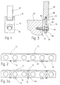
- the fork 108 is by means of a quick connector 78 to attach to the press shoe 26.
- the quick connector 78 has a circular opening 110 in the fork 108, through which the head of a screw 96 is passed can.
- the screw 96 is in a threaded bore 102 in the Side surface 104 of the press shoe 26 is screwed in and lies there with a collar 98 on the side surface 104 of the press shoe 26 on. Between the head of the screw 96 and the collar 98 is a Neck 100 provided with a reduced diameter. The screw 96 can thus, when the head is aligned with the opening 110, inserted through this until the neck of the screw 100 reaches the area of the opening 110.
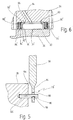
- FIG. 5 An alternative embodiment of the connection between strut 58 and the press shoe 26 is shown in FIG. 5.
- the striker 116 points at its outer end a groove 118 with which this in the Opening 110 'of the extension 114 can be hung.
- the spring force should be sufficient, at least the spring force of the pressure means 90 and the weight of the press shoe 26 to compensate for further emergence of the Press shoe 26 from the shoe press roll 12 in the assembly or Prevent maintenance.
- the spring force should be as possible the coil springs 36, 38 should be dimensioned somewhat more so that the press shoe 26 with a certain force to the support body 24 is withdrawn.
- the side guide rails which consist of individual Guide pieces 74 are used to accommodate the in the direction of ban 28 acting transverse force.
- the opposite guide pieces 72 only serve to guide the press shoe 26 the opposite side, but they don't have to be larger Take up lateral forces.
- the guide strips are on both sides of the press shoe 26 in the area of the return means 32 or 34 interrupted, so that the individual guide pieces 72 and 74 arise.
- relatively large hydraulic elements 30, which in a single Row, smaller hydraulic elements 30a, which are in two rows are provided.
- the number is arbitrary; she can be larger or smaller than shown in Fig. 2a.
- FIG. 6 shows an alternative construction of a hydraulic element 30 'shown.
Landscapes
- Paper (AREA)
- Fluid-Pressure Circuits (AREA)
- Actuator (AREA)
Description
- Fig. 1
- einen Querschnitt durch eine erfindungsgemäße Preßvorrichtung in vereinfachter Darstellung, wobei lediglich wichtige Teile der Schuhpreßwalze dargestellt sind und die Gegenwalze nur angedeutet ist;
- Fig. 2
- eine Aufsicht auf einen erfindungsgemäßen Preßschuh, bei der lediglich die Lage der Hydraulikelemente, der Rückholmittel und der Führungsstücke vereinfacht dargestellt ist;
- Fig. 2a
- eine Abwandlung der Ausführung gemäß Fig. 2;
- Fig. 3
- einen vergrößerten Ausschnitt aus Fig. 1 in geschnittener Darstellung, aus der Aufbau der Gelenkverbindung und des Schnell-Verbindungselementes erkennbar ist;
- Fig. 4
- eine Ansicht der Verbindung gemäß Fig. 3;
- Fig. 5
- eine alternative Ausführung der Verbindung des Federelementes mit dem Preßschuh; und
- Fig. 6
- einen alternativen Aufbau eines erfindungsgemäßen Hydraulikelementes.
Claims (14)
- Preßvorrichtung für eine Papiermaschine oder dgl., mit einer Schuhpreßwalze (12), umfassend einen stationären Tragkörper (24), an dem ein Preßschuh (26) radial verschieblich gelagert ist, der hydraulisch an eine Gegenwalze (14) anpreßbar ist, und mit Rückholmitteln (32, 34) zum Zurückziehen des Preßschuhs (26) von der Gegenwalze (14), dadurch gekennzeichnet, daß in Längsrichtung des Preßschuhs (26) eine Mehrzahl von Hydraulikelementen (30) zum Anpressen des Preßschuhs (26) an die Gegenwalze (14) vorgesehen ist, und daß die Rückholmittel (32, 34) außerhalb der Hydraulikelemente (30) am Tragkörper (24) und am Preßschuh (26) angreifen.
- Preßvorrichtung nach Anspruch 1, dadurch gekennzeichnet, daß die Rückholmittel (32, 34) Federelemente (36, 38) aufweisen, die im wesentlichen senkrecht zum Preßschuh (26) parallel zu den Hydraulikelementen (30) angeordnet sind.
- Preßvorrichtung nach Anspruch 2, dadurch gekennzeichnet, daß die Federelemente (36, 38) in bezug auf den Preßschuh (26) kippbar angeordnet sind.
- Preßvorrichtung nach Anspruch 2 oder 3, dadurch gekennzeichnet, daß die Federelemente (36, 38) in Axialrichtung der Federelemente (36, 38) verlaufende Zuganker (56, 58) umfassen, deren dem Preßschuh (26) zugewandte Enden über Gelenkverbindungen (68, 70) mit dem Preßschuh (26) verbindbar sind.
- Preßvorrichtung nach einem oder mehreren der Ansprüche 2 bis 4, dadurch gekennzeichnet, daß die Federelemente (36, 38) als Schraubenfedern ausgebildet sind, deren dem Preßschuh abgewandte Enden (60, 62) in Federtellern (40, 42) gehalten sind, die über die Zuganker (56, 58) mit dem Preßschuh (26) verbunden sind.
- Preßvorrichtung nach einem oder mehreren der Ansprüche 2 bis 5, dadurch gekennzeichnet, daß Spannelemente (44, 46) zum Spannen der Federelemente (36, 38) bei der Montage vorgesehen sind.
- Preßvorrichtung nach Anspruch 6, dadurch gekennzeichnet, daß die Spannelemente (44, 46) außermittig an den Aufnahmen (40, 42) der Schraubenfedern (36, 38) angreifen.
- Preßvorrichtung nach einem oder mehreren der vorhergehenden Ansprüche, dadurch gekennzeichnet, daß die Zuganker (56, 58) über Schnell-Verbindungselemente (76, 78, 78') mit den Seitenflächen (104) des Preßschuhs (26) verbindbar sind, die jeweils ein seitlich aus dem Preßschuh hervorstehendes Element (96, 116) umfassen, das in einen Fortsatz der Zuganker (56, 58) einhängbar ist.
- Preßvorrichtung nach einem oder mehreren der vorhergehenden Ansprüche, dadurch gekennzeichnet, daß seitliche Führungsleisten zur Aufnahme von in Umfangsrichtung der Preßwalze (12) wirkenden Querkräften vorgesehen sind, über die der Preßschuh (26) abgestützt ist, wobei die Führungsleisten aus einzelnen Führungsstücken (72, 74) bestehen, die in Längsrichtung des Preßschuhs (26) voneinander beabstandet angeordnet sind.
- Preßvorrichtung nach einem oder mehreren der vorhergehenden Ansprüche, dadurch gekennzeichnet, daß wenigstens ein Hydraulikelement (30) eine mit hydraulischem Druck beaufschlagbare Druckkammer umfaßt, die zwischen dem Tragkörper (24) und dem Preßschuh (26) in einer Ausnehmung (79, 79') gebildet ist, und die seitlich von einer ersten Hülse (80, 80') begrenzt ist, die in der Ausnehmung (79, 79') axial verschieblich und kippbar geführt ist.
- Preßvorrichtung nach Anspruch 10, dadurch gekennzeichnet, daß die Hülse (80, 80') mittels eines Andruckmittels (90, 90') gegen eine Anlagefläche (93) des Preßschuhs (26) beaufschlagt ist.
- Preßvorrichtung nach Anspruch 10 oder 11, dadurch gekennzeichnet, daß die erste Hülse (80, 80') gegenüber einer zweiten, in der Ausnehmung (79, 79') am Tragkörper (24) festgelegten Hülse (81, 81') mittels einer Dichtung (82, 82') axial beweglich und verkippbar geführt ist.
- Preßvorrichtung nach Anspruch 12, dadurch gekennzeichnet, daß die erste Hülse (80) innerhalb der zweiten Hülse (81) angeordnet ist, und daß das Andruckmittel (90) eine Druckfeder ist, durch die die erste Hülse (80) gegen den Preßschuh (26) beaufschlagt ist.
- Preßvorrichtung nach Anspruch 12, dadurch gekennzeichnet, daß die zweite Hülse (81') innerhalb der ersten Hülse (80') angeordnet ist, und daß das Andruckmittel (90') eine Druckfeder ist, durch die die zweite Hülse (81') gegen den Preßschuh (26) beaufschlagt ist.
Applications Claiming Priority (2)
| Application Number | Priority Date | Filing Date | Title |
|---|---|---|---|
| DE19514142 | 1995-04-15 | ||
| DE19514142A DE19514142C1 (de) | 1995-04-15 | 1995-04-15 | Preßvorrichtung für eine Papiermaschine |
Publications (2)
| Publication Number | Publication Date |
|---|---|
| EP0737776A1 EP0737776A1 (de) | 1996-10-16 |
| EP0737776B1 true EP0737776B1 (de) | 1998-10-14 |
Family
ID=7759712
Family Applications (1)
| Application Number | Title | Priority Date | Filing Date |
|---|---|---|---|
| EP96101384A Expired - Lifetime EP0737776B1 (de) | 1995-04-15 | 1996-02-01 | Pressvorrichtung für eine Papiermaschine oder dergleichen |
Country Status (7)
| Country | Link |
|---|---|
| US (1) | US5662777A (de) |
| EP (1) | EP0737776B1 (de) |
| JP (1) | JP3795566B2 (de) |
| AT (1) | ATE172259T1 (de) |
| CA (1) | CA2173778C (de) |
| DE (1) | DE19514142C1 (de) |
| FI (1) | FI113067B (de) |
Cited By (1)
| Publication number | Priority date | Publication date | Assignee | Title |
|---|---|---|---|---|
| EP2278066A2 (de) | 2009-07-21 | 2011-01-26 | Andritz Küsters GmbH | Schuhwalze |
Families Citing this family (23)
| Publication number | Priority date | Publication date | Assignee | Title |
|---|---|---|---|---|
| DE19603652C2 (de) * | 1996-02-01 | 2000-06-21 | Voith Sulzer Papiermasch Gmbh | Durchbiegungseinstellwalze |
| DE19615226A1 (de) * | 1996-04-18 | 1997-10-23 | Voith Sulzer Papiermasch Gmbh | Trockenpartie |
| US5897747A (en) * | 1997-08-08 | 1999-04-27 | Beloit Technologies, Inc. | Machine direction profiling of extended nip press shoe |
| US6017422A (en) * | 1997-09-30 | 2000-01-25 | Valmet-Karlstad Ab | Shoe press |
| SE510553C2 (sv) * | 1997-09-30 | 1999-05-31 | Valmet Karlstad Ab | Skopress för en pappers- eller kartongmaskin |
| US6093283A (en) * | 1997-09-30 | 2000-07-25 | Valmet-Karlstad Ab | Shoe press and method for supporting a press shoe in a shoe press |
| US6547924B2 (en) | 1998-03-20 | 2003-04-15 | Metso Paper Karlstad Ab | Paper machine for and method of manufacturing textured soft paper |
| US5882483A (en) * | 1998-06-10 | 1999-03-16 | Beloit Technologies, Inc. | Extended nip press apparatus |
| US6517683B2 (en) * | 2000-05-29 | 2003-02-11 | Metso Paper Karlstad Ab | Shoe press with movable guides to alter machine direction shoe position |
| US6610173B1 (en) | 2000-11-03 | 2003-08-26 | Kimberly-Clark Worldwide, Inc. | Three-dimensional tissue and methods for making the same |
| DE10351294A1 (de) * | 2003-10-31 | 2005-06-02 | Voith Paper Patent Gmbh | Anpresseinrichtung |
| FI116854B (fi) | 2004-02-19 | 2006-03-15 | Vaahto Oy | Menetelmä ja laitteisto kenkäpuristimen yhteydessä |
| FI118088B (fi) | 2004-02-19 | 2007-06-29 | Vaahto Oy | Kenkäpuristimen kuormituslaite |
| DE102006003888A1 (de) * | 2006-01-27 | 2007-08-02 | Voith Patent Gmbh | Schuhpresswalze |
| DE102006021428A1 (de) * | 2006-05-05 | 2007-11-08 | Andritz Küsters GmbH & Co. KG | Vorrichtung zum Bilden mindestens eines Langspalts |
| SE536202C2 (sv) | 2011-07-12 | 2013-06-25 | Metso Paper Sweden Ab | Förfarande och maskin för tillverkning av en strukturerad fiberbana av papper |
| SE538098C2 (sv) | 2013-11-14 | 2016-03-01 | Valmet Aktiebolag | En långnypsvals med ett stödelement för behandling av en fiberbana |
| SE542841C2 (en) | 2018-04-19 | 2020-07-14 | Valmet Oy | Method and a machine for producing a tissue web |
| SE542214C2 (en) | 2018-10-12 | 2020-03-10 | Valmet Oy | A tissue paper making machine and a method of operating a tissue paper making machine |
| FI12247U1 (fi) * | 2018-10-12 | 2018-12-14 | Valmet Technologies Oy | Sovitelma kuiturainakoneen hihnatelassa |
| DE102019119905A1 (de) * | 2019-07-23 | 2021-01-28 | Voith Patent Gmbh | Schuhpresse |
| DE102019119894A1 (de) * | 2019-07-23 | 2021-01-28 | Voith Patent Gmbh | Presseneinheit |
| CN112522984B (zh) * | 2020-12-17 | 2022-06-07 | 淄博泰鼎机械科技有限公司 | 一种靴式压榨机 |
Family Cites Families (4)
| Publication number | Priority date | Publication date | Assignee | Title |
|---|---|---|---|---|
| SE461171C (sv) * | 1988-05-25 | 1992-08-17 | Valmet Paper Machinery Inc | Press med laangt nyp foer pappers- eller kartongmaskiner |
| DE4113623C1 (de) * | 1991-04-26 | 1992-02-20 | J.M. Voith Gmbh, 7920 Heidenheim, De | |
| DE4319323A1 (de) * | 1993-06-11 | 1993-11-04 | Voith Gmbh J M | Verfahren zum betreiben einer pressenpartie und vorrichtung zum durchfuehren des verfahrens |
| DE4402595C2 (de) * | 1994-01-28 | 1995-08-03 | Voith Gmbh J M | Langspaltpreßeinrichtung |
-
1995
- 1995-04-15 DE DE19514142A patent/DE19514142C1/de not_active Expired - Lifetime
-
1996
- 1996-02-01 EP EP96101384A patent/EP0737776B1/de not_active Expired - Lifetime
- 1996-02-01 AT AT96101384T patent/ATE172259T1/de not_active IP Right Cessation
- 1996-02-23 JP JP03691596A patent/JP3795566B2/ja not_active Expired - Fee Related
- 1996-02-27 FI FI960906A patent/FI113067B/fi not_active IP Right Cessation
- 1996-04-05 US US08/628,470 patent/US5662777A/en not_active Expired - Lifetime
- 1996-04-10 CA CA002173778A patent/CA2173778C/en not_active Expired - Fee Related
Cited By (2)
| Publication number | Priority date | Publication date | Assignee | Title |
|---|---|---|---|---|
| EP2278066A2 (de) | 2009-07-21 | 2011-01-26 | Andritz Küsters GmbH | Schuhwalze |
| DE102009033933A1 (de) | 2009-07-21 | 2011-01-27 | Andritz Küsters Gmbh | Schuhwalze |
Also Published As
| Publication number | Publication date |
|---|---|
| FI960906A0 (fi) | 1996-02-27 |
| EP0737776A1 (de) | 1996-10-16 |
| US5662777A (en) | 1997-09-02 |
| ATE172259T1 (de) | 1998-10-15 |
| DE19514142C1 (de) | 1996-07-11 |
| FI113067B (fi) | 2004-02-27 |
| JP3795566B2 (ja) | 2006-07-12 |
| FI960906A7 (fi) | 1996-10-16 |
| JPH08291492A (ja) | 1996-11-05 |
| CA2173778C (en) | 2007-08-07 |
| CA2173778A1 (en) | 1996-10-16 |
Similar Documents
| Publication | Publication Date | Title |
|---|---|---|
| EP0737776B1 (de) | Pressvorrichtung für eine Papiermaschine oder dergleichen | |
| DE3124915C2 (de) | Druckmittelzylinder mit einem längsgeschlitzten endseitig verschlossenen Zylinderrohr | |
| DE3325305C2 (de) | Pressenrahmen | |
| AT399174B (de) | Langspaltpresse, insbesondere zum entwässern einer faserstoffbahn | |
| DE3802703A1 (de) | Kolbenstangenlose zylinderanordnung | |
| DE2759035B2 (de) | Hydraulisches Stützelement | |
| DE3317455A1 (de) | Presseinrichtung, insbesondere zum entwaessern einer papierbahn | |
| EP0060498B1 (de) | Vorrichtung zum Verbinden von zwei stumpf gestossenen Bewehrungsstäben mittels einer Muffe | |
| DE3238264C2 (de) | ||
| DE2830733B2 (de) | Vorrichtung zum schnellen Trennen der Walzen eines Kalanders | |
| DE4415645A1 (de) | Walze für eine Papiermaschine | |
| EP0803606B1 (de) | Durchbiegungsausgleichswalze | |
| DE69604874T2 (de) | Stützvorrichtung für die Seitenwände einer Walzenstranggiessanlage zum Herstellen metallischer Bänder | |
| DE4009627A1 (de) | Leiste zur nachgiebigen stuetzung eines siebbandes | |
| DE4024716A1 (de) | Druckmittelzylinder mit laengsgeschlitztem zylinderrohr | |
| DE2853050C2 (de) | Seitliche Abdichtungsvorrichtung für einen Ausbaurahmen im untertägigen Bergbau | |
| DE3637108A1 (de) | Pressenwalze, die insbesondere zur behandlung einer papierbahn oder dergleichen dient | |
| EP2294261B1 (de) | Leistenanordnung für eine maschine zur herstellung einer faserstoffbahn | |
| AT3188U1 (de) | Schuhpresse | |
| DE2718414C2 (de) | Dichtungsanordnung an einer Walze | |
| DE10313444A1 (de) | Vorrichtung, bei der ein erster Zylinder und ein an diesen angestellter zweiter Zylinder einen Spalt bilden | |
| DE3204358A1 (de) | Vorrichtung zur endlagendaempfung der bewegung eines kolbens mit zugehoeriger kolbenstange und weiter komponenten in einem hydraulischen zylinder | |
| DE2841372A1 (de) | Bremsbacke | |
| DE2852420C2 (de) | Futterwürfelpresse | |
| DE4127776C2 (de) | Klammerverschluß eines Reaktordeckels |
Legal Events
| Date | Code | Title | Description |
|---|---|---|---|
| PUAI | Public reference made under article 153(3) epc to a published international application that has entered the european phase |
Free format text: ORIGINAL CODE: 0009012 |
|
| 17P | Request for examination filed |
Effective date: 19960201 |
|
| AK | Designated contracting states |
Kind code of ref document: A1 Designated state(s): AT IT SE |
|
| GRAG | Despatch of communication of intention to grant |
Free format text: ORIGINAL CODE: EPIDOS AGRA |
|
| GRAG | Despatch of communication of intention to grant |
Free format text: ORIGINAL CODE: EPIDOS AGRA |
|
| GRAH | Despatch of communication of intention to grant a patent |
Free format text: ORIGINAL CODE: EPIDOS IGRA |
|
| 17Q | First examination report despatched |
Effective date: 19980326 |
|
| GRAH | Despatch of communication of intention to grant a patent |
Free format text: ORIGINAL CODE: EPIDOS IGRA |
|
| GRAA | (expected) grant |
Free format text: ORIGINAL CODE: 0009210 |
|
| AK | Designated contracting states |
Kind code of ref document: B1 Designated state(s): AT IT SE |
|
| REF | Corresponds to: |
Ref document number: 172259 Country of ref document: AT Date of ref document: 19981015 Kind code of ref document: T |
|
| RAP2 | Party data changed (patent owner data changed or rights of a patent transferred) |
Owner name: VOITH SULZER PAPIERTECHNIK PATENT GMBH |
|
| PLBQ | Unpublished change to opponent data |
Free format text: ORIGINAL CODE: EPIDOS OPPO |
|
| PLBI | Opposition filed |
Free format text: ORIGINAL CODE: 0009260 |
|
| PLBF | Reply of patent proprietor to notice(s) of opposition |
Free format text: ORIGINAL CODE: EPIDOS OBSO |
|
| 26 | Opposition filed |
Opponent name: VALMET-KARLSTAD AB Effective date: 19990714 |
|
| PLBF | Reply of patent proprietor to notice(s) of opposition |
Free format text: ORIGINAL CODE: EPIDOS OBSO |
|
| PLBL | Opposition procedure terminated |
Free format text: ORIGINAL CODE: EPIDOS OPPC |
|
| PLBP | Opposition withdrawn |
Free format text: ORIGINAL CODE: 0009264 |
|
| PLBM | Termination of opposition procedure: date of legal effect published |
Free format text: ORIGINAL CODE: 0009276 |
|
| STAA | Information on the status of an ep patent application or granted ep patent |
Free format text: STATUS: OPPOSITION PROCEDURE CLOSED |
|
| 27C | Opposition proceedings terminated |
Effective date: 20020301 |
|
| PGFP | Annual fee paid to national office [announced via postgrant information from national office to epo] |
Ref country code: AT Payment date: 20100212 Year of fee payment: 15 |
|
| PGFP | Annual fee paid to national office [announced via postgrant information from national office to epo] |
Ref country code: SE Payment date: 20110214 Year of fee payment: 16 |
|
| PG25 | Lapsed in a contracting state [announced via postgrant information from national office to epo] |
Ref country code: AT Free format text: LAPSE BECAUSE OF NON-PAYMENT OF DUE FEES Effective date: 20110201 |
|
| PGFP | Annual fee paid to national office [announced via postgrant information from national office to epo] |
Ref country code: IT Payment date: 20120224 Year of fee payment: 17 |
|
| PG25 | Lapsed in a contracting state [announced via postgrant information from national office to epo] |
Ref country code: SE Free format text: LAPSE BECAUSE OF NON-PAYMENT OF DUE FEES Effective date: 20120202 |
|
| PG25 | Lapsed in a contracting state [announced via postgrant information from national office to epo] |
Ref country code: IT Free format text: LAPSE BECAUSE OF NON-PAYMENT OF DUE FEES Effective date: 20140201 |