EP0737991A1 - Elektrisches Gerät, insbesondere Leistungsschalter, ausgerüstet mit einer Sicherheitsvorrichtung - Google Patents
Elektrisches Gerät, insbesondere Leistungsschalter, ausgerüstet mit einer Sicherheitsvorrichtung Download PDFInfo
- Publication number
- EP0737991A1 EP0737991A1 EP96410025A EP96410025A EP0737991A1 EP 0737991 A1 EP0737991 A1 EP 0737991A1 EP 96410025 A EP96410025 A EP 96410025A EP 96410025 A EP96410025 A EP 96410025A EP 0737991 A1 EP0737991 A1 EP 0737991A1
- Authority
- EP
- European Patent Office
- Prior art keywords
- contacts
- stop
- opening
- lever
- position corresponding
- Prior art date
- Legal status (The legal status is an assumption and is not a legal conclusion. Google has not performed a legal analysis and makes no representation as to the accuracy of the status listed.)
- Granted
Links
- 238000006073 displacement reaction Methods 0.000 claims description 2
- 238000003466 welding Methods 0.000 claims description 2
- 239000007787 solid Substances 0.000 abstract 3
- 240000008042 Zea mays Species 0.000 description 3
- 230000000694 effects Effects 0.000 description 2
- 238000007789 sealing Methods 0.000 description 2
- 230000006835 compression Effects 0.000 description 1
- 238000007906 compression Methods 0.000 description 1
- 230000008878 coupling Effects 0.000 description 1
- 238000010168 coupling process Methods 0.000 description 1
- 238000005859 coupling reaction Methods 0.000 description 1
- 230000006866 deterioration Effects 0.000 description 1
- 238000012986 modification Methods 0.000 description 1
- 230000004048 modification Effects 0.000 description 1
Images

Classifications
-
- H—ELECTRICITY
- H01—ELECTRIC ELEMENTS
- H01H—ELECTRIC SWITCHES; RELAYS; SELECTORS; EMERGENCY PROTECTIVE DEVICES
- H01H71/00—Details of the protective switches or relays covered by groups H01H73/00 - H01H83/00
- H01H71/10—Operating or release mechanisms
- H01H71/50—Manual reset mechanisms which may be also used for manual release
- H01H71/501—Means for breaking welded contacts; Indicating contact welding or other malfunction of the circuit breaker
-
- H—ELECTRICITY
- H01—ELECTRIC ELEMENTS
- H01H—ELECTRIC SWITCHES; RELAYS; SELECTORS; EMERGENCY PROTECTIVE DEVICES
- H01H9/00—Details of switching devices, not covered by groups H01H1/00 - H01H7/00
- H01H9/20—Interlocking, locking, or latching mechanisms
- H01H9/28—Interlocking, locking, or latching mechanisms for locking switch parts by a key or equivalent removable member
- H01H2009/288—Provisions relating to welded contacts
-
- H—ELECTRICITY
- H01—ELECTRIC ELEMENTS
- H01H—ELECTRIC SWITCHES; RELAYS; SELECTORS; EMERGENCY PROTECTIVE DEVICES
- H01H9/00—Details of switching devices, not covered by groups H01H1/00 - H01H7/00
- H01H9/20—Interlocking, locking, or latching mechanisms
- H01H9/28—Interlocking, locking, or latching mechanisms for locking switch parts by a key or equivalent removable member
- H01H9/281—Interlocking, locking, or latching mechanisms for locking switch parts by a key or equivalent removable member making use of a padlock
Definitions
- the present invention relates to an electrical device, and in particular a circuit breaker equipped with a safety device, this device being arranged to prevent padlocking in the event of welding of a movable contact on a fixed contact following a short circuit, this device being equipped with a manual control lever arranged to be brought by rotation about an axis, either in a normal open position corresponding to the opening of said contacts, or in a normal closed position corresponding to the closing of said contacts , and a control mechanism which transmits control of said lever to a pivoting arm carrying said movable contact.
- the present invention aims to eliminate this danger by equipping the electrical appliance concerned with an adequate safety device.
- the electrical device according to the invention characterized in that the safety device comprises a stop serving as a stop for said control lever, this stop being offset angularly, relative to a position corresponding to the position. normal opening, of an angle sufficient for the force applied to this lever to bring it to bear against this stop is greater than or equal to a predetermined threshold when said contacts are welded.
- said predetermined threshold corresponds to a breaking force of essential components of the apparatus, and said breaking force is defined by a standard.
- the drum carrying the control handle has a recess which is arranged to coincide with an opening formed in the side walls of a housing of the device, to allow said padlocking, said opening is angularly offset with respect to the position occupied by said recess when the lever is in the position corresponding to the application of a force whose value is equivalent to said predetermined threshold when said contacts are welded.
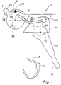
- the partially shown device in this case a circuit breaker 10, comprises a pair of contacts, one of which 11 is fixed and mounted on a support 12 which is connected, in a non- shown, at one of the terminals of the circuit breaker and the other of which 13 is movable.
- This movable contact is arranged at one end of an arm 14 pivoting about an axis 15, called a movable contact arm.
- the axis 15 is mounted on a plate 16 which also carries a hooking hook 17 articulated on an axis 18 integral with the plate 16.
- the hooking hook is linked to one end of a link 19, this end being articulated at a point 20 on said hook, the other end of the link 19 being articulated at a point 21 on a drum 22 rotating around an axis 23 which carries a lever 24 for manual control.
- the drum 22 is housed in an appropriate cavity of the circuit breaker housing and has a recess 25 which, when the contacts are open and the lever is brought into abutment against a stop integral with said housing, coincides with an opening 27 formed through the side walls of this housing to allow the passage of a sealing wire 28, the handle of a padlock or other locking device.
- the configuration of the components as shown in FIG. 1 corresponds to a normal situation, the contacts being free, not welded, and the lever with manual control acting through the control mechanism, correctly on the movable contact.
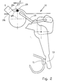
- FIG. 2 shows this same device 10 when the contacts 11 and 13 are soldered following a short circuit. It can be seen that, although the contacts are closed, the handle 24 for manual control has been able to be brought to bear against the stop 26 and that the recess 25 has been brought opposite the opening 27 made in the side walls of the housing so that the lockout operation was made possible. To reach this state, the operator had to force the lever, which has the effect of deforming the link 19.
- the applied force is less than a limit value, or threshold defined by a standard. Beyond this threshold, the applied force causes a complete rupture of the mechanism but, below this threshold, the applied force causes only a deformation of the link which does not allow the operator to realize danger due to the non-de-energization of the circuit.
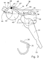
- the device 30 shown in this case a circuit breaker, comprises as before a fixed contact 31 mounted on a support 32, a movable contact 33 disposed at one end of an arm 34 pivoting around an axis 35.
- This axis is carried by a plate 36 which also carries a hook 37 articulated on an axis 38 integral with this plate.
- a link 39 is linked at a point 40 to said hook 37 and at a point 41 to a drum 42, rotatable about an axis 43, which carries a lever 44 for manual control.
- the drum 42 is provided with a recess 45 which, when the contacts 31 and 33 are open and the lever is brought into abutment against a stop 46 secured to the housing (not shown) of the device, coincides with an opening 47 formed through the side walls of this box to allow the passage of a sealing wire 48 or the handle of a padlock.
- the configuration of the components as shown in FIG. 3 corresponds to a normal situation, the contacts 31 and 33 being free, not welded, and the manual control lever 44 acting correctly on the movable contact, through the control mechanism.
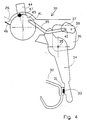
- FIG. 4 shows the device 30 in a configuration where the contacts 31 and 33 are soldered following a short circuit.
- the handle 44 is in an intermediate position without deformation of the link 39.
- the recess 45 does not coincide with the opening 47, so that a padlocking of the device is not possible.
- the device When the operator exerts a force on the lever 44 in the opening direction, the device can be brought into a position which corresponds to that of FIG. 5.
- the configuration shown corresponds to a limit force, or threshold normalized in below which the mechanism is not completely destroyed, and beyond which the essential components of the mechanism are damaged. It is noted that, in this case, the manual control lever 44 is not in abutment against the stop 46 and that the recess 45 does not coincide with the opening 47 so that padlocking of the device does not is not possible. If the operator pushes the joystick by applying a force which is greater than said threshold, deterioration of essential components of the apparatus is inevitable.
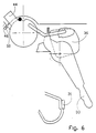
- Figure 6 shows the device in the unlocked open position, following normal triggering. Note that the recess does not coincide with the opening 47, preventing padlocking. The latter is only possible if the lever 44 is pressed against the stop 46.
- FIG. 6 it is possible to provide a compression spring 50 which is mounted in such a way that it tends to oppose the movement of the lever 44 in its final phase, that is to say towards the support against the stop 46, when the contacts 31 and 33 are free.
- the spring 50 opposes a determined resistance on the lever in the displacement phase in which the contacts are already open, but where the lockout position is not yet reached. This resistance makes it possible to make the user attentive to his approach by forcing him to press his effort on the joystick.
- the spring could be replaced by a friction, or any other member having the same functions, making it possible to attract the attention of the user.
Landscapes
- Breakers (AREA)
- Emergency Protection Circuit Devices (AREA)
- Braking Systems And Boosters (AREA)
- Braking Arrangements (AREA)
- Switch Cases, Indication, And Locking (AREA)
- Driving Mechanisms And Operating Circuits Of Arc-Extinguishing High-Tension Switches (AREA)
Applications Claiming Priority (2)
| Application Number | Priority Date | Filing Date | Title |
|---|---|---|---|
| FR9504679A FR2733087B1 (fr) | 1995-04-13 | 1995-04-13 | Appareil electrique et notamment disjoncteur equipe d'un dispositif de securite |
| FR9504679 | 1995-04-13 |
Publications (2)
| Publication Number | Publication Date |
|---|---|
| EP0737991A1 true EP0737991A1 (de) | 1996-10-16 |
| EP0737991B1 EP0737991B1 (de) | 2002-06-12 |
Family
ID=9478253
Family Applications (1)
| Application Number | Title | Priority Date | Filing Date |
|---|---|---|---|
| EP96410025A Expired - Lifetime EP0737991B1 (de) | 1995-04-13 | 1996-03-19 | Elektrisches Gerät, insbesondere Leistungsschalter, ausgerüstet mit einer Sicherheitsvorrichtung |
Country Status (7)
| Country | Link |
|---|---|
| EP (1) | EP0737991B1 (de) |
| CN (1) | CN1056705C (de) |
| AT (1) | ATE219282T1 (de) |
| DE (1) | DE69621695T2 (de) |
| ES (1) | ES2176422T3 (de) |
| FR (1) | FR2733087B1 (de) |
| HU (1) | HU218957B (de) |
Cited By (1)
| Publication number | Priority date | Publication date | Assignee | Title |
|---|---|---|---|---|
| EP1143477A1 (de) * | 2000-04-07 | 2001-10-10 | Hager Electro S.A. | Sicherheitseinrichtung für elektrisches Gerät vom Schutzschalter Typ |
Families Citing this family (3)
| Publication number | Priority date | Publication date | Assignee | Title |
|---|---|---|---|---|
| EP1111644B1 (de) * | 1999-12-21 | 2004-03-24 | Hager Electro S.A. | Sicherheitsvorrichtung für elektrisches Gerät |
| DE102010020987B4 (de) | 2010-05-19 | 2012-04-05 | Eaton Industries Gmbh | Leistungsschalter mit Abschließvorrichtung |
| KR102007779B1 (ko) * | 2018-02-06 | 2019-08-07 | 엘에스산전 주식회사 | 접지스위치를 갖는 개폐장치 |
Citations (2)
| Publication number | Priority date | Publication date | Assignee | Title |
|---|---|---|---|---|
| EP0408466A2 (de) * | 1989-07-11 | 1991-01-16 | Merlin Gerin | Betätigungsmechanismus für elektrischen Schalter |
| EP0450699A2 (de) * | 1990-04-04 | 1991-10-09 | GE Power Controls Italia S.p.a. | Abschliessvorrichtung mittels Vorhängeschloss von Handbedienteilen elektromechanischer Einrichtungen |
-
1995
- 1995-04-13 FR FR9504679A patent/FR2733087B1/fr not_active Expired - Fee Related
-
1996
- 1996-03-19 ES ES96410025T patent/ES2176422T3/es not_active Expired - Lifetime
- 1996-03-19 AT AT96410025T patent/ATE219282T1/de not_active IP Right Cessation
- 1996-03-19 DE DE69621695T patent/DE69621695T2/de not_active Expired - Fee Related
- 1996-03-19 EP EP96410025A patent/EP0737991B1/de not_active Expired - Lifetime
- 1996-04-11 HU HU9600942A patent/HU218957B/hu not_active IP Right Cessation
- 1996-04-13 CN CN96105766A patent/CN1056705C/zh not_active Expired - Fee Related
Patent Citations (2)
| Publication number | Priority date | Publication date | Assignee | Title |
|---|---|---|---|---|
| EP0408466A2 (de) * | 1989-07-11 | 1991-01-16 | Merlin Gerin | Betätigungsmechanismus für elektrischen Schalter |
| EP0450699A2 (de) * | 1990-04-04 | 1991-10-09 | GE Power Controls Italia S.p.a. | Abschliessvorrichtung mittels Vorhängeschloss von Handbedienteilen elektromechanischer Einrichtungen |
Cited By (1)
| Publication number | Priority date | Publication date | Assignee | Title |
|---|---|---|---|---|
| EP1143477A1 (de) * | 2000-04-07 | 2001-10-10 | Hager Electro S.A. | Sicherheitseinrichtung für elektrisches Gerät vom Schutzschalter Typ |
Also Published As
| Publication number | Publication date |
|---|---|
| FR2733087A1 (fr) | 1996-10-18 |
| CN1056705C (zh) | 2000-09-20 |
| CN1139287A (zh) | 1997-01-01 |
| HU9600942D0 (en) | 1996-06-28 |
| EP0737991B1 (de) | 2002-06-12 |
| HU218957B (hu) | 2001-01-29 |
| HUP9600942A3 (en) | 1999-04-28 |
| ATE219282T1 (de) | 2002-06-15 |
| FR2733087B1 (fr) | 1997-06-06 |
| DE69621695T2 (de) | 2002-12-05 |
| ES2176422T3 (es) | 2002-12-01 |
| HUP9600942A2 (en) | 1997-05-28 |
| DE69621695D1 (de) | 2002-07-18 |
Similar Documents
| Publication | Publication Date | Title |
|---|---|---|
| EP0610143B1 (de) | Mechanische und elektrische Verriegelungsvorrichtung einer Fernbedienungseinheit für modulare Lastschalter | |
| FR2631485A1 (fr) | Mecanisme de commande de disjoncteur miniature a indicateur de soudure des contacts | |
| EP0766280A2 (de) | Befehls- und Meldegerät für Schutzschalter | |
| FR2863403A1 (fr) | Dispositif de signalisation du declenchement d'un appareil de protection electrique et appareil de protection electrique le comportant | |
| EP0161946B1 (de) | An einen Schutzschalter ankuppelbare Zusatzeinheit | |
| EP0737991B1 (de) | Elektrisches Gerät, insbesondere Leistungsschalter, ausgerüstet mit einer Sicherheitsvorrichtung | |
| EP0547928B1 (de) | Schutzschalter | |
| EP0669633B1 (de) | Schutzschaltgerät | |
| EP2377139B1 (de) | Vorrichtung zur fernbetätigung und damit versehener schutzschalter | |
| EP2717284B1 (de) | Bedienungsvorrichtung eines elektrischen Schutzschaltgeräts, und diese umfassendes elektrisches Schutzschaltgerät | |
| EP0580464B1 (de) | Sperrvorrichtung für Gehäuse und Machine mit einer solchen Vorrichtung | |
| EP0311668A1 (de) | Schutzschaltgerät mit vereinfachtem auslösemechanismus | |
| FR2503930A1 (fr) | Declencheur a minimum de tension pour disjoncteurs de puissance | |
| EP3249673B1 (de) | Vorrichtung zur signalisierung einer elektrischen störung in einem elektrischen schutzgerät, und elektrisches schutzgerät, das eine solche vorrichtung umfasst | |
| EP0461027B1 (de) | Differential Auslösevorrichtung | |
| EP3657522B1 (de) | Betätigungsmechanismus zum öffnen und schliessen einer stromunterbrechungsvorrichtung für einen elektrichen schalter | |
| FR2940517A1 (fr) | Dispositif de telecommande pourvu de moyens de signalisation et disjoncteur telecommande equipe d'un tel dispositif de telecommande | |
| EP3309813B1 (de) | Elektrischer differenzialschutzschalter, der eine testvorrichtung für die differenzialfunktion umfasst | |
| FR2940515A1 (fr) | Dispositif de telecommande et disjoncteur telecommande equipe d'un tel dispositif | |
| EP0736945B1 (de) | Trenner-Begrenzungs-Schutz für dreiphasige elektrische Transformatoren | |
| EP0897188B1 (de) | Steuervorrichtung für elektrischer Schutzapparat wie ein Schutzschalter mit einer Anzeigevorrichtung zur Auslösung, und Schutzschalter ausgerüstet mit einer solchen Vorrichtung | |
| EP0218497B1 (de) | Schutzschalter mit federnder Lasche | |
| EP0393566B1 (de) | Elektrischer Schutzschalter | |
| EP2642502B1 (de) | Auslöseblock für elektrisches Sicherungsgerät, und mit einem solchen Block ausgestattetes elektrisches Sicherungsgerät | |
| FR2770614A1 (fr) | Dispositif de commande fermeture d'un clapet comportant un boitier servant de support aux divers composants constitutifs du dispositif |
Legal Events
| Date | Code | Title | Description |
|---|---|---|---|
| PUAI | Public reference made under article 153(3) epc to a published international application that has entered the european phase |
Free format text: ORIGINAL CODE: 0009012 |
|
| AK | Designated contracting states |
Kind code of ref document: A1 Designated state(s): AT BE CH DE ES GB IT LI NL SE |
|
| 17P | Request for examination filed |
Effective date: 19970313 |
|
| RAP1 | Party data changed (applicant data changed or rights of an application transferred) |
Owner name: SCHNEIDER ELECTRIC INDUSTRIES SA |
|
| RAP1 | Party data changed (applicant data changed or rights of an application transferred) |
Owner name: SCHNEIDER ELECTRIC INDUSTRIES SA |
|
| 17Q | First examination report despatched |
Effective date: 20000922 |
|
| GRAG | Despatch of communication of intention to grant |
Free format text: ORIGINAL CODE: EPIDOS AGRA |
|
| GRAG | Despatch of communication of intention to grant |
Free format text: ORIGINAL CODE: EPIDOS AGRA |
|
| GRAH | Despatch of communication of intention to grant a patent |
Free format text: ORIGINAL CODE: EPIDOS IGRA |
|
| GRAH | Despatch of communication of intention to grant a patent |
Free format text: ORIGINAL CODE: EPIDOS IGRA |
|
| GRAA | (expected) grant |
Free format text: ORIGINAL CODE: 0009210 |
|
| AK | Designated contracting states |
Kind code of ref document: B1 Designated state(s): AT BE CH DE ES GB IT LI NL SE |
|
| REF | Corresponds to: |
Ref document number: 219282 Country of ref document: AT Date of ref document: 20020615 Kind code of ref document: T |
|
| REG | Reference to a national code |
Ref country code: GB Ref legal event code: FG4D Free format text: NOT ENGLISH |
|
| REG | Reference to a national code |
Ref country code: CH Ref legal event code: EP |
|
| REF | Corresponds to: |
Ref document number: 69621695 Country of ref document: DE Date of ref document: 20020718 |
|
| GBT | Gb: translation of ep patent filed (gb section 77(6)(a)/1977) |
Effective date: 20020806 |
|
| RAP2 | Party data changed (patent owner data changed or rights of a patent transferred) |
Owner name: SCHNEIDER ELECTRIC INDUSTRIES SAS |
|
| NLT1 | Nl: modifications of names registered in virtue of documents presented to the patent office pursuant to art. 16 a, paragraph 1 |
Owner name: SCHNEIDER ELECTRIC INDUSTRIES SAS |
|
| NLT2 | Nl: modifications (of names), taken from the european patent patent bulletin |
Owner name: SCHNEIDER ELECTRIC INDUSTRIES SAS |
|
| REG | Reference to a national code |
Ref country code: ES Ref legal event code: FG2A Ref document number: 2176422 Country of ref document: ES Kind code of ref document: T3 |
|
| PG25 | Lapsed in a contracting state [announced via postgrant information from national office to epo] |
Ref country code: GB Free format text: LAPSE BECAUSE OF NON-PAYMENT OF DUE FEES Effective date: 20030319 Ref country code: AT Free format text: LAPSE BECAUSE OF NON-PAYMENT OF DUE FEES Effective date: 20030319 |
|
| PG25 | Lapsed in a contracting state [announced via postgrant information from national office to epo] |
Ref country code: SE Free format text: LAPSE BECAUSE OF NON-PAYMENT OF DUE FEES Effective date: 20030320 Ref country code: ES Free format text: LAPSE BECAUSE OF NON-PAYMENT OF DUE FEES Effective date: 20030320 |
|
| PG25 | Lapsed in a contracting state [announced via postgrant information from national office to epo] |
Ref country code: LI Free format text: LAPSE BECAUSE OF NON-PAYMENT OF DUE FEES Effective date: 20030331 Ref country code: CH Free format text: LAPSE BECAUSE OF NON-PAYMENT OF DUE FEES Effective date: 20030331 Ref country code: BE Free format text: LAPSE BECAUSE OF NON-PAYMENT OF DUE FEES Effective date: 20030331 |
|
| PLBE | No opposition filed within time limit |
Free format text: ORIGINAL CODE: 0009261 |
|
| STAA | Information on the status of an ep patent application or granted ep patent |
Free format text: STATUS: NO OPPOSITION FILED WITHIN TIME LIMIT |
|
| 26N | No opposition filed |
Effective date: 20030313 |
|
| BERE | Be: lapsed |
Owner name: S.A. *SCHNEIDER ELECTRIC INDUSTRIES Effective date: 20030331 |
|
| PG25 | Lapsed in a contracting state [announced via postgrant information from national office to epo] |
Ref country code: NL Free format text: LAPSE BECAUSE OF NON-PAYMENT OF DUE FEES Effective date: 20031001 Ref country code: DE Free format text: LAPSE BECAUSE OF NON-PAYMENT OF DUE FEES Effective date: 20031001 |
|
| EUG | Se: european patent has lapsed | ||
| GBPC | Gb: european patent ceased through non-payment of renewal fee |
Effective date: 20030319 |
|
| REG | Reference to a national code |
Ref country code: CH Ref legal event code: PL |
|
| NLV4 | Nl: lapsed or anulled due to non-payment of the annual fee |
Effective date: 20031001 |
|
| REG | Reference to a national code |
Ref country code: ES Ref legal event code: FD2A Effective date: 20030320 |
|
| PG25 | Lapsed in a contracting state [announced via postgrant information from national office to epo] |
Ref country code: IT Free format text: LAPSE BECAUSE OF NON-PAYMENT OF DUE FEES Effective date: 20050319 |