EP0738048A2 - Equipement d'abboné et procédé pour réaliser et exploiter un réseau numérique de communication - Google Patents
Equipement d'abboné et procédé pour réaliser et exploiter un réseau numérique de communication Download PDFInfo
- Publication number
- EP0738048A2 EP0738048A2 EP19960105678 EP96105678A EP0738048A2 EP 0738048 A2 EP0738048 A2 EP 0738048A2 EP 19960105678 EP19960105678 EP 19960105678 EP 96105678 A EP96105678 A EP 96105678A EP 0738048 A2 EP0738048 A2 EP 0738048A2
- Authority
- EP
- European Patent Office
- Prior art keywords
- processor
- transmission
- subscriber device
- subscriber
- branch
- Prior art date
- Legal status (The legal status is an assumption and is not a legal conclusion. Google has not performed a legal analysis and makes no representation as to the accuracy of the status listed.)
- Withdrawn
Links
- 238000000034 method Methods 0.000 title claims abstract description 15
- 238000004891 communication Methods 0.000 title claims description 10
- 230000005540 biological transmission Effects 0.000 claims abstract description 102
- 238000007906 compression Methods 0.000 claims abstract description 6
- 230000006835 compression Effects 0.000 claims abstract description 6
- 238000012360 testing method Methods 0.000 claims abstract description 5
- 230000006837 decompression Effects 0.000 claims abstract 2
- 238000012545 processing Methods 0.000 claims description 19
- 238000005516 engineering process Methods 0.000 claims description 11
- 238000005259 measurement Methods 0.000 claims description 5
- 238000001514 detection method Methods 0.000 claims description 4
- 238000006243 chemical reaction Methods 0.000 claims description 3
- 230000002457 bidirectional effect Effects 0.000 claims 2
- 238000013144 data compression Methods 0.000 claims 1
- 238000007781 pre-processing Methods 0.000 claims 1
- 238000012546 transfer Methods 0.000 claims 1
- 230000008569 process Effects 0.000 abstract description 5
- 238000010276 construction Methods 0.000 description 6
- 238000010586 diagram Methods 0.000 description 3
- 230000006978 adaptation Effects 0.000 description 2
- 238000001914 filtration Methods 0.000 description 2
- 238000002372 labelling Methods 0.000 description 2
- 230000003321 amplification Effects 0.000 description 1
- 230000004069 differentiation Effects 0.000 description 1
- 230000003993 interaction Effects 0.000 description 1
- 230000000873 masking effect Effects 0.000 description 1
- 230000007246 mechanism Effects 0.000 description 1
- 238000012544 monitoring process Methods 0.000 description 1
- 238000003199 nucleic acid amplification method Methods 0.000 description 1
- 230000010355 oscillation Effects 0.000 description 1
- 230000009467 reduction Effects 0.000 description 1
- 230000002787 reinforcement Effects 0.000 description 1
- 238000005070 sampling Methods 0.000 description 1
- 230000001629 suppression Effects 0.000 description 1
- 230000001052 transient effect Effects 0.000 description 1
- 230000001960 triggered effect Effects 0.000 description 1
- XLYOFNOQVPJJNP-UHFFFAOYSA-N water Substances O XLYOFNOQVPJJNP-UHFFFAOYSA-N 0.000 description 1
Images




Classifications
-
- H—ELECTRICITY
- H04—ELECTRIC COMMUNICATION TECHNIQUE
- H04M—TELEPHONIC COMMUNICATION
- H04M9/00—Arrangements for interconnection not involving centralised switching
- H04M9/02—Arrangements for interconnection not involving centralised switching involving a common line for all parties
- H04M9/022—Multiplex systems
- H04M9/027—Frequency division multiplex systems
Definitions
- the invention relates to a subscriber device and an associated method for setting up and operating a digital communication network with a plurality of similar subscriber devices.
- the invention is based on the object of offering a subscriber facility and associated methods and possible uses by means of which any number of subscribers can establish transmission or reception connections without using central switching units.
- Claim 34 represents an advantageous use claim.
- the subscriber device according to the invention and the digital communication network formed from a plurality of subscriber devices enable simultaneous communication of several subscribers and the targeted establishment of a point-to-point connection between two or more subscribers and the masking out of certain subscribers.
- Each subscriber continuously sends or receives messages and data blocks via its subscriber device.
- the messages sent by other subscriber devices are stored in the memory unit connected to the subscriber device of each subscriber, so that after a transmission cycle in which each active subscriber has sent exactly once, the storage unit of each subscriber device is occupied with the respective messages or data sent by certain other active subscriber devices.
- the respective individual storage unit connected to each subscriber device is thus supplied with data for storage during the course of each transmission cycle.
- the memory allocation within the memory unit takes place according to an identifier previously assigned to the individual subscribers and subscriber devices.
- the subscriber device In the course of each transmission cycle, the subscriber device according to the invention successively queries the other subscriber devices known by the identifier and, if appropriate, receives data information to be stored in the storage unit.
- each active subscriber device has the opportunity to send data to the other subscriber devices at least once within a transmission cycle.
- Each transmission cycle thus contains reception sections, transmission sections of its own subscriber device and a section in which a request to send to a previously unknown subscriber device is issued.
- max. Provide a new, previously unknown subscriber device with an identifier and include it in the circle of active subscribers - which is to be included in the following transmission cycle.
- each participant device is equipped with a specific delay mechanism, which sends the transmission messages - with respect to other subscriber facilities - with different specific delay times. This ensures that the subscriber device that sends its transmission message in front of another subscriber device, which has not yet been recorded, is newly recorded in the course of a transmission cycle.
- individual new subscriber devices are added to the group of active subscribers successively in successive transmission cycles in the order that results from their assigned delay time.
- the individual subscriber devices are coupled to one another via the same transmission medium (e.g. radio connection, infrared connection).
- the same transmission medium e.g. radio connection, infrared connection.
- the electromagnetic waves of all subscriber devices are transmitted or received on an identical frequency.
- a particularly advantageous use of the subscriber device according to the invention is the use of the subscriber device for automatic sensor-controlled information transmission. While the transmission messages are normally spoken by the users of the subscriber devices into the subscriber device, such automatic information transmission is triggered, for example, by a sensor (e.g. accident sensor, crash sensor), whereupon the respective subscriber device sends a message to all the other subscriber devices and sends them ahead, for example warns of an accident or sends any other - predetermined - message.
- the subscriber device according to the invention is therefore also suitable for carrying out monitoring and control work. In the event of sudden changes in status that lead to the triggering of a sensor, the respective sensor-related information message (e.g. warning accident !, warning flooding !, warning fire! Etc.) is then passed on to the other participant facilities.
- Such automatically exchanged messages can serve for information, warning, routine query, etc. of the other subscriber devices.
- FIG. 1 The interaction of the individual block elements of the subscriber device according to the invention is shown in FIG. 1.
- a control processor 6 can be seen, which is in control connection with an I / O processor 1, a protocol processor 2, a signal processing processor 3, a time slice processor 4 and a transmission device 5.
- the I / O processor 1 is shown, which has a microphone input 7, a loudspeaker output 8, a CD input 35 and an AUX input 36.
- modem inputs and other data transmission inputs are not shown.
- FIG. 1 also shows the antenna 42 connected to the transmission device 5, which is used for transmitting or receiving electromagnetic waves in the case of a radio connection with other subscriber devices. If the subscriber devices are connected via infrared signals, infrared receiving elements 56 or transmitting elements 57 are used.
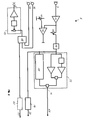
- the circuit diagram according to FIG. 2 shows an insight into the I / O processor 1.
- the microphone input 7 is connected to the input amplifier 11, at the output of which there is a comparator 12 with an actuating element 45.
- Input amplifier 11 and comparator 12 are used to detect the presence of a headset.
- the output of the input amplifier 11 is also connected to the volume control 13 and the subsequent antialias filter 14.
- the anti-alias filter 14 has a bandpass filter for suppressing unwanted background noise and is connected to elements for level measurement 33, which in turn contain an additional bandpass filter for special speech recognition.
- the anti-aliasing filter 14 is connected to a signal detection element 10 which is associated with the elements for level measurement 33 and which is a Differentiation between useful and interference signals (e.g.
- a VOX signal 15 switches through the elements for level measurement 33 and the anti-alias filter 14 via the connection 62 to the control processor.
- the antialias filter 14 and the signal detection element 10 are connected to the signal processing processor 3 via the A / D converter 16 via the connection 24.
- the I / O processor 1 furthermore has a connection 23 to the signal processing processor 3, which opens via a D / A converter 63 into a mixing stage 18, at which the CD input 35 and the AUX input 36 are also connected of I / O processor 1 are connected.
- a loudspeaker output stage 17 with a loudspeaker output 8 which enables tone control, individual volume adjustment and volume adjustment depending on the ambient volume.
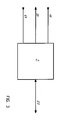
- the protocol processor 2 can furthermore have one or more sensor inputs 64, via which the automatic transmission of transmission messages described in claim 30 can take place.
- sensor input 64 A wide variety of sensors can be connected to such a sensor input 64 (crash sensors, temperature sensors, water level sensors, pressure sensors etc.), so that the subscriber device according to the invention can also be used to control and monitor sensor sizes and associated apparatus.
- FIG. 4 shows the signal processing processor 3 according to FIG. 1 with connections 23, 24 to or from the I / O processor 1 and protocol processor 2.
- the compression processor 25 is used for compressing or decompressing data for the purpose of data reduction or data expansion.
- the test element 38 is attached to the compression processor 25 for data protection (for example by forming checksums) connected.
- the test element 38 is connected to the time slice processor 4 according to FIG. 1 via the connection 34.
- FIG. 5 shows the structure of a time slice processor 4 according to FIG. 1.
- the time slice processor 4 receives signals from the transmission device 5 via a connection 37 for the selection device 26, which contains reception time slices 27 which are assigned the identifiers of the other subscriber devices.
- the individual reception time slices 27 are then queried successively and the messages that may have been received are forwarded from other subscriber devices via the connection 34 to the signal processing processor 3.
- the time slice processor 4 receives data for the selection device 28 via the connection 34 from the signal processing processor 3, which data contains individual transmission time slices 40, each of which is provided with the identifier of the other known subscriber devices.
- the data is then sent via the connection 37 to the transmission device 5 while leaving the selection device 28.
- the selection device 26 and the selection device 28 are controlled in a coordinating manner by means of a management element 41 connected to the control processor as part of each transmission cycle.
- the management element 41 can, for example, also recognize signals from a new subscriber device that occur with a new identifier and, for example, set up a new reception time slice 27 or transmission time slice 40 or, in the opposite case, delete it.
- the management element 41 can be used to query a code for filtering out certain subscribers using the PIN number.
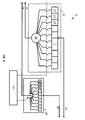
- FIG. 6 shows a first embodiment of the transmission device 5 according to FIG. 1 with connections 37 to the time slice processor 4.
- the transmission device 5 according to FIG. 6 is implemented in high-frequency technology and has a central synthesizer 29 which is connected to the transmission branch 47 and via mixers 54 and 55 is connected to the receiving branch 48.
- the transmission branch 47 has a further synthesizer 49, the intermediate transmission frequency 50 of which is a multiple, in particular twice (or half, a third, a quarter, not shown) of the intermediate reception frequency 51 of the reception branch 48.
- the further synthesizer 49 has a divider 52 which can be switched on / off (or multiplier with filter elements, not shown) connected.
- the intermediate transmission frequency 50 which is identical to the intermediate reception frequency 51, can be selected.
- the other components can be found in the labeling according to FIG. 6.
- the further synthesizer 49 can be switched on and off as required via the divider 52, so that it is ensured that, for example, the otherwise disruptive transmission frequency is not important when receiving at the reception frequency, the frequency of the further synthesizer 49 is exactly a multiple, in the present case If the double, namely 142 MHz instead of 71 MHz of the reception frequency 51, is.
- the further synthesizer 49 can oscillate without disturbing the reception process and does not have to be switched on again and again while accepting undesired transient processes.
- FIG. 7 shows a second embodiment of the transmission device 5 according to FIG. 1, likewise in high-frequency technology with connections 37 to the time slice processor 4.
- a transmission branch 47 and a reception branch 48 which are likewise supplied via a central synthesizer 29, which is fed in via mixers 54 and 55 will be served.
- An NCO 53 (numercially controlled oscillator) is provided in the transmission branch 47, which mixes signals coming from the time slice processor 4 - after division into an I and Q component - with an oscillation signal.
- the NCO 53 can be switched on and off without delay, so that there is complete freedom from interference during the reception process in the reception branch 48 due to the switched off NCO 53.
- the other tasks of the components can be found in the figure labeling according to FIG. 7.
- 6 and 7 therefore show two transmission devices 5 which are designed using high-frequency technology and in which the precautions described avoid mutual interference between the transmission and reception processes.
- 6 and 7 operate via radio signals and use an antenna 42 as the transmission or reception medium.
- FIG. 8 shows a transmission device 5 which is implemented in infrared technology and which works without carrier frequency technology.
- a receiving branch 48 with an infrared receiving element 56 and a transmitting branch 47 with an infrared transmitting element 57 are provided.
- the transmission device 5 according to FIG. 8 has the components identified in the circuit diagram and also contains a conversion element 65 (for example a Schmitt trigger) in the receiving branch 48, with which sinusoidal signals are converted into square-wave signals.
- a conversion element 65 for example a Schmitt trigger
- FIG. 9 shows a further embodiment of a transmission device 5 using infarrot technology with the aid of carrier frequency technology.
- a transmission branch 47 and a reception branch 48 as well as connections 37 to the time slice processor 4.
- Either an NCO 58 or 60 or a synthesizer 59 is used to generate the transmission or reception frequency.
- FIG. 10 shows a transmission device 5 with analog GMSK modulators 67 or GMSK demodulators 68.
- the analog GMSK modulator 67 generates the "eye-pattern" signal 70 by filtering, which passes through the low-pass filter 76 for interference signal suppression and then through a frequency or phase-modulated synthesizer 69.
- the latter can have a multiple or a fraction of that between the reception frequency 51 and can be connected to the mixer 54 by a corresponding divider 52 or multiplier (not shown) (cf. also FIG. 6).
- the modulatable synthesizer 69 can also have an intermediate transmission frequency 50 which corresponds to the intermediate reception frequency 51.
- corresponding switches 66 would then have to be inserted, and mixers 54 that could be switched on / off and an output stage 73 that could be switched on and off would be used (not shown).
- the demodulator 71 (preferably designed as a coincidence demodulator) recovers the “eye pattern” signal 70 which passes through the amplification / adaptation stage 77 (with offset adaptation) and a low-pass filter 78 that suppresses interference signals then enters the analog GMSK demodulator 68.
- the analog transmission device 5 according to FIG. 10 has a considerably lower power consumption compared to a digital system.
- the transmission branch 47 can be operated in "C mode" with high efficiency and only low demands on the distortion freedom of mixer 54 and output stage 73.
- FIG. 11 shows a transmission device 5 with a synthesizer 72, which can connect to both the receiving branch 48 and the transmitting branch 47.
- the switches 66 are closed, the switchable mixer 54 and the output stage 73 are activated.
- the switches 66 are opened during the receiving operation and the mixer 54 and the output stage 73 are switched off.
- the synthesizer 72 can also be isolated from the receiving branch 48 and the mixer 54, with the switches 66 as well as a switchable mixer 54 and a switchable output stage 73 additionally being isolated be used.
- Analog quadrature modulation or demodulation take place both in the transmission branch 47 and in the reception branch 48, specifically directly in the mixer 75 or in the mixer 74.
- no NCO 53 is used in FIG. 11 and it is not necessary to reduce the intermediate transmission frequency 51 in the reception branch 48 (as in FIG. 7 from 71 MHz to 10.7 MHz).
- AD converters 80 with a low sampling rate and with low power consumption can be used.
- a communication network with four subscriber devices that are actively registered in the network and are known to one another is assumed. These individual subscriber devices now exchange messages as part of the successive transmission cycles.
- the subscriber device with the lowest identifier begins to transmit and all other subscriber devices receive the message.
- the subscriber device with the lowest identifier then switches over to reception and the subscriber device with the second lowest identifier begins to transmit to all other subscriber devices.
- the subscriber device which transmits before the other subscriber devices due to the subscriber device-specific delay time prevails.
- the individual subscriber devices After a number of transmission cycles, in the course of which a maximum of one new subscriber device is added, the individual subscriber devices, which are staggered in order of their delay times, are successively added to the active subscriber group.
Landscapes
- Engineering & Computer Science (AREA)
- Signal Processing (AREA)
- Mobile Radio Communication Systems (AREA)
Applications Claiming Priority (2)
| Application Number | Priority Date | Filing Date | Title |
|---|---|---|---|
| DE1995113449 DE19513449A1 (de) | 1995-04-13 | 1995-04-13 | Teilnehmereinrichtung sowie Verfahren zum Aufbau und Betrieb eines digitalen Kommunikationsnetzes |
| DE19513449 | 1995-04-13 |
Publications (1)
| Publication Number | Publication Date |
|---|---|
| EP0738048A2 true EP0738048A2 (fr) | 1996-10-16 |
Family
ID=7759307
Family Applications (1)
| Application Number | Title | Priority Date | Filing Date |
|---|---|---|---|
| EP19960105678 Withdrawn EP0738048A2 (fr) | 1995-04-13 | 1996-04-11 | Equipement d'abboné et procédé pour réaliser et exploiter un réseau numérique de communication |
Country Status (2)
| Country | Link |
|---|---|
| EP (1) | EP0738048A2 (fr) |
| DE (1) | DE19513449A1 (fr) |
Cited By (1)
| Publication number | Priority date | Publication date | Assignee | Title |
|---|---|---|---|---|
| EP0909112A1 (fr) * | 1997-09-26 | 1999-04-14 | Touchtunes Music Corporation | Système sans fil à transmission numérique pour haut-parleurs |
-
1995
- 1995-04-13 DE DE1995113449 patent/DE19513449A1/de not_active Withdrawn
-
1996
- 1996-04-11 EP EP19960105678 patent/EP0738048A2/fr not_active Withdrawn
Cited By (1)
| Publication number | Priority date | Publication date | Assignee | Title |
|---|---|---|---|---|
| EP0909112A1 (fr) * | 1997-09-26 | 1999-04-14 | Touchtunes Music Corporation | Système sans fil à transmission numérique pour haut-parleurs |
Also Published As
| Publication number | Publication date |
|---|---|
| DE19513449A1 (de) | 1996-10-17 |
Similar Documents
| Publication | Publication Date | Title |
|---|---|---|
| DE2733503C3 (de) | Bewegliches Nachrichten-Funksystem | |
| DE2652967C2 (de) | Fernmelde-Anordnung mit einer Anzahl von beweglichen Stationen und einer festen Zentralstation | |
| DE69731681T2 (de) | Fernprogrammierbares Mobil-Endgerät | |
| DE19749120C2 (de) | Satelliten-Empfangsanlage sowie zugehöriges Verfahren zum Betrieb einer Antennen-Empfangsanlage | |
| DE69218016T2 (de) | Verfahren zum Verarbeiten von Steueraufträgen | |
| DE69922826T2 (de) | Datenübertragung für ein funkgerät in einer feststation mit versorgungsstrommodulation | |
| EP0664656A2 (fr) | Distributeur intermédiaire électronique et numérique pour systèmes de communication de messages et de données | |
| DE68926461T2 (de) | Aktive signalisierungssendersteuerung | |
| DE3687203T2 (de) | Funktelefonsystemsteuergeraet. | |
| DE69600033T2 (de) | Verfahren zur Verwaltung eines optischen Ringes mit Wellenlängenmultiplex | |
| DE3787788T2 (de) | Verfahren zum betrieb eines funkübertragung- oder kommunikationssystems einschliesslich einer zentralstation und eine mehrheit individueller fernstationen; funkübertragung oder kommunikationssystem, sowie ein fernstation. | |
| DE3826895C2 (fr) | ||
| DE102004026148B4 (de) | Digital gesteuertes Filter-Tuning für WLAN-Kommunikationsgeräte | |
| DE69316880T2 (de) | Numerische Verstärkungsregelung | |
| DE69222371T2 (de) | Verfahren und Einrichtung zur Erkennung eines Steuerungskanal in einem Mobil-Kommunikationssystem | |
| EP0738048A2 (fr) | Equipement d'abboné et procédé pour réaliser et exploiter un réseau numérique de communication | |
| DE3118852A1 (de) | "rundfunkempfaenger" | |
| DE3403836C2 (fr) | ||
| DE2908041A1 (de) | Drahtloser telefonnebenanschluss | |
| DE69412254T2 (de) | Übertragungsvorrichtung für rechnernetze, insbesondere für schnurlose netze | |
| EP0315028B1 (fr) | Procédé de synchronisation d'émetteurs, dispositif de contrôle et émetteurs réalisant le procédé ainsi que l'application du procédé | |
| DE3132233C2 (fr) | ||
| EP0529183A2 (fr) | Radiorécepteur pour automobile | |
| EP0038580A1 (fr) | Appareil radio avec une mémoire programmable pour commander des canaux d'émission et de réception | |
| EP0423381B1 (fr) | Dispositif de transmission d'information audio et/ou numérique |
Legal Events
| Date | Code | Title | Description |
|---|---|---|---|
| PUAI | Public reference made under article 153(3) epc to a published international application that has entered the european phase |
Free format text: ORIGINAL CODE: 0009012 |
|
| AK | Designated contracting states |
Kind code of ref document: A2 Designated state(s): AT BE CH DE DK ES FI FR GB GR IE IT LI LU MC NL PT SE |
|
| AX | Request for extension of the european patent |
Free format text: LT;LV;SI |
|
| RAX | Requested extension states of the european patent have changed |
Free format text: LT;LV;SI |
|
| STAA | Information on the status of an ep patent application or granted ep patent |
Free format text: STATUS: THE APPLICATION IS DEEMED TO BE WITHDRAWN |
|
| 18D | Application deemed to be withdrawn |
Effective date: 19981101 |