EP0738695B1 - Méthode rapide pour l'application et le durcissement de la couche protectrice d'une fibre optique - Google Patents
Méthode rapide pour l'application et le durcissement de la couche protectrice d'une fibre optique Download PDFInfo
- Publication number
- EP0738695B1 EP0738695B1 EP96302505A EP96302505A EP0738695B1 EP 0738695 B1 EP0738695 B1 EP 0738695B1 EP 96302505 A EP96302505 A EP 96302505A EP 96302505 A EP96302505 A EP 96302505A EP 0738695 B1 EP0738695 B1 EP 0738695B1
- Authority
- EP
- European Patent Office
- Prior art keywords
- fiber
- reel
- coating
- curing
- cure
- Prior art date
- Legal status (The legal status is an assumption and is not a legal conclusion. Google has not performed a legal analysis and makes no representation as to the accuracy of the status listed.)
- Expired - Lifetime
Links
Images


Classifications
-
- C—CHEMISTRY; METALLURGY
- C03—GLASS; MINERAL OR SLAG WOOL
- C03C—CHEMICAL COMPOSITION OF GLASSES, GLAZES OR VITREOUS ENAMELS; SURFACE TREATMENT OF GLASS; SURFACE TREATMENT OF FIBRES OR FILAMENTS MADE FROM GLASS, MINERALS OR SLAGS; JOINING GLASS TO GLASS OR OTHER MATERIALS
- C03C25/00—Surface treatment of fibres or filaments made from glass, minerals or slags
- C03C25/10—Coating
- C03C25/24—Coatings containing organic materials
- C03C25/26—Macromolecular compounds or prepolymers
-
- C—CHEMISTRY; METALLURGY
- C03—GLASS; MINERAL OR SLAG WOOL
- C03C—CHEMICAL COMPOSITION OF GLASSES, GLAZES OR VITREOUS ENAMELS; SURFACE TREATMENT OF GLASS; SURFACE TREATMENT OF FIBRES OR FILAMENTS MADE FROM GLASS, MINERALS OR SLAGS; JOINING GLASS TO GLASS OR OTHER MATERIALS
- C03C25/00—Surface treatment of fibres or filaments made from glass, minerals or slags
- C03C25/10—Coating
- C03C25/12—General methods of coating; Devices therefor
Definitions
- the present invention relates to methods for making polymer-coated optical fiber and, in particular, to improved methods for coating and curing such fiber.
- the improved methods provide higher speed, improved coatings, lower processing cost and enhanced energy efficiency.
- Optical fibers are key components in modern telecommunications systems.
- Optical fibers are thin strands of glass capable of transmitting an optical signal containing a large amount of information over long distances with very low loss.
- an optical fiber is a small diameter waveguide characterized by a core with a first index of refraction surrounded by a cladding having a second (lower) index of refraction.
- Light rays which impinge upon the core at an angle less than a critical acceptance angle undergo total internal reflection within the fiber core. These rays are guided along the axis of the fiber with minimum attenuation.
- Typical optical fibers are made of high-purity silica with minor concentrations of dopants to control the index of refraction.
- optical fibers are provided with polymer coatings, such as urethane-acrylate coatings, to protect the fibers from mechanical abrasion and microbending stresses.
- the coatings are typically applied immediately after the fiber is drawn and cured on-line with ultraviolet light in a continuous process of drawing, coating and curing. The coated fiber is then wound onto reels for storage. Such a process is described in US-A-4 388 093.
- the usual process of fiber coating and curing presents problems of cure speed, cost and energy efficiency.
- the curing step is a relatively slow step which limits the speed of the continuous process. While higher draw and coating speeds are possible, the curing step has limited the speed of typical commercial processes to about 5 meters per second. Since there is a practical limit to the UV intensity derived from high power UV lamps, increasing the draw speed typically demands the use of longer, high power lamp systems that illuminate the coated fiber over a longer length. This modification is expensive both because of the expense of high power UV lamps and because of the use of more vertical space on the draw tower for curing. Continuous curing is also energy inefficient.
- the moving coated fiber is passed through one focus of a cylindrical elliptical reflector with an ultraviolet lamp at the other focus. However, the diameter of the focused ultraviolet light must be larger than the fiber diameter for easy alignment. Typically, only a few percent of the light is absorbed by the coating in a single illumination.
- An additional difficulty with the conventional continuous coating process is that the coating cure takes place at elevated temperature, estimated to be 120-150°C. This is due to the elevated temperature of the glass at the time of coating, the heat from the high power UV lamps, and the heat released by the curing reaction itself.
- the elevated curing temperatures can deteriorate the mechanical properties of the polymer coating, including the mechanical modulus (measured by an in situ modulus test) and the fiber primary coating pullout force (one measure of coating/glass adhesion). Both a stable, well-controlled mechanical modulus and a high pullout force are important factors for coatings on commercial coated fiber. Accordingly, there is a need for an improved process for coating and curing optical fiber.
- the speed of fiber manufacture can be substantially increased by employing a two-step curing process in which the fiber is drawn, coated and exposed to ultraviolet light on-line at high line speeds to effect a partial cure of the coating. After further cooling, the partially cured coating is fully cured by an on-reel exposure to ultraviolet light.
- the on-reel exposure can take place on the draw tower take-up reel as it is filling with fiber or it can take place off-line after the take-up reel has been filled and removed from the line.
- the on-reel exposure advantageously takes place either during filling the take-up reel, or during emptying the reel, so that each layer of fiber on the reel is exposed equally to the ultraviolet light.
- This method of UV illumination improves the energy efficiency in the second exposure by at least a factor of 10 to as much as a factor of 1000.
- the fiber pullout strength and mechanical modulus are enhanced.
- FIG. 1 is a schematic block diagram of an improved process for making polymer-coated optical fiber.
- the first step shown in block A is to provide uncoated fiber.
- Preferably fiber is provided by drawing from a glass preform. It differs from conventional practice in that the fiber is drawn at a faster rate, in excess of 10 m/s.
- the next step shown in block B is to apply uncured polymer to the fiber.
- the uncured polymer is preferably applied by passing the drawn fiber through one or more baths of uncured polymer liquid.
- the fiber will be given a dual coating comprising a primary (inner) coating and a secondary (outer) coating.
- the polymer coatings can be any one of a variety of polymers including hydrocarbon polymers, polyethers, polycarbonates, polyesters and silicones.
- the primary coating is advantageously formulated to provide a soft rubbery texture whereas the secondary coating advantageously produces a more highly cross-linked, glossy texture.
- the polymers are preferably terminated by urethane acrylates.
- Coatings comprising hydrocarbon polymers terminated with urethane acrylates are described in United States Patent No.5,146,531 entitled Ultraviolet Curable Coatings For Optical Fibers and Optical Fibers Coated Therewith issued to Paul J. Shustack on September 8, 1992. Coatings comprising polycarbonate polymers terminated with urethane-acrylates are described in International Application WO91/03503 published under the Patent Cooperation Treaty on March 21, 1991 and entitled "Primary Coating Composition For Optical Glass Fibers.”
- the third step illustrated in Block C is to partially cure the polymer coating on-line at high speed. Specifically, the fiber covered with uncured polymer is passed through one or more UV curing lamps at a high speed (10-20 m/s) despite the fact that the lamps cannot completely cure the polymer coating at this speed.
- the objective is to obtain a sufficient partial cure of the outer polymer coating that the fiber leaving the lamp can be wound onto a reel without sticking together or being permanently deformed. This is preferably accomplished by a cure in the range 55-75% of double bond conversion.
- the preferred apparatus for performing the on-line partial cure is the conventional UV lamp arrangement depicted in FIG. 2 comprising a UV lamp 20 and a cylindrical reflector 21 with an elliptical cross section.
- the lamp is advantageously aligned along one focal line, and the fiber 22 is passed along the other focal line so that reflected radiation is concentrated on the fiber.
- the next step is to complete the cure of the polymer on-reel.
- this is done as the fiber is taken off-line by winding onto the tower take-up reel
- the fiber can be given the on-reel cure in a subsequent unwinding of the take-up reel, as in a reel-to-reel transfer.
- this step further cures the fiber to a cure level of 90-95% of double bond conversion.
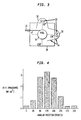
- FIG. 3 schematically illustrates apparatus for performing the on-reel cure comprising a reel 30 of partially cured fiber 31 and a pair of UV lamps 32 (each comprising a pair of bulbs 33) extending parallel to the reel axis.
- Reflectors 34 are provided for directing light from the bulbs toward the reel. Rotation of the reel about its axis provides exposure to all of the fiber.
- the second cure can be accomplished while the reel is being filled during take up or while it is being emptied during rewind, so that all layers of fiber on the reel are exposed equally to ultraviolet light.
- the ultraviolet light should be reflected to evenly illuminate the face of the reel rather than being focused to a line or point.
- the reflectors 34 extend close to the reel in order to protect workers from direct exposure to UV light, and end shields 35 are provided for the same purpose.
- FIG. 1 The method of FIG. 1 and its advantages in the fabrication of optical fiber can be better understood by consideration of the following example.
- On-reel cure experiments were carried out using UV A black light lamps illuminating a reel of fiber as it was unwound at various speeds.
- the setup was as diagrammed in FIG. 3.
- the experiments used XX-15A black lights from Spectronics Corp. These black light bulbs have a total power of 15W each, and produce approximately 1 mW/cm 2 UV A intensity at 25.4 cms (10") from the bulb.
- the bulbs are (12") 30.48 cms long, and were mounted in pairs in standard fixtures similar to fluorescent light fixtures, with integral aluminum reflectors.
- the fiber was unwound onto a takeup reel (not illuminated) and rewind was begun at the same time that the lamps were turned on. Two km of fiber were rewound in order to ensure that the unwinding reel reaches a steady cure level. Then the fiber was cut, and the fiber on the unwinding reel was examined by sampling several meter sections using infrared analysis. It was found that the increased cure due to the lamps penetrates about 750 m (of fiber) into the reel, or about 3 complete, close-packed fiber layers. (The actual amount of fiber in each layer is closer to 150 meters, because the layers are not close-packed.) The penetration depth suggests that the UV penetration is sufficient to guarantee a uniform cure on the under side vs. the top side of each fiber layer. The cure on the top layer of fiber is used as a measure of the steady state value of cure at each rewind speed.
- FIG. 5 shows the results for a fiber which has an initial primary cure level of 70%, recured with either 4 or 8 lamps.
- the boost cure with 4 lamps, representing 60W of total power, is 92% at 8 m/s rewind speed, and is better at slower speeds. With 8 lamps, the cure is essentially complete, even at 8 m/s.
- the advantages of this two-step curing process are substantial.
- the higher line speed increases throughput proportionately.
- the second cure on the reel reduces the necessary ultraviolet power by a factor of several tens to several thousand. All of the ultraviolet light can be imaged onto the face of the reel so that nearly 100% of the light is absorbed by the coating.
- the illumination can be for longer times at lower power levels which is more efficient in inducing polymerization reactions.
- a third advantage accrues because the fiber can cool from its elevated temperatures to a temperature preferably less than 50°C before the final cure. This produces an enhanced cure with enhanced pullout strength and higher in situ modulus.
Landscapes
- Life Sciences & Earth Sciences (AREA)
- Chemical & Material Sciences (AREA)
- General Life Sciences & Earth Sciences (AREA)
- Engineering & Computer Science (AREA)
- Chemical Kinetics & Catalysis (AREA)
- General Chemical & Material Sciences (AREA)
- Geochemistry & Mineralogy (AREA)
- Materials Engineering (AREA)
- Organic Chemistry (AREA)
- Surface Treatment Of Glass Fibres Or Filaments (AREA)
- Optical Fibers, Optical Fiber Cores, And Optical Fiber Bundles (AREA)
Claims (4)
- Méthode de fabrication d'une fibre optique à revêtement polymère comprenant les étapes :de tirage d'une fibre optique non revêtue (31) à partir d'une préforme (figure 1, bloc A) ;d'application en ligne sur ladite fibre tirée d'un revêtement de polymère non vulcanisé (figure 1, bloc B) ;de vulcanisation partielle dudit revêtement polymère non vulcanisé en ligne par exposition à un rayonnement ultraviolet à une vitesse dépassant 10 m/s (figure 1, bloc C) ;d'enroulement de ladite fibre sur une bobine (30) ; etde vulcanisation complète dudit revêtement polymère sur ladite bobine (figure 1, bloc D).
- Méthode selon la revendication 1, dans laquelle ledit revêtement de fibre partiellement vulcanisé est complètement vulcanisé à une température T < 50°C.
- Méthode selon la revendication 1, dans laquelle ladite étape de vulcanisation complète est effectuée par les étapes :d'enroulement de ladite fibre sur une bobine ; etd'exposition de ladite bobine à une lumière ultraviolette tandis que ladite fibre est enroulée sur ladite bobine.
- Méthode selon la revendication 1, comprenant en outre l'étape de débit de la fibre de ladite bobine dans laquelle ladite étape de vulcanisation complète est effectuée par l'étape :
d'exposition de ladite bobine à une lumière ultraviolette tandis que la fibre est débitée de ladite bobine.
Applications Claiming Priority (2)
| Application Number | Priority Date | Filing Date | Title |
|---|---|---|---|
| US42563295A | 1995-04-20 | 1995-04-20 | |
| US425632 | 1995-04-20 |
Publications (2)
| Publication Number | Publication Date |
|---|---|
| EP0738695A1 EP0738695A1 (fr) | 1996-10-23 |
| EP0738695B1 true EP0738695B1 (fr) | 2001-07-25 |
Family
ID=23687380
Family Applications (1)
| Application Number | Title | Priority Date | Filing Date |
|---|---|---|---|
| EP96302505A Expired - Lifetime EP0738695B1 (fr) | 1995-04-20 | 1996-04-10 | Méthode rapide pour l'application et le durcissement de la couche protectrice d'une fibre optique |
Country Status (3)
| Country | Link |
|---|---|
| US (1) | US5756165A (fr) |
| EP (1) | EP0738695B1 (fr) |
| DE (1) | DE69614023T2 (fr) |
Families Citing this family (21)
| Publication number | Priority date | Publication date | Assignee | Title |
|---|---|---|---|---|
| US7322122B2 (en) * | 1997-01-15 | 2008-01-29 | Draka Comteq B.V. | Method and apparatus for curing a fiber having at least two fiber coating curing stages |
| US6265018B1 (en) * | 1999-08-31 | 2001-07-24 | Lucent Technologies Inc. | Fabricating graded index plastic optical fibers |
| US6463872B1 (en) | 2000-03-31 | 2002-10-15 | Alcatel | Laser photocuring system |
| US6423417B1 (en) * | 2000-05-24 | 2002-07-23 | Reynolds Metals Company | Non-stick polymer coated aluminum foil |
| US6544658B2 (en) | 2000-05-24 | 2003-04-08 | Reynolds Metals Company | Non-stick polymer coated aluminum foil |
| US20030190130A1 (en) * | 2002-04-05 | 2003-10-09 | Paradigm Optics, Inc. | Multiple optical pathway fiber optic cable |
| ATE346316T1 (de) * | 2003-02-10 | 2006-12-15 | Nanoptics Inc | Methode und apparat zur herstellung optischer übertragungsmedien |
| US20050042387A1 (en) * | 2003-08-21 | 2005-02-24 | 3M Innovative Properties Company | Filament coating process and apparatus |
| US7708688B2 (en) * | 2004-03-15 | 2010-05-04 | Paradigm Optics, Incorporated | Polymer endoscopic shaft |
| US20070182054A1 (en) * | 2006-01-12 | 2007-08-09 | Kachmar Wayne M | Method for manufacturing product markers |
| SE535250C2 (sv) * | 2007-12-11 | 2012-06-05 | Prysmian Comm Cables And Systems Usa Llc | Metod för tillverkning av ett optiskt fiberband samt delningsbart optiskt fiberband |
| WO2010077132A1 (fr) * | 2008-12-31 | 2010-07-08 | Draka Comteq B.V. | Appareil à del uv pour le durcissement de revêtements sur des fibres de verre |
| DK2388239T3 (da) | 2010-05-20 | 2017-04-24 | Draka Comteq Bv | Hærdningsapparat, der anvender vinklede UV-LED'er |
| US8871311B2 (en) | 2010-06-03 | 2014-10-28 | Draka Comteq, B.V. | Curing method employing UV sources that emit differing ranges of UV radiation |
| JP5417531B2 (ja) * | 2010-06-11 | 2014-02-19 | 株式会社フジクラ | 光ファイバ素線の製造方法及び製造装置 |
| EP2418183B1 (fr) | 2010-08-10 | 2018-07-25 | Draka Comteq B.V. | Procédé pour le durcissement des fibres de verre revêtus avec d'intensité UVLED augmentée |
| US9283437B2 (en) | 2011-12-23 | 2016-03-15 | Nike, Inc. | Golf ball having partial cured UV coating |
| US9366536B2 (en) * | 2013-01-15 | 2016-06-14 | Honeywell International Inc. | Method and apparatus for producing fiber optic gyroscope sensing coil using B-stage adhesive coated optical fiber |
| JP2016004927A (ja) * | 2014-06-18 | 2016-01-12 | 株式会社オーク製作所 | 紫外線照射装置 |
| JP7099160B2 (ja) * | 2018-08-10 | 2022-07-12 | 住友電気工業株式会社 | 光ファイバの製造方法 |
| CN117261047A (zh) * | 2023-11-22 | 2023-12-22 | 广东美登新材料科技有限公司 | 一种高分子树脂加料监控装置 |
Family Cites Families (8)
| Publication number | Priority date | Publication date | Assignee | Title |
|---|---|---|---|---|
| JPS5917056B2 (ja) * | 1980-12-26 | 1984-04-19 | 日本電信電話株式会社 | 光伝送用ガラスファイバの製造方法 |
| JP2587679B2 (ja) * | 1988-04-28 | 1997-03-05 | 三菱電線工業株式会社 | ガラス系光ファイバの製造方法 |
| US5593736A (en) * | 1988-05-26 | 1997-01-14 | The United States Of America As Represented By The Secretary Of The Navy | Process for manufacturing a fiber reinforced optic microcable with a UV cured resin |
| US5352712A (en) * | 1989-05-11 | 1994-10-04 | Borden, Inc. | Ultraviolet radiation-curable coatings for optical fibers |
| US5219623A (en) * | 1990-03-09 | 1993-06-15 | At&T Bell Laboratories | Methods of producing an article which includes a light energy cured coating material |
| US5194112A (en) * | 1990-09-14 | 1993-03-16 | The United States Of America As Represented By The Secretary Of The Army | Method of applying a fiber optic adhesive to a fiber optic material |
| FR2691171B1 (fr) * | 1992-05-15 | 1994-12-23 | Vetrotex France Sa | Procédé de fabrication d'un fil continu par étirage mécanique et produits en résultant. |
| US5345528A (en) * | 1993-07-28 | 1994-09-06 | At&T Bell Laboratories | Method for enhancing the pullout strength of polymer-coated optical fiber |
-
1996
- 1996-04-10 EP EP96302505A patent/EP0738695B1/fr not_active Expired - Lifetime
- 1996-04-10 DE DE69614023T patent/DE69614023T2/de not_active Expired - Fee Related
- 1996-09-16 US US08/716,802 patent/US5756165A/en not_active Expired - Fee Related
Also Published As
| Publication number | Publication date |
|---|---|
| EP0738695A1 (fr) | 1996-10-23 |
| US5756165A (en) | 1998-05-26 |
| DE69614023D1 (de) | 2001-08-30 |
| DE69614023T2 (de) | 2002-03-21 |
Similar Documents
| Publication | Publication Date | Title |
|---|---|---|
| US5756165A (en) | High speed method for coating and curing optical fiber | |
| JP3952620B2 (ja) | フォトイニシエータ調整形光ファイバおよび光ファイバリボンおよびこれらの製造方法 | |
| US5440660A (en) | Fiber optic microcable produced with fiber reinforced ultraviolet light cured resin and method for manufacturing same | |
| JPS62171947A (ja) | フアイバの被覆を硬化させる方法および装置 | |
| US5636307A (en) | Fiber optic microcable produced with radiation cured composite | |
| CN1233583C (zh) | 激光光固化系统 | |
| US20020106173A1 (en) | Ultraviolet curable coatings for optical fiber for wet-on-wet application | |
| US5945173A (en) | Method of making optical fiber ribbon | |
| US5593736A (en) | Process for manufacturing a fiber reinforced optic microcable with a UV cured resin | |
| US6304705B1 (en) | Mode coupling buffered optical fiber apparatus and method for making | |
| CA2177215C (fr) | Methode pour l'obtention de faisceaux de fibres optiques grace a un adhesif sechant aux rayons ultraviolets | |
| US4774104A (en) | Irradiation device, arrangement for and method of cladding a filamentary body | |
| AU681207B2 (en) | Process for manufacturing optical fiber ribbons | |
| JPH09278495A (ja) | 光ファイバの被膜形成と硬化を高速で行う方法 | |
| CN1033983A (zh) | 对光导纤维涂层进行强化处理的方法和设备 | |
| GB2166975A (en) | Optical fibres | |
| US5688553A (en) | Polyimide coated heavy metal fluoride glass fiber and method of manufacture | |
| US5345528A (en) | Method for enhancing the pullout strength of polymer-coated optical fiber | |
| JP2004521382A (ja) | 温度範囲を調整された被覆光ファイバーの製造方法 | |
| US12140813B2 (en) | Low-attenuation rollable optical fiber ribbon | |
| EP0873977B1 (fr) | Procédé de revêtement d'une fibre optique | |
| JPS6057811A (ja) | プラステイツク光フアイバコ−ドの製造方法 | |
| JPH0251856B2 (fr) | ||
| JPH02186310A (ja) | 光ファイバ心線 | |
| JPS63156042A (ja) | 光フアイバ用紫外線照射装置 |
Legal Events
| Date | Code | Title | Description |
|---|---|---|---|
| PUAI | Public reference made under article 153(3) epc to a published international application that has entered the european phase |
Free format text: ORIGINAL CODE: 0009012 |
|
| AK | Designated contracting states |
Kind code of ref document: A1 Designated state(s): DE FR GB |
|
| 17P | Request for examination filed |
Effective date: 19970410 |
|
| 17Q | First examination report despatched |
Effective date: 19981026 |
|
| GRAG | Despatch of communication of intention to grant |
Free format text: ORIGINAL CODE: EPIDOS AGRA |
|
| GRAG | Despatch of communication of intention to grant |
Free format text: ORIGINAL CODE: EPIDOS AGRA |
|
| GRAH | Despatch of communication of intention to grant a patent |
Free format text: ORIGINAL CODE: EPIDOS IGRA |
|
| GRAH | Despatch of communication of intention to grant a patent |
Free format text: ORIGINAL CODE: EPIDOS IGRA |
|
| GRAA | (expected) grant |
Free format text: ORIGINAL CODE: 0009210 |
|
| AK | Designated contracting states |
Kind code of ref document: B1 Designated state(s): DE FR GB |
|
| RIC1 | Information provided on ipc code assigned before grant |
Free format text: 7C 03C 25/10 A, 7G 02B 6/44 B |
|
| REF | Corresponds to: |
Ref document number: 69614023 Country of ref document: DE Date of ref document: 20010830 |
|
| ET | Fr: translation filed | ||
| REG | Reference to a national code |
Ref country code: GB Ref legal event code: IF02 |
|
| PLBE | No opposition filed within time limit |
Free format text: ORIGINAL CODE: 0009261 |
|
| STAA | Information on the status of an ep patent application or granted ep patent |
Free format text: STATUS: NO OPPOSITION FILED WITHIN TIME LIMIT |
|
| 26N | No opposition filed | ||
| PG25 | Lapsed in a contracting state [announced via postgrant information from national office to epo] |
Ref country code: DE Free format text: LAPSE BECAUSE OF NON-PAYMENT OF DUE FEES Effective date: 20021101 |
|
| PGFP | Annual fee paid to national office [announced via postgrant information from national office to epo] |
Ref country code: FR Payment date: 20030418 Year of fee payment: 8 |
|
| REG | Reference to a national code |
Ref country code: FR Ref legal event code: ST |
|
| PG25 | Lapsed in a contracting state [announced via postgrant information from national office to epo] |
Ref country code: FR Free format text: LAPSE BECAUSE OF NON-PAYMENT OF DUE FEES Effective date: 20041231 |
|
| REG | Reference to a national code |
Ref country code: FR Ref legal event code: ST |
|
| PGFP | Annual fee paid to national office [announced via postgrant information from national office to epo] |
Ref country code: GB Payment date: 20070628 Year of fee payment: 12 |
|
| GBPC | Gb: european patent ceased through non-payment of renewal fee |
Effective date: 20080410 |
|
| PG25 | Lapsed in a contracting state [announced via postgrant information from national office to epo] |
Ref country code: GB Free format text: LAPSE BECAUSE OF NON-PAYMENT OF DUE FEES Effective date: 20080410 |