EP0739010A2 - Circuit pour détecter la location de défaut de signal - Google Patents
Circuit pour détecter la location de défaut de signal Download PDFInfo
- Publication number
- EP0739010A2 EP0739010A2 EP96420107A EP96420107A EP0739010A2 EP 0739010 A2 EP0739010 A2 EP 0739010A2 EP 96420107 A EP96420107 A EP 96420107A EP 96420107 A EP96420107 A EP 96420107A EP 0739010 A2 EP0739010 A2 EP 0739010A2
- Authority
- EP
- European Patent Office
- Prior art keywords
- positive
- drop
- negative
- peak
- pulse
- Prior art date
- Legal status (The legal status is an assumption and is not a legal conclusion. Google has not performed a legal analysis and makes no representation as to the accuracy of the status listed.)
- Withdrawn
Links
- 238000001514 detection method Methods 0.000 title description 3
- 230000002401 inhibitory effect Effects 0.000 claims description 6
- 230000004044 response Effects 0.000 claims description 6
- 230000003287 optical effect Effects 0.000 abstract description 2
- 238000013500 data storage Methods 0.000 abstract 1
- 230000007704 transition Effects 0.000 description 16
- 238000000034 method Methods 0.000 description 9
- 230000008859 change Effects 0.000 description 4
- 230000003111 delayed effect Effects 0.000 description 4
- 238000012986 modification Methods 0.000 description 3
- 230000004048 modification Effects 0.000 description 3
- 238000011084 recovery Methods 0.000 description 3
- 230000003190 augmentative effect Effects 0.000 description 2
- 238000012937 correction Methods 0.000 description 2
- 238000010586 diagram Methods 0.000 description 2
- 230000000694 effects Effects 0.000 description 2
- 230000005415 magnetization Effects 0.000 description 2
- 238000012545 processing Methods 0.000 description 2
- 102100028626 4-hydroxyphenylpyruvate dioxygenase Human genes 0.000 description 1
- 101100117236 Drosophila melanogaster speck gene Proteins 0.000 description 1
- 230000007547 defect Effects 0.000 description 1
- 230000004069 differentiation Effects 0.000 description 1
- 239000000839 emulsion Substances 0.000 description 1
- 230000004907 flux Effects 0.000 description 1
- 230000006870 function Effects 0.000 description 1
- 238000010348 incorporation Methods 0.000 description 1
- 239000006247 magnetic powder Substances 0.000 description 1
- 238000004519 manufacturing process Methods 0.000 description 1
- 238000002250 neutron powder diffraction Methods 0.000 description 1
- 229920002469 poly(p-dioxane) polymer Polymers 0.000 description 1
- 239000000725 suspension Substances 0.000 description 1
- 238000004804 winding Methods 0.000 description 1
Images


Classifications
-
- H—ELECTRICITY
- H03—ELECTRONIC CIRCUITRY
- H03K—PULSE TECHNIQUE
- H03K5/00—Manipulating of pulses not covered by one of the other main groups of this subclass
- H03K5/19—Monitoring patterns of pulse trains
-
- G—PHYSICS
- G11—INFORMATION STORAGE
- G11B—INFORMATION STORAGE BASED ON RELATIVE MOVEMENT BETWEEN RECORD CARRIER AND TRANSDUCER
- G11B20/00—Signal processing not specific to the method of recording or reproducing; Circuits therefor
- G11B20/10—Digital recording or reproducing
- G11B20/18—Error detection or correction; Testing, e.g. of drop-outs
- G11B20/1833—Error detection or correction; Testing, e.g. of drop-outs by adding special lists or symbols to the coded information
Definitions
- This invention relates to electrical circuits suitable for decoding binary information from analog signal and clock patterns read out of a storage media, and particularly to such circuits for locating drop-outs in the recorded analog signal patterns.
- Magnetic recording stores information in a hard magnetic layer of a magnetic medium by setting the direction of magnetization of regions of the layer.
- a recording apparatus of the type using a magnetic disk, magnetic tape or similar magnetic recording medium reproduces stored digital data in the form of an analog waveform representative of transitions of magnetic polarity on the recording medium.
- data recorded in an NRZ (non-return to zero) or NRZI (non-return to zero inverted) recording pattern for example, positive and negative peaks follow one another in succession with transitions between the peaks passing through the signal baseline.
- the positive and negative peaks may represent explicit data bit values, in self-clocking codes, or may represent explicit clock bits and encoded data bits in pulse position or interval modulation codes.
- One form of a digital data reproducing circuit for reading any such recorded code differentiates the reproduced waveform and determines the points where the differentiated waveform crosses a zero level representative of zero AC volts, to detect the peaks.
- a photographic filmstrip having a virtually transparent, magnetic film layer covering the non-emulsion side of the filmstrip (referred to as an MOF layer) is disclosed in conjunction with various camera systems.
- Potential longitudinal recording tracks are illustrated in the MOF layer in both the image frame area and on either side of the image frame area for recording information such as film type, film speed, film exposure information and information relevant to the processing and subsequent use (e.g., printing) of the exposed image frames.
- the systems disclosed therein provide for recording of information during film manufacture, reading and/or recording of information on certain tracks during camera use, and reading and/or recording of printer related information during photofinishing.
- Novel methods for modulating the binary data or information into a format suitable for recording and reproducing in such tracks in the camera shown in the '419 patent are disclosed in commonly assigned U.S. Patent No. 4,964,139, also to Wash et al.
- Two self synchronizing PPM coding methods are disclosed in the ⁇ 139 patent, as the "Wash encoded signal” and the “Chi encoded signal” methods. Both PPM encoding methods have similarities as pointed out in the ⁇ 139 patent, and the Wash encoded signal method is further referred to herein for purposes of explaining how the present invention may be practiced in at least one of its preferred embodiments in locating drop-outs in magnetically recorded data encoded in such a manner.
- FIG. 1 An example of the Wash encoding method, as used to record data in bit streams in the MOF layer tracks described in the ⁇ 419 patent, is shown in FIG. 1 which essentially reproduces Figure 3 of the ⁇ 139 patent.
- two successive bits 0 and 1 are position encoded in the two corresponding "interval or information-cells" as positive going data signal level transitions bounded by negative going clock signal transitions between the directions of magnetization.
- the Wash self-clocking bit code is effected by the position of the positive going data signal level transition in the information-cell. If it is positioned within the first half of the duration of the information-cell, then a data bit 0 is recorded. Similarly, a data bit 1 is recorded by positioning the data transition in the second half of the information-cell.
- the data bit may in fact be a parity bit, as the two terms are used below.
- the encoding of the information or data transitions for both the first and second information-cells leaves invariant the clock transitions.
- film transport velocity can vary during recording and playback without affecting the ability to synchronize and read the recorded data.
- the information-cells may lengthen or shorten depending on the filmstrip velocity, but the relative position of the data transitions can still be decoded.
- the camera disclosed in the ⁇ 419 patent may record data in the MOF layer tracks while winding the filmstrip between exposures without imposing any velocity controls or recording an independent clock track.
- large amounts of jitter in the camera transport at frequencies at or near the data frequencies precludes the use of a phase-locked loop in generating a clock during magnetic signal read out.
- the PPM information-cells are decoded by means of a head sensitive to the field or rate of change of the flux emanating from the polarized regions at the transition zones.
- the signal produced by most magnetic reproduce heads is a voltage pulse corresponding to the location of a transition zone from one magnetically set region to another.
- the detection circuitry to which the head is attached must determine the location of one peak relative to another. This is most often done by differentiating the pulse and comparing the voltage to zero.
- the differentiated waveform will cross zero at a time corresponding to the peak in the original waveform, at which point the comparator will change state. This works well in the region where the pulse has energy. However, outside this region, the input to the comparator hovers around zero, crossing zero as a result of noise, producing transitions at the output.
- the output of the comparator is gated by a circuit which only allows the comparator state to change when the input waveform exceeds a threshold, usually 30% - 45% of the peak amplitude.
- a threshold usually 30% - 45% of the peak amplitude.
- This scheme works well in eliminating the unwanted transitions.
- a side effect is that, if the peak amplitude of the input signal fails to reach the threshold, no transition will occur and the data will be missed.
- Hard disk drives deal with this problem by marking locations on the disk where this occurs and not using the areas.
- Tape drives use frequent re-synching, read-while-write, rereading, and powerful error correction code (ECC) to deal with the problem. Simple, inexpensive systems for use in cameras cannot use such complex and expensive solutions, and resort is therefor made to the self clocking PPM coding of Wash or Chi.
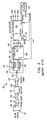
- a read/write magnetic head 12 provides the read signals of Figure 1B on lines 14.
- a pre-amplifier 16 amplifies the output signal from the magnetic head 12 and applies the amplified signal on lines 26 to a filter 18 for removing an unnecessary component from the amplified read signals.
- a post-amplifier 20 amplifies the filtered read signals and applies the filtered and amplified, positive and negative, signals to a detector 24 via line 22.
- the signals are applied to a positive peak detector (PPD) 30 and a negative peak detector (NPD) 32 for detecting the negative and positive pulses having amplitudes exceeding respective threshold levels to ensure that noise signals are not decoded as data or clock signals.
- PPD positive peak detector
- NPD negative peak detector
- Uniform amplitude, polarity, and pulse width, clock and data, signal pulse trains are thereby generated on lines 38 and 34 as depicted in Figure 1C.
- a delay circuit 40 is connected to the NPD 32 via line 38, resulting in a delayed clock pulse train on lines 46 and 48 and also appearing in Figure 1C.
- the delayed clock signal is applied to the set terminal of the flip-flop 36 and is also applied to clear the up/down counter 50.
- the data signal is applied to the clear terminal of the flip-flop 36, so that the flip-flop 36 is set by delayed clock signals and cleared by data signals to provide the square wave signal shown in Figure 1D at the Q output.
- the Q output is set high by a delayed clock signal and low by the succeeding data signal.
- the up/down counter 50 counts system clock 56 pulses applied to its CLK input, incrementing the count when the Q output is high and decrementing the count when the Q output is low.
- the most significant bit (MSB) of the output count of the up/down counter 50 and the CLOCK output from the NPD 32 are supplied to a computer 42.
- MSB most significant bit
- the conventional data read out circuit compares the absolute positive and negative amplitudes of the reproduced analog waveforms to threshold levels in the PPD and NPD circuits to convert, among the above-mentioned peaks, only the peaks having amplitudes higher than a predetermined threshold level into digital signals, determining that they are data bits 1 or 0 depending on their position in the case of the PPM encoded signals.
- the amplitudes of the pulse signals fade below the thresholds, both the clock pulses separating successive information-cells and the data pulses signifying the binary data content can be lost.
- a block of three data bytes of eight information-cells is shown.
- the first bit of each byte is a parity bit (P i ), and the remaining seven bits are data bits (d i1 - d i7 ).
- Each block of bytes recorded serially in a single track in the MOF layer is separated by a parity byte, called a Longitudinal Redundancy Check (LRC).
- LRC Longitudinal Redundancy Check
- Each vertical column bit value of the LRC is calculated from the values of the data bits in its respective column.
- the data bits of successive information-cells in each block are thereby protected with a 2-dimensional, horizontal and vertical, parity check in the data blocks. This scheme is able to correct an odd number of bits in error in any one byte, provided a bit is present at every position and the LRC is present in its proper position with the longitudinal parity bits lined up with their respective columns.
- the PPM encoding method described above incorporates the clock information in with the data so that a drop-out typically results in both loss of data content and loss of the clock signal.
- a drop-out occurs, no clock is available to transmit data from the decoder to the memory, so that bits are completely missing in the recovered data block. This results in loss of byte synchronization and renders the parity checks useless in recovering the uncorrupted data.
- a method of and apparatus for locating drop-outs in the read out peak signal patterns of encoded data comprising the steps of and means for: providing a first threshold for decoding a peak of the read out signal pattern as a valid peak; providing a second threshold lower in absolute magnitude than the first threshold indicative of a drop-out in the recorded signal pattern magnitude; comparing the read out signal pattern to the first and second thresholds; decoding a valid peak detect pulse when a predetermined relationship between the magnitude of the read out signal pattern and the first threshold exists; and decoding a drop-out pulse when a predetermined relationship between the magnitude of the read out signal pattern and the second threshold exists.
- the method and apparatus preferably further comprises the step of and means for inhibiting the decoding of the drop-out pulse when the predetermined relationship between the magnitude of the read out signal pattern and the first threshold exists.
- the peaks of the read out signal pattern are detected to provide a timing pulse in response thereto, and the inhibiting step or means operates to negate the decoding of the drop-out pulse in response to the timing pulse and the decoding of the valid peak detect pulse.
- the invention is preferably practiced with a NRZ or NRZI Wash et al. code as described above or other codes wherein the encoded data comprises magnetically recorded signal patterns having successive positive and negative peaks signifying information content by relative position of the peaks.
- positive and negative peak detect and drop-out thresholds are provided or employed for deriving both the positive and negative peak detect pulses and drop-out pulses.
- the present invention describes a peak detector circuit which may provide an indication as to when a drop-out begins and ends.
- this information allows systems to recover lost information with simple ECC codes or redundant recording of the data.
- the identification of the beginning and/or end of a drop-out ensures that the data is not misinterpreted and employed incorrectly, e.g. in processing a filmstrip having such encoded data recorded in the MOF layer tracks, for example.
- the number of missing bits can be determined. Once the number of bits are determined, the location in the stream of bytes can be determined.
- the present invention may be implemented into a system for decoding the Wash self clocking PPM signal levels in a read out circuit similar to that of Figure 2 with modifications made to the peak detector 24 and incorporation of the operations of flip-flop 36, delay 40 and counter 50 into a microprocessor-based microcomputer.
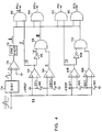
- the modified peak detector 64 includes a first PPD and NPD which detect peak signal levels that exceed (in absolute terms) the data and clock thresholds for decoding data and clock pulses and a second PPD and NPD which detect peak signal levels that exceed (in absolute terms) a lower threshold pair for detecting sub-threshold data and clock pulses occurring as the signal level drops out.
- the pulse signal waveform is inverted from those shown in Figure 1B, but may be assumed to be equivalent thereto in function and with reversal of designations of the output signals of the PPDs and NPDs.
- the PPM encoded data bit pattern is identified in Figure 3B. A drop-out region is evidenced by the loss of amplitude of the pulse peaks.
- the positive clock pulse threshold CT+ is augmented by a lower amplitude, positive clock drop-out pulse threshold CDT+.
- the negative data pulse threshold DT- is augmented by a higher amplitude, negative data drop-out pulse threshold DDT-. Any pulse peaks of the PPM signal falling in the positive or negative threshold ranges between the two thresholds CT+ and CDT+ or DDT- and DT- provides drop-out pulses DO+ or DO-, respectively, marking those peaks as bounding a drop-out region (as shown in Figure 3D for DO+). Positive (clock) and negative (data) pulse peaks exceeding both thresholds are indicated by trains of peak pulses PD+ and PD- appearing in Figures 3C and 3E. In this example, the negative data pulse peaks in the drop-out zone all fall below (in absolute terms) the data drop-out pulse threshold DDT-, and so none appear in Figure 3F.
- the four thresholds are set in the modified peak detector 64 of Figure 4 by the reference voltages applied to input terminals of the modified PPD 70 and the modified NPD 72 which both receive the signal of Figure 3A.
- Differentiator 74, comparator 76, and bi-directional one-shot 78 form a modified peak detector 64 that outputs a timing pulse for each peak in the incoming signal waveform, regardless of polarity and amplitude. It will be understood that differentiator 74 may be replaced by an integrator or a non-linear peak detector of types known in the art having good signal-to-noise discrimination.
- the incoming signal waveform is applied to positive input terminals of comparators 92 and 94 of the modified PPD 70 and to the negative input terminals of comparators 104 and 106 of the modified NPD 72.
- the modified PPD 70 and NPD 72 develop the pulse trains PD+ and PD- appearing in Figures 3C and 3E at the outputs of AND gates 80 and 82 or the pulse trains DO- and DO+ at the outputs of AND gates 84 and 86, except when the positive and negative signal peaks fall below both thresholds.
- the differentiator 74, comparator 76 and one shot 78 are set to output the timing pulse near the positive or negative pulse signal peak such that the timing pulse duration falls within the duration of the output signals from comparators 92 and 104.
- First and second positive thresholds are set by the resistor pair 88 and 90 between +Vref and system ground.
- the positive pulse threshold voltages CT+ and CDT+ developed thereby are applied to the negative input terminals of comparators 92 and 94, respectively.
- the output signal of comparator 92 is applied to one input of AND gate 80 and to inverter 96, where it is inverted and applied to one input of AND gate 98.
- the output signal of comparator 94 is applied to the other input of AND gate 98, and the output of AND gate 98 is applied to an input of AND gate 84.
- the other terminals of AND gates 80 and 84 receive the timing pulse from one-shot 78.
- the negative threshold range is provided by the resistor pair 100 and 102 between -Vref and system ground.
- the negative threshold voltages DT- and DDT-developed thereby are applied to the positive input terminals of comparators 104 and 106, respectively.
- the output signal of comparator 104 is applied to one input of AND gate 82 and to inverter 108, where it is inverted and applied to one input of AND gate 110.
- the output signal of comparator 102 is applied to the other input of AND gate 110, and the output of AND gate 110 is applied to an input of AND gate 86.
- the other terminals of AND gates 82 and 86 receive the timing pulse from one shot 78.
- comparators 92 and 104 compare the first, upper (absolute value) threshold levels CT+ and DT- for a valid clock or data peak to the incoming read out signal pattern.
- Comparators 94 and 106 compare the second, lower (absolute value) threshold levels CDT+ and DDT- to the incoming read out signal pattern shown in Figure 3A.
- the timing pulse is developed from the differentiation and zero crossing detection of the peak magnitude of the read out signal pattern.
- comparators 92 and 94 both go high at the point where their respective thresholds are exceeded.
- the positive pulse output of comparator 92 and the timing pulse are simultaneously applied to AND gate 80, allowing the peak detect pulse PD+ to be transmitted to the decoder.
- the inverted pulse from inverter 96 disables AND gate 98 for the duration of the positive pulse output. Consequently, a pair of pulses may be passed by the AND gate 98 and applied to one input of AND gate 84 bracketing the timing pulse. Since the pulses do not overlap, the output of AND gate 84 does not go high and does not provide the drop-out pulse DO+. In this fashion, the decoding of the drop-out pulse DO+ is inhibited or negated when the peak magnitude of the read out signal pattern exceeds the first and second thresholds CT+ and CDT+ and the decoding of the valid peak detect pulse PD+ is allowed.
- comparator 94 applies its somewhat narrower high pulse output to AND gate 98 while the other input state is high, resulting in a high output applied to one input of AND gate 84 at the same time that the timing pulse is present at the other input. Therefore, the output of AND gate 84 goes high for the overlapping duration of the two pulses, resulting in the generation of the drop-out signal DO+ applied to the decoder.
- the NPD 72 operates in a similar fashion to compare negative going data pulse signals to the third and fourth thresholds DT- and DDT- to develop either the PD- or DO-pulse signals of Figures 3E or 3F.
- the timing pulse generated by one-shot 78 inhibits and negates the passage of drop-out pulse DO- through AND gate 86 when the magnitude of the negative, data peak exceeds the third threshold DT- and the peak detect pulse PD- is passed through gate 82.
- the second and fourth thresholds CDT+ and DDT- are set such that at least one positive or negative peak will fall in the positive or negative threshold range during either the onset or the end of a drop-out. This range will vary depending on the type of media and head used in the system.
- the invention as described above is usable in any form of magnetic or optical recording or the like on any medium. Moreover, it may be used in any type of peak recording data coding other than the above described, NRZ or NRZI PPM code.
- a number of advantages flow as a result of being able to detect the onset of a drop-out and the recovery or drop-in peak. Frequently, drop-outs of just a few bits occur, typically because of a momentary loss of contact of the head with the magnetic media as described above. In a typical clocked code, the number of missing bits can be determined. Once the number of bits are determined, the location in the stream of bytes can be determined.
- the bytes of a data block are redundantly recorded, and the bytes located thereby having the drop-out bits can be ignored in favor of the back-up bytes.
- the corrupted data byte may be reconstituted from the LRC and the byte parity bits P 1 ... P n .
- the DO+ or DO- code is maintained in a parallel register corresponding to the bit location d 24 and/or d 25 .
- the Table II data stream may be shifted as shown in Table III until the column parity bits for the parity column and the data columns 1-4 are correct: Shifted Data P 1 d 11 d 12 d 13 d 14 d 15 d 16 d 17 P 2 d 21 d 22 d 23 d 24 X X X P 3 d 31 d 32 d 33 d 34 d 35 d 36 d 37 P P P P P P P P P P P P P P P P P P P P P P P P P P P P P P P P P P P P P P P P P P P P P P P P P P P P P P P P
Landscapes
- Physics & Mathematics (AREA)
- Nonlinear Science (AREA)
- Engineering & Computer Science (AREA)
- Signal Processing (AREA)
- Signal Processing For Digital Recording And Reproducing (AREA)
- Error Detection And Correction (AREA)
- Dc Digital Transmission (AREA)
Applications Claiming Priority (2)
| Application Number | Priority Date | Filing Date | Title |
|---|---|---|---|
| US08/424,916 US5627846A (en) | 1995-04-19 | 1995-04-19 | Drop-out location detection circuit |
| US424916 | 1995-04-19 |
Publications (2)
| Publication Number | Publication Date |
|---|---|
| EP0739010A2 true EP0739010A2 (fr) | 1996-10-23 |
| EP0739010A3 EP0739010A3 (fr) | 1998-01-07 |
Family
ID=23684420
Family Applications (1)
| Application Number | Title | Priority Date | Filing Date |
|---|---|---|---|
| EP96420107A Withdrawn EP0739010A3 (fr) | 1995-04-19 | 1996-04-03 | Circuit pour détecter la location de défaut de signal |
Country Status (3)
| Country | Link |
|---|---|
| US (1) | US5627846A (fr) |
| EP (1) | EP0739010A3 (fr) |
| JP (1) | JPH08293169A (fr) |
Cited By (1)
| Publication number | Priority date | Publication date | Assignee | Title |
|---|---|---|---|---|
| GB2377316A (en) * | 2001-07-07 | 2003-01-08 | Hewlett Packard Co | Drop-out management in a data read channel |
Families Citing this family (3)
| Publication number | Priority date | Publication date | Assignee | Title |
|---|---|---|---|---|
| US6640328B1 (en) * | 1998-09-22 | 2003-10-28 | Conexant Systems, Inc. | Method for detecting dropouts in data delivered over a bandwidth-limited bus |
| US6993705B1 (en) * | 2000-12-21 | 2006-01-31 | Emc Corporation | Cyclic redundancy check (CRC) parity check system and method |
| US6501607B2 (en) * | 2001-01-10 | 2002-12-31 | Texas Instruments Incorporated | Channel quality monitor (CQM) for digital peak detection (DPD) |
Family Cites Families (24)
| Publication number | Priority date | Publication date | Assignee | Title |
|---|---|---|---|---|
| US3629823A (en) * | 1969-11-14 | 1971-12-21 | Gen Dynamics Corp | Information-handling system having error correction capabilities |
| US3715738A (en) * | 1970-10-19 | 1973-02-06 | Peripheral Business Equipment | Data detection system |
| JPS5143367B2 (fr) * | 1972-07-07 | 1976-11-20 | ||
| US4025917A (en) * | 1975-11-06 | 1977-05-24 | The United States Of America As Represented By The Secretary Of The Navy | Simplified time code reader with digital PDM decoder |
| NL8003477A (nl) * | 1980-06-16 | 1982-01-18 | Philips Nv | Inrichting voor het verwerken van serieele informatie welke is voorzien van synchronisatiewoorden. |
| US4449222A (en) * | 1981-11-23 | 1984-05-15 | Rockwell International Corporation | Digital modulation quality monitor |
| CA1212729A (fr) * | 1981-12-08 | 1986-10-14 | Hiroshi Ogawa | Circuit de detection et de correction de signaux numeriques avec generateur de signaux de portillonnage reglables |
| DE3238077A1 (de) * | 1982-10-14 | 1984-04-19 | Basf Ag, 6700 Ludwigshafen | Verfahren und schaltungsanordnungen zum auffinden und auswerten von fehlstellen auf aufzeichnungstraegern mit in wenigstens einer spur aufgezeichneten digitalsignalen |
| EP0110105B1 (fr) * | 1982-12-01 | 1987-03-18 | International Business Machines Corporation | Systèmes pour la lecture d'enregistrements magnétiques |
| US4613769A (en) * | 1984-08-13 | 1986-09-23 | National Semiconductor Corporation | Direct current coupled peak to peak detector circuit |
| US5148291A (en) * | 1986-05-21 | 1992-09-15 | Canon Kabushiki Kaisha | Apparatus for displaying image signal drop-out |
| DE3733278A1 (de) * | 1987-09-29 | 1989-04-13 | Siemens Ag | Messverfahren zur stoerungsanalyse digitaler uebertragungswege und messeinrichtung zur durchfuehrung des messverfahrens |
| EP0344669B1 (fr) * | 1988-05-28 | 1994-08-17 | Nec Corporation | Circuit de reproduction de données numériques pour un appareil d'enregistrement magnétique |
| US4977419A (en) * | 1988-10-07 | 1990-12-11 | Eastman Kodak Company | Self-clocking encoding/decoding film information exchange system using dedicated magnetic tracks on film |
| JPH0712166B2 (ja) * | 1988-12-05 | 1995-02-08 | 富士通株式会社 | 同期多重伝送装置 |
| US4964139A (en) * | 1989-04-27 | 1990-10-16 | Eastman Kodak Company | Multi-purpose circuit for decoding binary information |
| US5105316A (en) * | 1989-11-20 | 1992-04-14 | Seagate Technology, Inc. | Qualification for pulse detecting in a magnetic media data storage system |
| JPH03232024A (ja) * | 1990-02-08 | 1991-10-16 | Zexel Corp | ウオッチドッグタイマ回路 |
| US5111485A (en) * | 1990-05-18 | 1992-05-05 | Northern Telecom Limited | Method of and circuit for synchronizing data |
| EP0556445A1 (fr) * | 1991-10-01 | 1993-08-25 | Fujitsu Limited | Détecteur de crêtes pour le suivi de piste dans un dispositif de disques magnétiques |
| US5313236A (en) * | 1991-11-28 | 1994-05-17 | Canon Kabushiki Kaisha | Demodulation processing circuit with time interval counting feature |
| US5301207A (en) * | 1992-04-03 | 1994-04-05 | Integrated Network Corporation | Test apparatus and process for digital data service system |
| US5293369A (en) * | 1992-10-28 | 1994-03-08 | International Business Machines Corporation | Asynchronous sampling digital detector system for magnetic and optical recording channels |
| US5345216A (en) * | 1993-02-26 | 1994-09-06 | Storage Technology Corporation | Method and apparatus for qualifying data peaks |
-
1995
- 1995-04-19 US US08/424,916 patent/US5627846A/en not_active Expired - Lifetime
-
1996
- 1996-04-03 EP EP96420107A patent/EP0739010A3/fr not_active Withdrawn
- 1996-04-05 JP JP8083538A patent/JPH08293169A/ja active Pending
Cited By (4)
| Publication number | Priority date | Publication date | Assignee | Title |
|---|---|---|---|---|
| GB2377316A (en) * | 2001-07-07 | 2003-01-08 | Hewlett Packard Co | Drop-out management in a data read channel |
| GB2378568A (en) * | 2001-07-07 | 2003-02-12 | Hewlett Packard Co | Drop-out management in a data read channel |
| GB2378568B (en) * | 2001-07-07 | 2004-08-25 | Hewlett Packard Co | Drop-out management system and method |
| US7039835B2 (en) | 2001-07-07 | 2006-05-02 | Hewlett-Packard Development Company, L.P. | Drop-out management system and method |
Also Published As
| Publication number | Publication date |
|---|---|
| EP0739010A3 (fr) | 1998-01-07 |
| US5627846A (en) | 1997-05-06 |
| JPH08293169A (ja) | 1996-11-05 |
Similar Documents
| Publication | Publication Date | Title |
|---|---|---|
| US5615223A (en) | PPM decoder utilizing drop-out location information | |
| JPH09326169A (ja) | 磁気テープにおいてデジタル・データをフォーマット及び記録/再生するための装置と方法 | |
| JP3428039B2 (ja) | 同期信号検出器、同期信号検出方法及び復号化装置 | |
| US4183066A (en) | Technique for recording data on magnetic disks at plural densities | |
| US5627846A (en) | Drop-out location detection circuit | |
| US20020023248A1 (en) | Medium defect detection method and data storage apparatus | |
| US5175655A (en) | Method and apparatus for verifying a signal recorded in an encoded form on a medium | |
| JP2722647B2 (ja) | 磁気テープ制御装置 | |
| KR0147081B1 (ko) | 기록매체의 디코딩장치 및 재생장치 | |
| CA1156360A (fr) | Dispositif pour enlever les corps etrangers de la pointe de lecture d'un lecteur de disques video durant la lecture | |
| EP0482621B1 (fr) | Appareil d'enregistrement/reproduction pour enregistrer et reproduire des données digitales | |
| EP0242093A1 (fr) | Resynchronisation de blocs de données en série | |
| US5264970A (en) | Digital signal reproducing apparatus | |
| JP3208808B2 (ja) | 磁気ディスク装置 | |
| Baugh et al. | Extremely low error rate digital recording with a helical scan recorder | |
| JPH0127490B2 (fr) | ||
| US3706084A (en) | Mass memory system | |
| JP3489538B2 (ja) | 情報記録方法及び情報記録装置 | |
| JP2560047Y2 (ja) | 磁気テープ記録再生装置の異常ブロック弁別機構 | |
| KR100250577B1 (ko) | 비디오 씨디의 동기 검출장치 | |
| JPH03116588A (ja) | 光ディスク装置 | |
| JPH0346167A (ja) | 復調回路 | |
| Roth | Improving Mass Storage Data Integrity | |
| JPS61126669A (ja) | エラ−修正方式 | |
| JPH06139727A (ja) | 磁気ディスクおよび磁気ディスク装置 |
Legal Events
| Date | Code | Title | Description |
|---|---|---|---|
| PUAI | Public reference made under article 153(3) epc to a published international application that has entered the european phase |
Free format text: ORIGINAL CODE: 0009012 |
|
| AK | Designated contracting states |
Kind code of ref document: A2 Designated state(s): DE FR GB |
|
| PUAL | Search report despatched |
Free format text: ORIGINAL CODE: 0009013 |
|
| AK | Designated contracting states |
Kind code of ref document: A3 Designated state(s): DE FR GB |
|
| 17P | Request for examination filed |
Effective date: 19980622 |
|
| 17Q | First examination report despatched |
Effective date: 19980810 |
|
| STAA | Information on the status of an ep patent application or granted ep patent |
Free format text: STATUS: THE APPLICATION IS DEEMED TO BE WITHDRAWN |
|
| 18D | Application deemed to be withdrawn |
Effective date: 19981222 |