EP0739057B1 - Einrichtung zum Anschliessen eines Kabelschirms - Google Patents
Einrichtung zum Anschliessen eines Kabelschirms Download PDFInfo
- Publication number
- EP0739057B1 EP0739057B1 EP96400805A EP96400805A EP0739057B1 EP 0739057 B1 EP0739057 B1 EP 0739057B1 EP 96400805 A EP96400805 A EP 96400805A EP 96400805 A EP96400805 A EP 96400805A EP 0739057 B1 EP0739057 B1 EP 0739057B1
- Authority
- EP
- European Patent Office
- Prior art keywords
- chamber
- shaft
- chimney
- shoulder
- diameter
- Prior art date
- Legal status (The legal status is an assumption and is not a legal conclusion. Google has not performed a legal analysis and makes no representation as to the accuracy of the status listed.)
- Expired - Lifetime
Links
- 238000011084 recovery Methods 0.000 description 10
- 238000002788 crimping Methods 0.000 description 4
- 238000007789 sealing Methods 0.000 description 4
- 238000005192 partition Methods 0.000 description 3
- 238000012423 maintenance Methods 0.000 description 2
- 238000004519 manufacturing process Methods 0.000 description 2
- 239000002184 metal Substances 0.000 description 2
- 230000004224 protection Effects 0.000 description 2
- 230000001681 protective effect Effects 0.000 description 2
- UQMRAFJOBWOFNS-UHFFFAOYSA-N butyl 2-(2,4-dichlorophenoxy)acetate Chemical compound CCCCOC(=O)COC1=CC=C(Cl)C=C1Cl UQMRAFJOBWOFNS-UHFFFAOYSA-N 0.000 description 1
- 239000004020 conductor Substances 0.000 description 1
- 230000003247 decreasing effect Effects 0.000 description 1
- 238000009434 installation Methods 0.000 description 1
- 239000000463 material Substances 0.000 description 1
- 238000000034 method Methods 0.000 description 1
- 238000012544 monitoring process Methods 0.000 description 1
Images


Classifications
-
- H—ELECTRICITY
- H01—ELECTRIC ELEMENTS
- H01R—ELECTRICALLY-CONDUCTIVE CONNECTIONS; STRUCTURAL ASSOCIATIONS OF A PLURALITY OF MUTUALLY-INSULATED ELECTRICAL CONNECTING ELEMENTS; COUPLING DEVICES; CURRENT COLLECTORS
- H01R13/00—Details of coupling devices of the kinds covered by groups H01R12/70 or H01R24/00 - H01R33/00
- H01R13/62—Means for facilitating engagement or disengagement of coupling parts or for holding them in engagement
- H01R13/622—Screw-ring or screw-casing
-
- H—ELECTRICITY
- H01—ELECTRIC ELEMENTS
- H01R—ELECTRICALLY-CONDUCTIVE CONNECTIONS; STRUCTURAL ASSOCIATIONS OF A PLURALITY OF MUTUALLY-INSULATED ELECTRICAL CONNECTING ELEMENTS; COUPLING DEVICES; CURRENT COLLECTORS
- H01R13/00—Details of coupling devices of the kinds covered by groups H01R12/70 or H01R24/00 - H01R33/00
- H01R13/648—Protective earth or shield arrangements on coupling devices, e.g. anti-static shielding
- H01R13/658—High frequency shielding arrangements, e.g. against EMI [Electro-Magnetic Interference] or EMP [Electro-Magnetic Pulse]
- H01R13/6591—Specific features or arrangements of connection of shield to conductive members
- H01R13/6592—Specific features or arrangements of connection of shield to conductive members the conductive member being a shielded cable
- H01R13/6593—Specific features or arrangements of connection of shield to conductive members the conductive member being a shielded cable the shield being composed of different pieces
-
- H—ELECTRICITY
- H01—ELECTRIC ELEMENTS
- H01R—ELECTRICALLY-CONDUCTIVE CONNECTIONS; STRUCTURAL ASSOCIATIONS OF A PLURALITY OF MUTUALLY-INSULATED ELECTRICAL CONNECTING ELEMENTS; COUPLING DEVICES; CURRENT COLLECTORS
- H01R9/00—Structural associations of a plurality of mutually-insulated electrical connecting elements, e.g. terminal strips or terminal blocks; Terminals or binding posts mounted upon a base or in a case; Bases therefor
- H01R9/03—Connectors arranged to contact a plurality of the conductors of a multiconductor cable, e.g. tapping connections
- H01R9/05—Connectors arranged to contact a plurality of the conductors of a multiconductor cable, e.g. tapping connections for coaxial cables
- H01R9/0518—Connection to outer conductor by crimping or by crimping ferrule
-
- Y—GENERAL TAGGING OF NEW TECHNOLOGICAL DEVELOPMENTS; GENERAL TAGGING OF CROSS-SECTIONAL TECHNOLOGIES SPANNING OVER SEVERAL SECTIONS OF THE IPC; TECHNICAL SUBJECTS COVERED BY FORMER USPC CROSS-REFERENCE ART COLLECTIONS [XRACs] AND DIGESTS
- Y10—TECHNICAL SUBJECTS COVERED BY FORMER USPC
- Y10S—TECHNICAL SUBJECTS COVERED BY FORMER USPC CROSS-REFERENCE ART COLLECTIONS [XRACs] AND DIGESTS
- Y10S439/00—Electrical connectors
- Y10S439/901—Connector hood or shell
- Y10S439/904—Multipart shell
- Y10S439/905—Axially joined sections
Definitions
- the invention lies in the field of recovery devices cable shielding.
- Such devices are used to connect a cable or strand shielded cables, for example to an electrical connector, or more generally to a housing into which at least part of the cables making up the strand.
- the device object of Figure 1 has a symmetry of revolution around a longitudinal axis XX '.
- This longitudinal axis allows define a front part of the device located in this case on the right of the figure and a rear part located in this case to the left of the figure.
- the part front is the connection part of the cable or strand of cables. She corresponds to one end of the cable which must be connected to a connector or to a box. This is the exit end of the cable.
- the rear end of the device is the entry end of the cable or strand of cables.
- the device shown in Figure 1 essentially comprises of the cable outlet end at the inlet end i.e. from the right to the left of the figure, a metal chamber 11, a chimney 17 and a nut 25 for connecting the chamber 11 and the chimney 17. On the Figure 1 only a rear part of the chamber 11 is shown.
- the purpose of the device is essentially to enclose the end of cable outlet inside a room, room 11, this room being made electromagnetically sealed.
- the outlet end of the chamber (not shown Figure 1) is equipped with connecting means for connecting it from electromagnetically sealed, for example to a connector or a housing.
- the rear end of the chamber is equipped with means for sealing the rear end of the device electromagnetically.
- the rear end of the metal chamber has a re-entrant wall 13. This wall has an opening 15.
- the rear part of the chamber metallic 11 being hollow cylindrical the diameter of the opening 15 is smaller than the inside diameter of the chamber.
- the chimney is cylindrical. Its outside diameter is smaller than the diameter of the opening 15 in wall 13, so that the chimney can slide in the room 11.
- the chimney is equipped with a shoulder 23 whose outside diameter is less than the inside diameter of the chamber 11, but greater than the diameter of the opening 15 of the rear wall 13 of room 11. It follows that the chimney 17 must be introduced into chamber 11 through the front end of this chamber. The chimney can then slide towards the rear of the chamber until the shoulder 23 comes into contact with the rear wall 13 of the chamber 11. At this time a external thread 21 of the chimney is located outside the chamber. The nut 25, once tightened on this thread 21 keeps the shoulder 23 against the wall 13 thus ensuring the electromagnetic sealing of the rear part from room 11.
- Shielding recovery devices are often used to electromagnetically seal the cable ends of a cable strand inside an electromagnetically sealed envelope of a shielded connector.
- this shielding shell of the connector is terminated at its rear part by a threaded part allowing the connection with the chamber of the shielding recovery device.
- the internal diameter at the front part of the connection chamber of the shielding recovery device is determined by the value of the connection diameter of the rear part of the casing of the connector.
- the shoulder 23 of the chimney which must enter the chamber through this front part of the chamber must therefore necessarily have a smaller outside diameter or at most equal, with tolerances, to the inside diameter of this front part of the chamber.
- the second drawback also results from the method of introduction from the chimney in the chamber of the connection device.
- the introduction of the chimney is done from the front using a device as described in this patent becomes difficult when the device connection is angled. In this case the length of the line diagonal of the elbow determines the maximum length that can have the fireplace.
- the chimney present as shown FIG. 3 of the aforementioned patent, an extension in front of the shoulder 23.
- This Figure 3 is shown in Figure 2 of the accompanying drawings.
- This figure shows a side view of a chimney 17 mounted on a cable 29.
- a front end 35 of the chimney 17 is used as a ground contact.
- the metallic envelopes of each of the strand cables are so known folded down on this part 35.
- a crimping ring 39 maintains the folded-down parts 37 of the metallic cable shielding envelopes, tight against part 35.
- the length of the chimney is an addition of lengths including at least the length of the part 35 on which the metallic envelopes of the cables are folded down, the length of the shoulder 23 and the length of the chimney portion 21 outside room 11.
- a patent application GB 2 060278A also presents a electrical connection device of a cable provided with a casing metallic.
- the present invention proposes to remedy these disadvantages. It also offers a shielding recovery device for cables facilitating compared to the prior art the installation of the cable, in especially for elbow fittings. Finally, it aims for a recovery device of cable shielding which does not appreciably increase the bulk near the end of the cable, which is consequently of mass reasonable and simple to manufacture.
- the important thing to ensure the rear seal is a continuous surface of conductive material is in contact over the entire the periphery of the chimney on the one hand and the entire periphery of the room on the other hand. It can be a surface made of a flexible material by example fret on each of the pieces.
- the conductive surface generally consists of a shoulder in contact electric with the periphery of the chimney and with the periphery of the bedroom.
- the chamber or shoulder need not have a outer perimeter of circular shape.
- this form is the most current.
- the invention relates to a device intended to ensure the shielding of the ends of a strand of shielded cables as described by claim 1.
- the means ensuring the contact between the chimney and the room are constituted by the shoulder 23.
- This shoulder is in this case part of the chimney 17.
- the diameter of this shoulder is less than the inside diameter of the room 11.
- a straight section of this shoulder according to a plan perpendicular to the axis of the chimney and the chamber, has a shape outer circle.
- the outer perimeter of the shoulder is at most equal at the perimeter of the straight section of the chamber since the shoulder 23 is housed in the room.
- the means of contact are also formed by a shoulder of the chimney.
- the outside diameter of the chimney can be equal, to tolerances, to the inside diameter of the chamber. That will suffice in most cases so that the number of cables entering the device shielding can be equal to the number of cables allowed on the connector shielded connection.
- the contact means are formed by at least two sectoral shells, these shells are in contact on the one hand on a sector of the periphery of the fireplace and secondly on a bedroom area.
- the sector shells ensure contact between the periphery from the fireplace and the periphery of the room.
- the advantage provided by the use of these shells comes from what the chimney can be introduced, in the absence of these shells deeper into the room or other way of saying that the room can be moved further away by back on the cable. In case of intervention on a connector already mounted the room can be moved back towards the cable and the space is clear work that includes the connector and the end of the cable.
- Figure 3 shows in its lower part a half-view in section along an axial plane of a chamber 11 and in its upper part a half side view of this same room.
- the chamber 11 shown in Figure 3 is of revolution around a longitudinal axis XX '.
- a nut 10 connected to chamber 11, in known manner by means of a circlip 9.
- the nut 10 movable in rotation on the chamber 11 allows the connection sealed from the chamber to a housing or to a connector casing armored.
- a thread 8 of the nut is of the dimensions expected according to the number of pins of the connector and the diameter of these pins.
- Chamber 11 has two ends, a first end 7 constitutes the outlet or front end of the chamber. A second end 6 constitutes the inlet or rear end of the chamber.
- Chamber 11 has a front part 5 and a rear part 4.
- the front part 5 has a diameter interior smaller than that of the rear part 4.
- the diameter of the part 5 has dimensions close to that of the inside diameter of the envelope connection of the box or connector to which the cable.
- a protective sheath of the entire strand and / or protective sheaths of each of the cables have been removed.
- the diameter of the rear section 4 is larger because it must allow the housing of the chimney which itself houses the cable.
- the internal surface of the chamber 11 has only two values of diameter, one for the front part 5 and one for the rear part 4. These two surfaces are connected by a connection surface 1. If conditions outside dimensions required closer monitoring of the ribs of parts housed in the room one could conceive of advantages of recess of the internal surface to allow smaller diameters of the outer surface. If, on the contrary, there were no constraints size, the front 5 and rear 4 parts could have the same diameter.
- a rear exterior part 3 of the chamber 11 is threaded.
- the thickness of the externally threaded tube constituting the rear part 4 of the chamber 11 constitutes at its rear end 6 a surface 2 having a crown shape whose internal diameter is the internal diameter of the rear end 6 of the chamber 11 and whose external diameter is rear end outer diameter 6.
- FIG 4 shows an example of a chimney 17 incorporated in a shielding recovery device according to the invention.
- the chimney has an external surface 16 and an internal surface 12. It is terminated by two ends 14, 22. The first 14 is the end before. The second 22 is the rear end.
- the inner surface 12 is a cylindrical surface of revolution of the same diameter, in this example, all along the chimney. With the exception of two notches 26, 28 which will be discussed below the external surface 16 of the chimney 17 is also of revolution.
- the example shown is similar to the example of the prior art shown in Figure 2 of this application.
- the chimney may not have a front part 35 housed in the room as shown for example in Figure 2 of the aforementioned patent. It will include rigor in this case a front part housed in the room and intended in liaison with sectoral shells which will be discussed later to ensure the centering of the chimney.
- the chimney can also have the shape shown in Figure 4 of the cited patent.
- the fireplace has a front part 35 which in the assembly of the device is housed inside the chamber 11.
- This front part 35 ends in a shoulder 32 making radially projecting from the front part of the outer surface 16.
- this shoulder 32 is intended to be housed outside room 11.
- This shoulder has on its part before a projecting radial surface 36.
- This surface is in the form a crown whose internal diameter is that of the external diameter of the front part 35 of the chimney 17.
- the value of the external diameter of this shoulder is larger or at most equal to the internal diameter of the rear end 6 of the chamber 11 according to the embodiment.
- the means contacts are made up of sector shells, one of which exemplary embodiment will be described in conjunction with FIG. 5.
- the front surface 36 of the shoulder 32 comes to bear on sector shells.
- the sectoral shells are themselves support on the surface 2 of the rear end 6 of the chamber 11.
- the advantage of this preferred mode is to allow, as explained above, a greater recoil from chamber 11 along the chimney. This interest therefore presupposes that the outside diameter of the shoulder 32 is in this case at most equal to tolerances close to the diameter of the rear part 4 of the chamber 11.
- the shoulder 32 can be introduced in chamber 11 to the bottom of the rear part 4.
- sectoral shells 40 will now be described in conjunction with FIG. 5.
- it is two half-shells 40 each covering a sector of 180 °.
- the number sectoral shells may vary.
- the bottom line is that the shells together cover an area of 360 °.
- FIG. 5a shows in its lower part a section along an axial plane of a half-shell and in its upper part a view lateral.
- FIG. 5b represents an exploded view from the right of the two half-shells.
- the two half-shells 40 are essentially present under the form of two thick half-rings.
- the outside diameter of the washer constituted by the assembly of the shells is greater than the diameter interior of the rear end of the chamber 11.
- the internal diameter of the washer formed by assembling the shells is equal to the tolerances close to the diameter of the outer surface 16 of the chimney 17 which is immediately ahead of the shoulder 32.
- each shell 40 has a front part 43 and a rear part 44.
- the outside diameter of the front part 43 is equal to the tolerances near the inner diameter of the rear end 6 of the chamber 11.
- This part before 43 is in the assembled device, inside the chamber 11.
- this front part could present a slightly frustoconical lateral surface, the weakest part diameter being located at the front of the shell.
- the outside diameter of the rear part 44 is larger than the inside diameter of the end rear 6 of chamber 11.
- the front parts 43 and 44 are connected between them by a radial surface 45. In the assembled device it is this surface 45 which constitutes at least part of the contact surface 46 between the shells and the rear surface 2 of the rear end 6 of the room 11.
- Figure 6 shows in its lower part a half-section by an axial plane of a nut 50 which in the preferred embodiment or in its variant allows the assembly of the chimney 17 and the chamber 11.
- the nut 50 has an internally threaded part 49 located at front of the nut and a rear partition 48 located behind the nut.
- the rear partition 48 is pierced with an opening 47 centered on the axis XX '.
- the partition 48 has an internal bearing surface 51.
- the diameter of the opening 47 allows the passage of the chimney part 17 located in back of the shoulder 32. Preferably it is equal, except for the tolerances, the diameter of the part of the chimney 17 located immediately behind of this shoulder 32.
- the nut 50 comes to press the front surface 36 of shoulder 32 against surface 2 of rear end 6 of room 11.
- the shoulder 32 may have, like the washer formed by the set of shells 40, a front part intended to ensure centering the chimney. This front part of the shoulder 32 then has like the front part 43 of the shells a diameter equal to the tolerances close to the inside diameter of the rear end 6 of the chamber 11.
- the nut 50 presses the front surface 36 of the shoulder 32 against the rear surface 42 of shells 40.
- the tapped part 49 of the nut 50 cooperates with the part externally threaded 3 of chamber 11.
- FIG. 7a represents a view of such a tab perpendicular to the axial direction XX ′
- FIG. 7b represents a right view of this same paw.
- the part chimney 17 outside the chamber 11 can have two notches symmetrical 26, 28. These notches allow in cooperation with two legs 60 to tighten the cable on the chimney.
- Each leg 60 is presented in the form of a flat rod forming a concavity 59 in the middle. width of each rod measured parallel to the axis XX 'is at most equal to the length of the notches 26, 28 measured along this same axis.
- the legs 60 are provided on both sides with the central concavity 59 of holes 58. These holes 58 constitute with bolts, not shown, cable clamping means on the chimney 59.
- the concavities 59 are in the assembled device at least partially housed in the notches 26, 28 of the chimney, which immobilizes them in the axial direction.
- the device comprises the chamber 11 as described in connection with FIG. 3, with at its first end, connection means waterproof 10, here in the form of a nut 10.
- the device also includes the chimney 17.
- the assembly electromagnetically sealed between the chimney 17 and the chamber 11 is secured by nut 50 and shells 40.
- the shells 40 also ensure the centering of the chimney 17 by their internal lateral surface which is in contact with the part of the external lateral surface 16 of the chimney located immediately forward of the shoulder 32, and by the external lateral surface of their front part 43 which is in contact with the internal lateral surface of the rear end 6 ( Figure 3) of chamber 11.
- the connection surface 45 between the parts front 43 and rear 44 of the shells comes to bear on the surface 2 of the rear end 6 of the chamber 11 (FIG. 3).
- the shoulder 32 of the chimney 17 bears on the surface rear 42 of sector shells 40.
- the nut 50 which is connected to the thread 3 of the chamber ensures by its support on the rear surface of the shoulder 32 the maintenance axial of the assembly. Naturally this axial maintenance could be ensured by any other known means.
- the shells 40 can be radially spaced apart and the shoulder 32 can then slide in the chamber 11 until it comes to a stop on the surface 1 connecting the parts front 5 and rear 4 of chamber 11, or completely freely if this connection is not necessary.
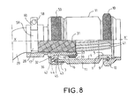
- FIG. 8 shows a cable 29 introduced into the assembled device according to the invention.
- the cables 41 forming the strand have been stripped of their individual shielding and these shields and possibly an outer shielding sheath 31 are folded in a known manner on the front part 35 of the fireplace.
- the folded part 37 is held for example by a ring 39 crimping on the front part 35. If there is an over-armoring, this can be connected to the rear of the chimney. This embodiment avoids a space in the chamber 11 whose diameter can then be reduced.
- the gap between the internal diameter of the chimney and the diameter internal of the chamber results in this case from the need for the diameter internal of the chimney 17 to allow the passage of the strand, and for the internal diameter of the chamber 11 to allow the housing of the part folded down 37 and in this case of the crimping ring 39.
Landscapes
- Details Of Connecting Devices For Male And Female Coupling (AREA)
- Cable Accessories (AREA)
- Installation Of Indoor Wiring (AREA)
- Removal Of Insulation Or Armoring From Wires Or Cables (AREA)
- Manufacturing Of Electric Cables (AREA)
- Insulated Conductors (AREA)
- Multi-Conductor Connections (AREA)
- Shielding Devices Or Components To Electric Or Magnetic Fields (AREA)
Claims (8)
- Vorrichtung, die dazu bestimmt ist, die Abschirmung von Enden (41) einer Litze (29) aus abgeschirmten Kabeln zu gewährleisten, die in einen Abschirmungsmantel eingeführt werden müssen, wobei die Vorrichtung eine Kammer (11) aufweist, die entlang einer axialen Linie XX' der Vorrichtung zwei Enden, ein vorderes Ende in der Nähe der Enden (41) der Kabel und ein hinteres Ende aufweist, das von diesen Enden (41) entfernt ist, wobei eine Innenfläche der Kammer ein Innenvolumen der Kammer abgrenzt, eine Buchse (17), von der wenigstens ein Teil (21) außerhalb der Kammer (11) in der Nähe ihres hinteren Endes liegt, wobei die Buchse (17) eine Innenfläche und eine Außenfläche aufweist, wobei eine Schulter (32) radial an der Außenfläche vorsteht, wobei die Innenfläche der Buchse ein Volumen abgrenzt, das zur Aufnahme eines Teils der Litze (29) bestimmt ist, wobei die Buchse (17) entlang der axialen Linie XX' der Vorrichtung zwei Enden, ein vorderes Ende in der Nähe der Enden (41) des Kabels und ein hinteres, entferntes Ende aufweist, wobei die elektromagnetische Dichtigkeit auf Höhe des hinteren Endes (6) der Kammer (11) durch Mittel (40, 32) sichergestellt ist, die einerseits über den gesamten Umfang der Buchse (17) und andererseits über den gesamten Umfang (2) der Kammer (11) in kontinuierlichem elektrischen Kontakt stehen, wobei die Kontaktmittel (32, 40) zwischen der Buchse und der Kammer zusammen ein Teil bilden, dessen Außenumfang mit wenigstens einem Querschnitt nach einer Ebene, die lokal senkrecht zu der axialen Linie der Vorrichtung liegt, einen größeren Umfang als den Innenumfang eines Querschnitts der Kammer nach der gleichen Ebene hat, dadurch gekennzeichnet, daß die Kontaktmittel Sektorschalen (40) aufweisen, die insgesamt die Form einer flachen Scheibe haben, eine vordere Fläche, eine hintere Fläche, eine innere Seitenfläche und eine äußere Seitenfläche haben, wobei die innere Seitenfläche der so gebildeten Scheibe in elektrischem Kontakt mit der Außenfläche (16) der Buchse (17) steht, wobei wenigstens ein Teil (45) der vorderen Fläche in Anlage an der hinteren Fläche (2) des hinteren Endes (6) der Kammer (11) steht, wobei der Außendurchmesser der Schulter (32) bis auf die Toleranzen höchstens gleich dem Durchmesser des hinteren Teils der Kammer ist und die Schulter (32) wenigstens an einem Teil der hinteren Fläche der Schalen (40) in Anlage gelangt.
- Vorrichtung nach Anspruch 1, dadurch gekennzeichnet, daß wenigstens ein Querschnitt der Kammer (11), der nahe an dem ersten Ende (7) liegt, einen kleineren Innendurchmesser als ein Querschnitt der Innenfläche hat, der nahe an dem zweiten Ende (6) der Kammer (11) liegt.
- Vorrichtung nach Anspruch 1, dadurch gekennzeichnet, daß das hintere Ende (6) der Kammer ein rotationssymmetrischer Zylinder ist.
- Vorrichtung nach einem der vorhergehenden Ansprüche, dadurch gekennzeichnet, daß die Kammer mit einem Außengewinde (3) versehen ist.
- Vorrichtung nach einem der vorhergehenden Ansprüche, dadurch gekennzeichnet, daß die von der Gesamtheit der Schalen (40) gebildete Scheibe einen vorderen Teil hat, von dem wenigstens ein Teil der äußeren Seitenfläche mit der inneren Seitenfläche des hinteren Endes (6) der Kammer in Kontakt steht, um eine Positionierung der Buchse bezüglich der Kammer zu gewährleisten.
- Vorrichtung nach einem der vorhergehenden Ansprüche, dadurch gekennzeichnet, daß die Buchse und die Kammer durch Mittel zusammengehalten werden, die einen nach vorne gerichteten Druck auf einen hinteren Teil der Schulter (32) der Buchse (17) ausüben.
- Vorrichtung nach Anspruch 6, dadurch gekennzeichnet, daß das Mittel zum Ermöglichen der Druckausübung eine Mutter (50) ist, die auf den Gewindeteil (3) der Kammer (11) geschraubt wird.
- Vorrichtung nach einem der vorhergehenden Ansprüche, dadurch gekennzeichnet, daß die Vorrichtung ferner Klemmpratzen (60) aufweist, die im Zusammenwirken mit den Kerben (26, 28) der Buchse das Halten einer Kabellitze (29) ermöglichen.
Applications Claiming Priority (2)
| Application Number | Priority Date | Filing Date | Title |
|---|---|---|---|
| FR9504819A FR2733366B1 (fr) | 1995-04-21 | 1995-04-21 | Dispositif de reprise de blindages de cables |
| FR9504819 | 1995-04-21 |
Publications (2)
| Publication Number | Publication Date |
|---|---|
| EP0739057A1 EP0739057A1 (de) | 1996-10-23 |
| EP0739057B1 true EP0739057B1 (de) | 1999-09-01 |
Family
ID=9478351
Family Applications (1)
| Application Number | Title | Priority Date | Filing Date |
|---|---|---|---|
| EP96400805A Expired - Lifetime EP0739057B1 (de) | 1995-04-21 | 1996-04-16 | Einrichtung zum Anschliessen eines Kabelschirms |
Country Status (7)
| Country | Link |
|---|---|
| US (1) | US5746625A (de) |
| EP (1) | EP0739057B1 (de) |
| JP (1) | JPH08306434A (de) |
| AT (1) | ATE184136T1 (de) |
| DE (1) | DE69604007T2 (de) |
| ES (1) | ES2138300T3 (de) |
| FR (1) | FR2733366B1 (de) |
Families Citing this family (7)
| Publication number | Priority date | Publication date | Assignee | Title |
|---|---|---|---|---|
| FR2767230B1 (fr) * | 1997-08-08 | 1999-11-05 | Socapex Amphenol | Capot pour connecteur electrique ou optique |
| US6042396A (en) * | 1997-10-03 | 2000-03-28 | Yazaki Corporation | Terminal treatment structure of a shield wire |
| US6227881B1 (en) | 1999-12-06 | 2001-05-08 | The Jpm Company | Cable management coupling and shielding interconnect system and method |
| FR2929049B1 (fr) * | 2008-03-19 | 2010-03-12 | Labinal | Procede de reprise du blindage electromagnetique individuel de cables electriques d'un toron sur un connecteur electrique. |
| KR101538806B1 (ko) * | 2009-03-16 | 2015-07-22 | 타이코에이엠피(유) | 차폐용 편조선의 쉘커버 |
| DE102013009184A1 (de) * | 2013-05-31 | 2014-12-04 | Kostal Kontakt Systeme Gmbh | Kontaktelement |
| CN116526222B (zh) * | 2023-06-29 | 2023-09-29 | 杭州海康威视数字技术股份有限公司 | 线缆组件 |
Family Cites Families (8)
| Publication number | Priority date | Publication date | Assignee | Title |
|---|---|---|---|---|
| GB571835A (en) * | 1943-10-14 | 1945-09-11 | Hugh Wood And Company Ltd | An improved cable plug connection |
| US3732526A (en) * | 1971-06-25 | 1973-05-08 | Bendix Corp | Electrical connector with improved cable support |
| US3891294A (en) * | 1974-01-09 | 1975-06-24 | Gen Signal Corp | Cord grip connector |
| USRE31995E (en) * | 1979-07-12 | 1985-10-01 | Automation Industries, Inc. | Enhanced detent guide track with dog-leg |
| GB2060278B (en) * | 1979-10-05 | 1983-04-13 | Victor Products Ltd | Gland for metal sheathed cable |
| JPH0530307Y2 (de) * | 1987-02-12 | 1993-08-03 | ||
| DE4013963A1 (de) * | 1990-04-30 | 1991-10-31 | Gore W L & Ass Gmbh | Metallisches verbindergehaeuse |
| US5246376A (en) * | 1992-04-28 | 1993-09-21 | Raychem Sa | Electrical adaptor |
-
1995
- 1995-04-21 FR FR9504819A patent/FR2733366B1/fr not_active Expired - Fee Related
-
1996
- 1996-04-16 ES ES96400805T patent/ES2138300T3/es not_active Expired - Lifetime
- 1996-04-16 DE DE69604007T patent/DE69604007T2/de not_active Expired - Fee Related
- 1996-04-16 EP EP96400805A patent/EP0739057B1/de not_active Expired - Lifetime
- 1996-04-16 AT AT96400805T patent/ATE184136T1/de not_active IP Right Cessation
- 1996-04-17 US US08/633,357 patent/US5746625A/en not_active Expired - Fee Related
- 1996-04-22 JP JP8122860A patent/JPH08306434A/ja not_active Withdrawn
Also Published As
| Publication number | Publication date |
|---|---|
| DE69604007D1 (de) | 1999-10-07 |
| US5746625A (en) | 1998-05-05 |
| ATE184136T1 (de) | 1999-09-15 |
| DE69604007T2 (de) | 2000-03-23 |
| FR2733366A1 (fr) | 1996-10-25 |
| FR2733366B1 (fr) | 1997-05-23 |
| EP0739057A1 (de) | 1996-10-23 |
| JPH08306434A (ja) | 1996-11-22 |
| ES2138300T3 (es) | 2000-01-01 |
Similar Documents
| Publication | Publication Date | Title |
|---|---|---|
| FR2463526A1 (fr) | Connecteur de cable a armure metallique sous gaine | |
| EP0739057B1 (de) | Einrichtung zum Anschliessen eines Kabelschirms | |
| EP1860672B1 (de) | Stangenbuchsenanordnung, die durch eine Öffnung einer Wand eines Stromwandlers eingebaut werden soll | |
| EP1251617B1 (de) | Kabelabdichtung | |
| EP0246947B1 (de) | Elektrischer Unterwassersteckverbinder | |
| EP0989348B1 (de) | Vorrichtung zum Schnellverbinden von Rohren | |
| FR2772515A1 (fr) | Dispositif de lampe a decharge electrique et prise isolante pour celui-ci | |
| FR2713408A1 (fr) | Connecteur électrique. | |
| EP0450988A1 (de) | Verbinder für Koaxialkabel | |
| EP1400195A1 (de) | Haushaltsgerät aus scharnierartig verbundenen Rostelementen | |
| EP1016171B1 (de) | Anordnung zum verbinden der abschirmung eines gehäuses und eines schirmkabels | |
| EP3878061B1 (de) | Hintere verbindung mit elektromagnetischem schutz | |
| EP2366189A1 (de) | Busbar-muffe mit einem dem verbinder gewidmeten orientierungsmässig justierbaren schutzgehäuse | |
| FR2952467A1 (fr) | Emballage pour le transport et/ou entreposage de matieres radioactives conferant un transfert thermique renforce | |
| EP0763876A1 (de) | Vorrichtung zur Arretierung eines Kabels in einem explosionsgeschützten Gehäuse | |
| FR2759762A1 (fr) | Raccord isolant dielectrique et procede d'assemblage d'un tel raccord | |
| FR2777341A1 (fr) | Dispositif de raccordement instantane pour tuyau | |
| FR2594205A1 (fr) | Raccord terminal de tuyau souple | |
| EP2237385B1 (de) | Kabeldurchführungsgarnitur | |
| FR2655122A1 (fr) | Joint d'etancheite pour connecteur electrique, et connecteur qui en est equipe. | |
| FR2658583A1 (fr) | Dispositif de raccordement et d'etancheite pour deux tuyaux montes bout a bout. | |
| EP3867557B1 (de) | Anordnung mit einer rohrleitung und einer verbindungsvorrichtung zum verbinden eines rohres mit einer wand der rohrleitung | |
| EP3602696A1 (de) | Rundsteckverbinder mit dichtungsdurchgangsöse und haltering | |
| EP0599673A1 (de) | Verbinderhülse für abgedichtete Durchführung und dazugehörige Anordnung | |
| FR2740914A1 (fr) | Connecteur pour cable blinde |
Legal Events
| Date | Code | Title | Description |
|---|---|---|---|
| PUAI | Public reference made under article 153(3) epc to a published international application that has entered the european phase |
Free format text: ORIGINAL CODE: 0009012 |
|
| AK | Designated contracting states |
Kind code of ref document: A1 Designated state(s): AT BE CH DE DK ES FR GB IT LI LU NL SE |
|
| 17P | Request for examination filed |
Effective date: 19970422 |
|
| 17Q | First examination report despatched |
Effective date: 19980529 |
|
| GRAG | Despatch of communication of intention to grant |
Free format text: ORIGINAL CODE: EPIDOS AGRA |
|
| GRAG | Despatch of communication of intention to grant |
Free format text: ORIGINAL CODE: EPIDOS AGRA |
|
| GRAH | Despatch of communication of intention to grant a patent |
Free format text: ORIGINAL CODE: EPIDOS IGRA |
|
| GRAH | Despatch of communication of intention to grant a patent |
Free format text: ORIGINAL CODE: EPIDOS IGRA |
|
| GRAA | (expected) grant |
Free format text: ORIGINAL CODE: 0009210 |
|
| AK | Designated contracting states |
Kind code of ref document: B1 Designated state(s): AT BE CH DE DK ES FR GB IT LI LU NL SE |
|
| PG25 | Lapsed in a contracting state [announced via postgrant information from national office to epo] |
Ref country code: AT Free format text: LAPSE BECAUSE OF FAILURE TO SUBMIT A TRANSLATION OF THE DESCRIPTION OR TO PAY THE FEE WITHIN THE PRESCRIBED TIME-LIMIT Effective date: 19990901 |
|
| REF | Corresponds to: |
Ref document number: 184136 Country of ref document: AT Date of ref document: 19990915 Kind code of ref document: T |
|
| REG | Reference to a national code |
Ref country code: CH Ref legal event code: EP |
|
| ITF | It: translation for a ep patent filed | ||
| REF | Corresponds to: |
Ref document number: 69604007 Country of ref document: DE Date of ref document: 19991007 |
|
| GBT | Gb: translation of ep patent filed (gb section 77(6)(a)/1977) |
Effective date: 19991105 |
|
| PG25 | Lapsed in a contracting state [announced via postgrant information from national office to epo] |
Ref country code: DK Free format text: LAPSE BECAUSE OF FAILURE TO SUBMIT A TRANSLATION OF THE DESCRIPTION OR TO PAY THE FEE WITHIN THE PRESCRIBED TIME-LIMIT Effective date: 19991201 |
|
| REG | Reference to a national code |
Ref country code: ES Ref legal event code: FG2A Ref document number: 2138300 Country of ref document: ES Kind code of ref document: T3 |
|
| PGFP | Annual fee paid to national office [announced via postgrant information from national office to epo] |
Ref country code: SE Payment date: 20000316 Year of fee payment: 5 |
|
| PGFP | Annual fee paid to national office [announced via postgrant information from national office to epo] |
Ref country code: BE Payment date: 20000406 Year of fee payment: 5 |
|
| PGFP | Annual fee paid to national office [announced via postgrant information from national office to epo] |
Ref country code: ES Payment date: 20000407 Year of fee payment: 5 |
|
| PG25 | Lapsed in a contracting state [announced via postgrant information from national office to epo] |
Ref country code: LU Free format text: LAPSE BECAUSE OF NON-PAYMENT OF DUE FEES Effective date: 20000416 |
|
| PG25 | Lapsed in a contracting state [announced via postgrant information from national office to epo] |
Ref country code: LI Free format text: LAPSE BECAUSE OF NON-PAYMENT OF DUE FEES Effective date: 20000430 Ref country code: CH Free format text: LAPSE BECAUSE OF NON-PAYMENT OF DUE FEES Effective date: 20000430 |
|
| PLBE | No opposition filed within time limit |
Free format text: ORIGINAL CODE: 0009261 |
|
| STAA | Information on the status of an ep patent application or granted ep patent |
Free format text: STATUS: NO OPPOSITION FILED WITHIN TIME LIMIT |
|
| 26N | No opposition filed | ||
| REG | Reference to a national code |
Ref country code: CH Ref legal event code: PL |
|
| PG25 | Lapsed in a contracting state [announced via postgrant information from national office to epo] |
Ref country code: SE Free format text: LAPSE BECAUSE OF NON-PAYMENT OF DUE FEES Effective date: 20010417 Ref country code: ES Free format text: LAPSE BECAUSE OF NON-PAYMENT OF DUE FEES Effective date: 20010417 |
|
| PG25 | Lapsed in a contracting state [announced via postgrant information from national office to epo] |
Ref country code: BE Free format text: LAPSE BECAUSE OF NON-PAYMENT OF DUE FEES Effective date: 20010430 |
|
| BERE | Be: lapsed |
Owner name: THOMSON CSF Effective date: 20010430 |
|
| EUG | Se: european patent has lapsed |
Ref document number: 96400805.6 |
|
| REG | Reference to a national code |
Ref country code: GB Ref legal event code: IF02 |
|
| PGFP | Annual fee paid to national office [announced via postgrant information from national office to epo] |
Ref country code: DE Payment date: 20020322 Year of fee payment: 7 |
|
| PGFP | Annual fee paid to national office [announced via postgrant information from national office to epo] |
Ref country code: GB Payment date: 20020325 Year of fee payment: 7 |
|
| PGFP | Annual fee paid to national office [announced via postgrant information from national office to epo] |
Ref country code: NL Payment date: 20020408 Year of fee payment: 7 |
|
| PGFP | Annual fee paid to national office [announced via postgrant information from national office to epo] |
Ref country code: FR Payment date: 20020416 Year of fee payment: 7 |
|
| REG | Reference to a national code |
Ref country code: FR Ref legal event code: CD |
|
| REG | Reference to a national code |
Ref country code: ES Ref legal event code: FD2A Effective date: 20030203 |
|
| PG25 | Lapsed in a contracting state [announced via postgrant information from national office to epo] |
Ref country code: GB Free format text: LAPSE BECAUSE OF NON-PAYMENT OF DUE FEES Effective date: 20030416 |
|
| PG25 | Lapsed in a contracting state [announced via postgrant information from national office to epo] |
Ref country code: NL Free format text: LAPSE BECAUSE OF NON-PAYMENT OF DUE FEES Effective date: 20031101 Ref country code: DE Free format text: LAPSE BECAUSE OF NON-PAYMENT OF DUE FEES Effective date: 20031101 |
|
| NLV4 | Nl: lapsed or anulled due to non-payment of the annual fee |
Effective date: 20031101 |
|
| GBPC | Gb: european patent ceased through non-payment of renewal fee |
Effective date: 20030416 |
|
| PG25 | Lapsed in a contracting state [announced via postgrant information from national office to epo] |
Ref country code: FR Free format text: LAPSE BECAUSE OF NON-PAYMENT OF DUE FEES Effective date: 20031231 |
|
| REG | Reference to a national code |
Ref country code: FR Ref legal event code: ST |
|
| PG25 | Lapsed in a contracting state [announced via postgrant information from national office to epo] |
Ref country code: IT Free format text: LAPSE BECAUSE OF NON-PAYMENT OF DUE FEES;WARNING: LAPSES OF ITALIAN PATENTS WITH EFFECTIVE DATE BEFORE 2007 MAY HAVE OCCURRED AT ANY TIME BEFORE 2007. THE CORRECT EFFECTIVE DATE MAY BE DIFFERENT FROM THE ONE RECORDED. Effective date: 20050416 |