EP0739059A2 - Coaxial connector - Google Patents
Coaxial connector Download PDFInfo
- Publication number
- EP0739059A2 EP0739059A2 EP96400826A EP96400826A EP0739059A2 EP 0739059 A2 EP0739059 A2 EP 0739059A2 EP 96400826 A EP96400826 A EP 96400826A EP 96400826 A EP96400826 A EP 96400826A EP 0739059 A2 EP0739059 A2 EP 0739059A2
- Authority
- EP
- European Patent Office
- Prior art keywords
- bushing
- socket
- housing
- coaxial connector
- cover
- Prior art date
- Legal status (The legal status is an assumption and is not a legal conclusion. Google has not performed a legal analysis and makes no representation as to the accuracy of the status listed.)
- Granted
Links
Images


Classifications
-
- H—ELECTRICITY
- H01—ELECTRIC ELEMENTS
- H01R—ELECTRICALLY-CONDUCTIVE CONNECTIONS; STRUCTURAL ASSOCIATIONS OF A PLURALITY OF MUTUALLY-INSULATED ELECTRICAL CONNECTING ELEMENTS; COUPLING DEVICES; CURRENT COLLECTORS
- H01R9/00—Structural associations of a plurality of mutually-insulated electrical connecting elements, e.g. terminal strips or terminal blocks; Terminals or binding posts mounted upon a base or in a case; Bases therefor
- H01R9/03—Connectors arranged to contact a plurality of the conductors of a multiconductor cable, e.g. tapping connections
- H01R9/05—Connectors arranged to contact a plurality of the conductors of a multiconductor cable, e.g. tapping connections for coaxial cables
- H01R9/0518—Connection to outer conductor by crimping or by crimping ferrule
-
- H—ELECTRICITY
- H01—ELECTRIC ELEMENTS
- H01R—ELECTRICALLY-CONDUCTIVE CONNECTIONS; STRUCTURAL ASSOCIATIONS OF A PLURALITY OF MUTUALLY-INSULATED ELECTRICAL CONNECTING ELEMENTS; COUPLING DEVICES; CURRENT COLLECTORS
- H01R24/00—Two-part coupling devices, or either of their cooperating parts, characterised by their overall structure
- H01R24/38—Two-part coupling devices, or either of their cooperating parts, characterised by their overall structure having concentrically or coaxially arranged contacts
- H01R24/40—Two-part coupling devices, or either of their cooperating parts, characterised by their overall structure having concentrically or coaxially arranged contacts specially adapted for high frequency
- H01R24/42—Two-part coupling devices, or either of their cooperating parts, characterised by their overall structure having concentrically or coaxially arranged contacts specially adapted for high frequency comprising impedance matching means or electrical components, e.g. filters or switches
- H01R24/44—Two-part coupling devices, or either of their cooperating parts, characterised by their overall structure having concentrically or coaxially arranged contacts specially adapted for high frequency comprising impedance matching means or electrical components, e.g. filters or switches comprising impedance matching means
-
- H—ELECTRICITY
- H01—ELECTRIC ELEMENTS
- H01R—ELECTRICALLY-CONDUCTIVE CONNECTIONS; STRUCTURAL ASSOCIATIONS OF A PLURALITY OF MUTUALLY-INSULATED ELECTRICAL CONNECTING ELEMENTS; COUPLING DEVICES; CURRENT COLLECTORS
- H01R2103/00—Two poles
Definitions
- the present invention broadly relates to a coaxial connector and, more particularly, to a small coaxial connector used for connecting a coaxial cable to a receptacle, for example, in a portable communication device.
- the conventional coaxial connector comprises a metallic housing 71, a socket 73, and a bushing 72.
- the housing 71 includes a cylindrical portion 74 which comes into contact with the outer conductor portion of a receptacle (not shown in Fig. 7), a cover 75 for covering an upper opening of the cylindrical portion 74, and a crimping portion 76 for gripping an outer conductor portion 78a of a coaxial cable 77.
- the insulating bushing 72 is accommodated in the cylindrical portion 74 of the housing 71, and the socket 73 which comes into contact with the central conductor of the receptacle (not shown in Figure 7) is held by the bushing 72.
- the central conductor portion 78b of the coaxial cable 77 is connected to the socket 73.
- Fig. 8 is a perspective view of the bushing 72 of Fig. 7, in which a socket 73 is fitted into a hole 80 formed in the bushing 72 at its central axis. As illustrated in Fig. 7, a plurality of pawls 79 extend radially outward from the socket 73, which engage the bushing 72 to prevent the socket 73 from being removed from the hole 80.
- the front end of the socket 73 has a tendency to deform due to external forces exerted thereto during mounting of the coaxial connector into the receptacle or the like.
- This problem might be overcome by increasing the height of the bushing 72 so that the socket 73 does not protrude from the bottom face of the bushing 72.
- the lower portion of the bushing 72 is tapered to allow the cylindrical portion 74 of the housing 71 to be pressed inward in order to let the cylindrical portion 74 deform, as it comes into contact with the outer conductor portion of the receptacle to be mounted therein. Accordingly, when the height of the bushing 72 is increased, as mentioned above, the lower portion of the bushing 72 becomes thinner, thus making it difficult to form the bushing 72 when producing a smaller coaxial connector.
- an object of the present invention is to provide a coaxial connector in which the bushing can be easily mounted to the housing.
- Another object of the present invention is to provide a coaxial connector which makes it possible to eliminate the problem of poor pressure resistance and characteristic impedance resulting from socket displacement.
- a further object of the present invention is to provide a coaxial connector which makes it possible to prevent deformation of the front end of the socket.
- projections are formed along the outer periphery of the bushing, and cutouts for engaging the projections of the bushings are formed along the periphery of the cylindrical portion of the housing.
- the projections of the bushing engage the cutouts of the housing to thereby position the bushing around the axis.
- the bushing in order to prevent displacement of the mounting position of the socket to the bushing, is provided with a cover which covers holes in the bushing, while the socket is being held by the bushing.
- the cover of the bushing covers the upper portion of the socket in order to hold the socket in position.
- the front end of the bushing in the direction of which the bushing is inserted into the housing is such as to extend up to the region around the end of the socket.
- the outer periphery of the front end can be made smaller than the outer periphery of the base portion to form a tapered intermediate portion between the front end of the bushing and the base portion. Since only the intermediate portion of the bushing is tapered, the length of the bushing in the axial direction can be made long, without having to make the lower end of the bushing extremely thin, so that it is possible to limit the projection amount of the socket from the bushing even for a small coaxial connector.
- the projections of the bushing engage the cutouts of the housing to thereby position the bushing around the axis, so that the bushing can be mounted to the housing more easily.
- the cover of the bushing covers the upper portion of the socket in the bushing in order to hold the socket in position, thus preventing displacement of the mounting position of the socket to the bushing.
- the projection amount of the socket from the bushing can be limited in length even for a small coaxial connector, without having to considerably decrease the thickness of the lower end of the bushing when it is made long in the axial direction, so that it is possible to prevent deformation of the front end of the socket.
- Fig. 1 is an exploded perspective view of the component parts of a coaxial connector of a first embodiment of the present invention.
- Figs. 2a - 2e illustrate the construction of a bushing used in the coaxial connector of the first embodiment of the present invention shown in Fig. 1.
- Figs. 3a - 3c illustrate the construction of the bushing used in the coaxial connector of the first embodiment of the present invention shown in Fig. 1.
- Fig. 4 is a perspective view of a receptacle in relation to the coaxial connector.
- Figs. 5a - 5c are cross sectional views of the coaxial connector which is being mounted into the receptacle.
- Fig. 6 is a perspective view of a form of the bushing used in a coaxial connector of a second embodiment of the present invention.
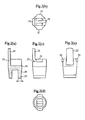
- Fig. 7 is a cross-sectional view of the construction of a conventional coaxial connector.
- Fig. 8 is a perspective view of the construction of a bushing used in the conventional coaxial connector.
- Fig. 1 is an exploded perspective view of the component parts of a coaxial connector.
- reference numeral 1 denotes a metallic housing formed by punching, and bending and holding a metal sheet
- reference numeral 2 denotes a bushing made of insulating synthetic resin
- reference numeral 3 denotes a socket formed by punching, and bending and folding a metal sheet.
- the housing 1 includes a cylindrical portion 14 which comes into contact with the outer conductor portion of a receptacle (not shown in Fig. 1), a cover 12 for covering the upper opening of the cylindrical portion 14, and crimping portions 13a, 13b, and 13c for crimping to a coaxial cable to grip the cable.
- Cutouts 15, 15 are formed in the upper periphery of the cylindrical portion 14. Additional cutouts are formed in the lower periphery of the cylindrical portion 14 to permit the cylindrical portion 14 to be pressed inward when it is inserted into a receptacle. Protrusions 21, 21 which engage in the cutouts 15, 15 of the housing 1 are provided at the outer periphery of the bushing 2.
- cylindrical is to be given its mathematical definition as a surface generated by a straight line which moves so that it always intersects a given plane (directrix) and remains parallel to a fixed line that intersects the plane of the directrix. This includes circular cylinders, quadric cylinders, elliptic cylinders, parabolic cylinders, hyperbolic cylinders, as well as cylinders whose directrix and right sections are polygons.
- the bushing 2 has a cover 22 for covering central holes 26 in the bushing 2 for holding the socket 3.
- the bushing 2 has a front end portion 23 in the direction of which the bushing 2 is inserted into the housing 1 with an outer periphery thereof being smaller than the outer periphery of a central base portion 25 in the bushing 2, thereby forming a tapering intermediate portion 24 located between the base portion 25 and the front end portion 23.
- the socket 3 is constructed so as to allow for insertion of a center conductor portion 41 of a coaxial cable 4 into it.
- Figs. 2a, 2b, 2c, 2d, and 2e are illustrations of the construction of the bushing 2 of Fig. 1. More specifically, Fig. 2a is a cross-sectional view of the construction in a plane passing through the central axis of the cover 22 and the bushing 2. Figs. 2b, 2c, 2d, and 2e are a top view, a front view, a bottom view, and a right side view of the construction, respectively. As illustrated in Figs. 2a to 2e, a wedge-shaped cutout 27 is formed in the base portion of the cover 22 so as to allow the cover 22 to bend at the wedge-shaped cutout 27.
- Socket 3 includes a bridging portion connecting its electrodes together. When the electrodes of socket 3 are inserted into respective holes 26 of the bushing 2, this bridging portion of the socket 3 overlies the band of material between the holes 26.
- Figs. 3a, 3b, and 3c are a top view, a front view, and a right side view of the construction of the bushing 2, with the holes being covered by the cover 22.
- the upper side of the bushing 2 is made substantially level or co-planar when the cover 22 is bent over to cover the holes 26, and the cover 12 of the housing 1 covers the upper portion of the bushing 2.
- Fig. 4 is a perspective view of a coaxial connector having a coaxial cable mounted thereto in relation to a receptacle.
- reference numeral 5 denotes a receptacle which is mounted onto a circuit substrate or the like.
- the receptacle 5 includes a central conductor portion 51, an outer conductor portion 52, and a leading terminal 53 of the central conductor portion 51.
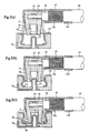
- Figs. 5a, 5b, and 5c are cross-sectional views of the coaxial cable being mounted to the coaxial connector and the coaxial connector being mounted into the receptacle.
- reference numeral 41 denotes a central conductor portion of the coaxial cable
- reference numeral 42 denotes an insulation portion
- reference numeral 43 denotes an outer conductor portion
- reference numeral 44 denotes an outer sheath.
- the central conductor portion 78b of the coaxial cable and the outer conductor portion 43 of the coaxial cable are electrically connected to the socket 73 and the crimping portion 13a of the housing 1, respectively.
- the cylindrical portion 14 of the housing 1 is pressed inward, as shown in Figs. 5a and 5b. During the insertion, the bushing 2 does not interfere with the socket 3 because the bushing 2 has a tapered portion 24.
- the coaxial connector is further pushed into the receptacle 5, the cylindrical portion 14 of the housing 1 widens due to its resiliency, resulting in engagement with the outer conductor portion 52 of the receptacle 5. When this occurs, the socket 3 comes into contact with the central conductor portion 51 of the receptacle 5.
- Fig. 6 illustrates an example of another bushing having a different form.
- the bushing 2 illustrated in Fig. 1 or the like has two projections 21, 21 which are disposed opposite each other with respect to a central axis being the central line of the housing 1, when the two projections 21, 21 are engaging the cutouts 15, 15 of the housing 1.
- the bushing 2 of Fig. 6, only needs to have at least one projection portion 21.
- the cover 22 may be formed to have cylindrical sides and so as to cover the entire upper portion of the bushing 2, as illustrated in Fig. 6, although in the bushing 2 of Fig. 1 the cover 22 was formed so as to cover only the holes 26 of the bushing 2.
- the projections 21, 21 of the bushing 2 engage the cutouts 15, 15 of the housing 1 to thereby position the bushing 2 around the axis, so that the bushing 2 can be mounted to the housing 1 far more easily.
- the cover 22 of the bushing 2 covers the upper portion of the socket 3 in order to hold the socket 3 in position, thereby preventing poor pressure resistance and characteristic impedance due to displacement of the mounting position of the socket 3 to the bushing 2.
- the coaxial connector of the third aspect of the present invention since only the intermediate portion 24 of the bushing 2 is tapered, it is possible to limit the amount of projection of the socket 3 from the bushing 2 even for a small coaxial connector, without having to considerably decrease the thickness of the lower end of the bushing 2 when it is made long along the axial direction, so that deformation of the front end of the socket 3 can be prevented.
Landscapes
- Coupling Device And Connection With Printed Circuit (AREA)
Abstract
Description
- The present invention broadly relates to a coaxial connector and, more particularly, to a small coaxial connector used for connecting a coaxial cable to a receptacle, for example, in a portable communication device.
- A description will now be given of the construction of a conventional coaxial connector, with reference to Figs. 7 and 8.
- Referring to Fig. 7, the conventional coaxial connector comprises a
metallic housing 71, asocket 73, and abushing 72. Thehousing 71 includes acylindrical portion 74 which comes into contact with the outer conductor portion of a receptacle (not shown in Fig. 7), acover 75 for covering an upper opening of thecylindrical portion 74, and a crimpingportion 76 for gripping anouter conductor portion 78a of acoaxial cable 77. Theinsulating bushing 72 is accommodated in thecylindrical portion 74 of thehousing 71, and thesocket 73 which comes into contact with the central conductor of the receptacle (not shown in Figure 7) is held by thebushing 72. Thecentral conductor portion 78b of thecoaxial cable 77 is connected to thesocket 73. - Fig. 8 is a perspective view of the bushing 72 of Fig. 7, in which a
socket 73 is fitted into ahole 80 formed in thebushing 72 at its central axis. As illustrated in Fig. 7, a plurality ofpawls 79 extend radially outward from thesocket 73, which engage thebushing 72 to prevent thesocket 73 from being removed from thehole 80. - However, such a conventional coaxial connector has the following problems. A cutout needs to be formed in the
bushing 72 which is mounted into thehousing 71 in order to insert the front end of the coaxial cable, as illustrated in Fig. 8. The coaxial cable must be mounted in thehousing 71, with the cutout facing the direction of the extension of the coaxial cable. This, however, is difficult to accomplish because thebushing 72 tends to rotate around the axis. - Carelessness when fitting the
socket 73 into thebushing 72 or when mounting a completed coaxial connector into the receptacle causes an abnormally high upward stress to be exerted onto thesocket 73, displacing thesocket 73 upward from the predetermined position. This results in a smaller distance between thesocket 73 and thecover 75 of thehousing 71. A smaller distance may lead to poor pressure resistance and characteristic impedance. - In addition, since the
socket 73 projects below from the bottom face of thebushing 72, the front end of thesocket 73 has a tendency to deform due to external forces exerted thereto during mounting of the coaxial connector into the receptacle or the like. This problem might be overcome by increasing the height of thebushing 72 so that thesocket 73 does not protrude from the bottom face of thebushing 72. This, however, cannot be done because the lower portion of thebushing 72 is tapered to allow thecylindrical portion 74 of thehousing 71 to be pressed inward in order to let thecylindrical portion 74 deform, as it comes into contact with the outer conductor portion of the receptacle to be mounted therein. Accordingly, when the height of thebushing 72 is increased, as mentioned above, the lower portion of thebushing 72 becomes thinner, thus making it difficult to form thebushing 72 when producing a smaller coaxial connector. - Accordingly, an object of the present invention is to provide a coaxial connector in which the bushing can be easily mounted to the housing.
- Another object of the present invention is to provide a coaxial connector which makes it possible to eliminate the problem of poor pressure resistance and characteristic impedance resulting from socket displacement.
- A further object of the present invention is to provide a coaxial connector which makes it possible to prevent deformation of the front end of the socket.
- In a first aspect of the present invention, in order to facilitate positioning around the axis when mounting the bushing to the housing, projections are formed along the outer periphery of the bushing, and cutouts for engaging the projections of the bushings are formed along the periphery of the cylindrical portion of the housing. When the bushing is being mounted to the housing, the projections of the bushing engage the cutouts of the housing to thereby position the bushing around the axis.
- In a second aspect of the present invention, in order to prevent displacement of the mounting position of the socket to the bushing, the bushing is provided with a cover which covers holes in the bushing, while the socket is being held by the bushing. The cover of the bushing covers the upper portion of the socket in order to hold the socket in position.
- To limit the amount of projection of the socket from the bushing, in a third aspect of the present invention, the front end of the bushing in the direction of which the bushing is inserted into the housing is such as to extend up to the region around the end of the socket. In addition, the outer periphery of the front end can be made smaller than the outer periphery of the base portion to form a tapered intermediate portion between the front end of the bushing and the base portion. Since only the intermediate portion of the bushing is tapered, the length of the bushing in the axial direction can be made long, without having to make the lower end of the bushing extremely thin, so that it is possible to limit the projection amount of the socket from the bushing even for a small coaxial connector.
- According to the coaxial connector of the first aspect of the present invention, when mounting a bushing to a housing, the projections of the bushing engage the cutouts of the housing to thereby position the bushing around the axis, so that the bushing can be mounted to the housing more easily.
- According to the coaxial connector of the second aspect of the present invention, the cover of the bushing covers the upper portion of the socket in the bushing in order to hold the socket in position, thus preventing displacement of the mounting position of the socket to the bushing.
- According to the coaxial connector of the third aspect of the present invention, since only the intermediate portion of the bushing is tapered, the projection amount of the socket from the bushing can be limited in length even for a small coaxial connector, without having to considerably decrease the thickness of the lower end of the bushing when it is made long in the axial direction, so that it is possible to prevent deformation of the front end of the socket.
- Fig. 1 is an exploded perspective view of the component parts of a coaxial connector of a first embodiment of the present invention.
- Figs. 2a - 2e illustrate the construction of a bushing used in the coaxial connector of the first embodiment of the present invention shown in Fig. 1.
- Figs. 3a - 3c illustrate the construction of the bushing used in the coaxial connector of the first embodiment of the present invention shown in Fig. 1.
- Fig. 4 is a perspective view of a receptacle in relation to the coaxial connector.
- Figs. 5a - 5c are cross sectional views of the coaxial connector which is being mounted into the receptacle.
- Fig. 6 is a perspective view of a form of the bushing used in a coaxial connector of a second embodiment of the present invention.
- Fig. 7 is a cross-sectional view of the construction of a conventional coaxial connector.
- Fig. 8 is a perspective view of the construction of a bushing used in the conventional coaxial connector.
- A description will now be given of the constructions of the coaxial connectors of the preferred embodiments of the present invention, with reference to Figs. 1 to 6.
- Fig. 1 is an exploded perspective view of the component parts of a coaxial connector. Referring to Fig. 1, reference numeral 1 denotes a metallic housing formed by punching, and bending and holding a metal sheet;
reference numeral 2 denotes a bushing made of insulating synthetic resin; andreference numeral 3 denotes a socket formed by punching, and bending and folding a metal sheet. The housing 1 includes acylindrical portion 14 which comes into contact with the outer conductor portion of a receptacle (not shown in Fig. 1), acover 12 for covering the upper opening of thecylindrical portion 14, and crimpingportions Cutouts cylindrical portion 14. Additional cutouts are formed in the lower periphery of thecylindrical portion 14 to permit thecylindrical portion 14 to be pressed inward when it is inserted into a receptacle.Protrusions cutouts bushing 2. - As used herein, "cylindrical" is to be given its mathematical definition as a surface generated by a straight line which moves so that it always intersects a given plane (directrix) and remains parallel to a fixed line that intersects the plane of the directrix. This includes circular cylinders, quadric cylinders, elliptic cylinders, parabolic cylinders, hyperbolic cylinders, as well as cylinders whose directrix and right sections are polygons.
- In addition, the
bushing 2 has acover 22 for coveringcentral holes 26 in thebushing 2 for holding thesocket 3. Further, thebushing 2 has afront end portion 23 in the direction of which thebushing 2 is inserted into the housing 1 with an outer periphery thereof being smaller than the outer periphery of acentral base portion 25 in thebushing 2, thereby forming a taperingintermediate portion 24 located between thebase portion 25 and thefront end portion 23. Thesocket 3 is constructed so as to allow for insertion of acenter conductor portion 41 of a coaxial cable 4 into it. - Figs. 2a, 2b, 2c, 2d, and 2e are illustrations of the construction of the
bushing 2 of Fig. 1. More specifically, Fig. 2a is a cross-sectional view of the construction in a plane passing through the central axis of thecover 22 and thebushing 2. Figs. 2b, 2c, 2d, and 2e are a top view, a front view, a bottom view, and a right side view of the construction, respectively. As illustrated in Figs. 2a to 2e, a wedge-shapedcutout 27 is formed in the base portion of thecover 22 so as to allow thecover 22 to bend at the wedge-shapedcutout 27. Twoholes 26, with a band of material between them, are provided in the central part of thebushing 2 for insertion of respective electrodes of thesocket 3 of Fig. 1.Socket 3 includes a bridging portion connecting its electrodes together. When the electrodes ofsocket 3 are inserted intorespective holes 26 of thebushing 2, this bridging portion of thesocket 3 overlies the band of material between theholes 26. - Figs. 3a, 3b, and 3c are a top view, a front view, and a right side view of the construction of the
bushing 2, with the holes being covered by thecover 22. As illustrated in the figures, the upper side of thebushing 2 is made substantially level or co-planar when thecover 22 is bent over to cover theholes 26, and thecover 12 of the housing 1 covers the upper portion of thebushing 2. - Fig. 4 is a perspective view of a coaxial connector having a coaxial cable mounted thereto in relation to a receptacle. Referring to Fig. 4, reference numeral 5 denotes a receptacle which is mounted onto a circuit substrate or the like. The receptacle 5 includes a
central conductor portion 51, anouter conductor portion 52, and a leadingterminal 53 of thecentral conductor portion 51. - Figs. 5a, 5b, and 5c are cross-sectional views of the coaxial cable being mounted to the coaxial connector and the coaxial connector being mounted into the receptacle. Referring to the figures,
reference numeral 41 denotes a central conductor portion of the coaxial cable;reference numeral 42 denotes an insulation portion;reference numeral 43 denotes an outer conductor portion; andreference numeral 44 denotes an outer sheath. As illustrated in the figures, thecentral conductor portion 78b of the coaxial cable and theouter conductor portion 43 of the coaxial cable are electrically connected to thesocket 73 and the crimpingportion 13a of the housing 1, respectively. - In inserting a coaxial connector with such a coaxial cable connected thereto into the receptacle 5, the
cylindrical portion 14 of the housing 1 is pressed inward, as shown in Figs. 5a and 5b. During the insertion, thebushing 2 does not interfere with thesocket 3 because thebushing 2 has a taperedportion 24. When the coaxial connector is further pushed into the receptacle 5, thecylindrical portion 14 of the housing 1 widens due to its resiliency, resulting in engagement with theouter conductor portion 52 of the receptacle 5. When this occurs, thesocket 3 comes into contact with thecentral conductor portion 51 of the receptacle 5. - Fig. 6 illustrates an example of another bushing having a different form. As described above, the
bushing 2 illustrated in Fig. 1 or the like has twoprojections projections cutouts bushing 2 of Fig. 6, however, only needs to have at least oneprojection portion 21. In addition, thecover 22 may be formed to have cylindrical sides and so as to cover the entire upper portion of thebushing 2, as illustrated in Fig. 6, although in thebushing 2 of Fig. 1 thecover 22 was formed so as to cover only theholes 26 of thebushing 2. - According to the coaxial connector of the first aspect of the present invention, when mounting the
bushing 2 to the housing 1, theprojections bushing 2 engage thecutouts bushing 2 around the axis, so that thebushing 2 can be mounted to the housing 1 far more easily. - According to the coaxial connector of the second aspect of the present invention, the
cover 22 of thebushing 2 covers the upper portion of thesocket 3 in order to hold thesocket 3 in position, thereby preventing poor pressure resistance and characteristic impedance due to displacement of the mounting position of thesocket 3 to thebushing 2. - According to the coaxial connector of the third aspect of the present invention, since only the
intermediate portion 24 of thebushing 2 is tapered, it is possible to limit the amount of projection of thesocket 3 from thebushing 2 even for a small coaxial connector, without having to considerably decrease the thickness of the lower end of thebushing 2 when it is made long along the axial direction, so that deformation of the front end of thesocket 3 can be prevented. - The present invention has been described by way of exemplary embodiments to which the present invention is not limited. The scope of the invention is to be determined by reference to the claims appended hereto.
Claims (10)
- A coaxial connector comprising:a metallic housing (1) including a cylindrical portion (14) which comes into contact with an outer conductor portion of a receptacle, a cover (12) for covering an upper opening of said cylindrical portion, and a crimping portion (13) for gripping at least an outer conductor portion of a coaxial cable;a socket (3) for electrically connecting to a central conductor portion of said coaxial cable and which comes into contact with a central conductor portion of said receptacle; andan insulating bushing (2) for holding said socket (3) at a central axis of said bushing, said bushing being mounted into said cylindrical portion (14) of said housing;wherein at least one projection (21) is formed along an outer periphery of said bushing, and at least one cutout (15) for engaging said at least one projection is formed along a periphery of said cylindrical portion of said housing (1).
- A coaxial connector comprising:a metallic housing (1) including a cylindrical portion (14) which comes into contact with an outer conductor portion of a receptacle, a cover (12) for covering an upper opening of said cylindrical portion, and a crimping portion (13) for gripping at least an outer conductor portion of a coaxial cable;a socket (3) for electrical connecting to a central conductor portion of said coaxial cable and which comes into contact with a central conductor portion of said receptacle; andan insulating bushing (2) having holes (26) for holding said socket (3) at a central axis of said bushing, said bushing being mounted into said cylindrical portion (14) of said housing;wherein said bushing (2) has a cover (22) for covering said holes (26).
- A coaxial connector comprising:a metallic housing (1) including a cylindrical portion (14) which comes into contact with an outer conductor portion of a receptacle, a cover (12) for covering an upper opening of said cylindrical portion (14), and a crimping portion (13) for gripping at least an outer conductor portion of a coaxial cable;a socket (3) for electrically connecting to a central conductor portion of said coaxial cable and which comes into contact with a central conductor portion of said receptacle; andan insulating bushing (2) for holding said socket (3) at a central axis of said insulating bushing, said bushing being mounted into said cylindrical portion (14) of said housing;wherein a front end (23) of said bushing (2) in a direction in which said bushing is inserted into said housing (1) extends up to a region around an end of said socket (3), and an outer periphery of said front end (23) is smaller than an outer periphery of a base portion (25) of said cylindrical portion of said housing, a tapered intermediate portion (24) interconnecting said front end (23) and said base portion (25) of said bushing.
- A coaxial connector according to claim 2 or 3, wherein at least one projection (21) is formed along an outer periphery of said bushing, and at least one cutout (15) for engaging said at least one projection is formed along a periphery of said cylindrical portion of said housing (1).
- A coaxial connector according to claim 1 or 4, wherein said bushing (2) has two projections (21) formed along said outer periphery of said bushing, and said cylindrical portion (14) has two cutouts (15) for engaging said two projections formed along said periphery of said cylindrical portion of said housing.
- A coaxial connector according to claim 1 or 3, wherein said bushing has holes (26) for holding said socket (3) at said central axis of said bushing (2) and has a cover (22) for covering said holes in said bushing.
- A coaxial connector according to claim 2 or 6, wherein said cover (22) has parallel sides and, when covering said holes (26) in said bushing, said cover is co-planar to a top surface of the outer periphery of said bushing.
- A coaxial connector according to claim 7, wherein said cover (22) includes a wedge-shaped cutout (27) in a base portion of said cover.
- A coaxial connector according to claim 2 or 6, wherein said cover (22) has cylindrical sides and, when covering said holes (26) in said bushing, covers a top surface of the outer periphery of said bushing.
- A coaxial connector according to claim 1 or 2, wherein a front end of said bushing (2) in a direction in which said bushing is inserted into said housing (1) extends up to a region around an end of said socket (3), and an outer periphery of said front end (23) is smaller than an outer periphery of a base portion (25) of said cylindrical portion of said housing, a tapered intermediate portion (24) interconnecting said front end (23) and said base portion (25) of said bushing.
Applications Claiming Priority (3)
| Application Number | Priority Date | Filing Date | Title |
|---|---|---|---|
| JP9246495 | 1995-04-18 | ||
| JP07092464A JP3120692B2 (en) | 1995-04-18 | 1995-04-18 | Coaxial connector |
| JP92464/95 | 1995-04-18 |
Publications (3)
| Publication Number | Publication Date |
|---|---|
| EP0739059A2 true EP0739059A2 (en) | 1996-10-23 |
| EP0739059A3 EP0739059A3 (en) | 1997-06-11 |
| EP0739059B1 EP0739059B1 (en) | 2002-01-09 |
Family
ID=14055075
Family Applications (1)
| Application Number | Title | Priority Date | Filing Date |
|---|---|---|---|
| EP96400826A Expired - Lifetime EP0739059B1 (en) | 1995-04-18 | 1996-04-18 | Coaxial connector |
Country Status (4)
| Country | Link |
|---|---|
| US (1) | US5879190A (en) |
| EP (1) | EP0739059B1 (en) |
| JP (1) | JP3120692B2 (en) |
| DE (1) | DE69618374T2 (en) |
Cited By (4)
| Publication number | Priority date | Publication date | Assignee | Title |
|---|---|---|---|---|
| EP1073146A1 (en) * | 1999-07-30 | 2001-01-31 | Hirose Electric Co., Ltd. | L-shaped coaxial connector and terminal for the same |
| DE19962437A1 (en) * | 1999-12-22 | 2001-07-05 | Ims Connector Systems Gmbh | Socket part, plug part and electrical plug connection with such a socket part and / or plug part |
| EP1544959A3 (en) * | 2003-12-19 | 2005-07-20 | Hirose Electric Co., Ltd. | Coaxial electrical connector |
| CN100438225C (en) * | 2003-07-22 | 2008-11-26 | 日本压着端子制造株式会社 | Wiring device and method for connector of coaxle cable |
Families Citing this family (49)
| Publication number | Priority date | Publication date | Assignee | Title |
|---|---|---|---|---|
| JPH0550700U (en) * | 1991-12-12 | 1993-07-02 | スタンレー電気株式会社 | EL drive circuit |
| JPH05191977A (en) * | 1992-01-09 | 1993-07-30 | Fujitsu Ltd | Inverter power supply and plasma display panel using the same |
| US6053743A (en) * | 1997-06-26 | 2000-04-25 | Motorols, Inc. | Clip for surface mount termination of a coaxial cable |
| JP3365549B2 (en) * | 1998-11-19 | 2003-01-14 | 住友電装株式会社 | Shield terminal |
| US6305980B2 (en) * | 1999-03-18 | 2001-10-23 | Hon Hai Precision Ind. Co., Ltd. | Cable end connector having accurately positioned connection terminal therein |
| JP3365550B2 (en) * | 1999-05-07 | 2003-01-14 | 住友電装株式会社 | Shield terminal |
| JP3741349B2 (en) * | 1999-06-15 | 2006-02-01 | 矢崎総業株式会社 | Coaxial cable connector and assembly method thereof |
| US6224421B1 (en) | 2000-02-29 | 2001-05-01 | Palco Connector, Inc. | Multi-part connector |
| US7037127B2 (en) * | 2000-07-28 | 2006-05-02 | Williams Roger C | Low force electrical contact |
| US6479754B1 (en) | 2000-08-07 | 2002-11-12 | Itt Manufacturing Enterprises, Inc. | Strain relief system for electrical cable |
| US6340312B1 (en) * | 2001-02-28 | 2002-01-22 | Hon Hai Precision Ind. Co., Ltd. | Cable end connector having a complete EMI shielding |
| US6361383B1 (en) * | 2001-02-28 | 2002-03-26 | Hon Hai Precision Ind. Co., Ltd. | Cable end connector reliably positioning a shell |
| JP4148339B2 (en) * | 2001-04-26 | 2008-09-10 | 株式会社アイペックス | Coaxial connector |
| USD457496S1 (en) | 2001-07-16 | 2002-05-21 | Hon Hai Precision Ind. Co., Ltd. | Cable end connector |
| JP3884254B2 (en) * | 2001-10-01 | 2007-02-21 | 株式会社ヨコオ | Coaxial connector |
| JP2003282195A (en) * | 2002-03-22 | 2003-10-03 | Jst Mfg Co Ltd | Contact for coaxial connector and coaxial connector having the same |
| US6837743B2 (en) * | 2002-04-05 | 2005-01-04 | Hon Hai Precision Ind. Co., Ltd. | Cable end connector having good insulation function |
| US6572407B1 (en) * | 2002-04-05 | 2003-06-03 | Hon Hai Precision Ind. Co., Ltd. | Low profile cable end connector |
| DE60313538T2 (en) * | 2002-07-02 | 2008-01-10 | Tyco Electronics Amp Gmbh | Coaxial angle connector |
| TW555194U (en) * | 2002-11-29 | 2003-09-21 | Hon Hai Prec Ind Co Ltd | Electrical connector |
| US6860761B2 (en) * | 2003-01-13 | 2005-03-01 | Andrew Corporation | Right angle coaxial connector |
| US6712645B1 (en) * | 2003-04-22 | 2004-03-30 | Input Output Precise Corporation | Cable fixture of coaxial connector |
| US20050064734A1 (en) * | 2003-09-24 | 2005-03-24 | Shih-Tung Chang | Cable end connector assembly |
| JP4136924B2 (en) * | 2003-12-19 | 2008-08-20 | ヒロセ電機株式会社 | Coaxial electrical connector |
| US6916201B1 (en) * | 2004-03-03 | 2005-07-12 | Speed Tech Corp. | Micro coaxial cable connecting device |
| DE102004024479A1 (en) * | 2004-05-14 | 2005-12-15 | Ims Connector Systems Gmbh | Connector for coaxial cable has elastic contact section which is held against opposing inner conductor contact |
| USD508465S1 (en) * | 2004-07-16 | 2005-08-16 | John Mezzalingua Associates, Inc. | Co-axial cable connector |
| JP3875246B2 (en) * | 2004-08-06 | 2007-01-31 | ヒロセ電機株式会社 | Terminal for L-type coaxial connector and connector having the same |
| US7581958B2 (en) * | 2006-02-03 | 2009-09-01 | Watlow Electric Manufacturing Company | High voltage heater termination |
| WO2007098617A1 (en) * | 2006-02-28 | 2007-09-07 | Huber+Suhner Ag | Bent-back plug-type connector for coaxial cables |
| TWM307242U (en) * | 2006-07-14 | 2007-03-01 | Insert Entpr Co Ltd | Improved structure of microwave connector for RF communication |
| US7351067B2 (en) * | 2006-08-09 | 2008-04-01 | Speed Tech Corp. | Coaxial cable connecting apparatus |
| TWM318262U (en) * | 2007-03-02 | 2007-09-01 | Speed Tech Corp | Coaxial cable connector |
| TWM327109U (en) * | 2007-09-07 | 2008-02-11 | Insert Entpr Co Ltd | Microwave connector socket used in RF communication |
| CN102017331B (en) * | 2008-04-23 | 2014-02-12 | 株式会社村田制作所 | Receptacle for coaxial connector |
| US7549868B1 (en) | 2008-06-09 | 2009-06-23 | Cheng Uei Precision Industry Co., Ltd. | Coaxial cable connector |
| JP4720881B2 (en) * | 2008-09-10 | 2011-07-13 | 株式会社村田製作所 | L-type coaxial connector |
| JP4730415B2 (en) * | 2008-09-10 | 2011-07-20 | 株式会社村田製作所 | L-type coaxial connector |
| US20100093210A1 (en) * | 2008-10-10 | 2010-04-15 | Kunshan Jiahua Electronics Co., Ltd. | Coaxial electrical connector |
| US7789703B2 (en) * | 2008-10-21 | 2010-09-07 | Tyco Electronics Corporation | Connector having a shield electrically coupled to a cable shield |
| GB2469023B (en) * | 2009-03-30 | 2013-01-02 | Tyco Electronics Ltd Uk | Coaxial connector and method of assembling one |
| JP5756608B2 (en) * | 2010-07-15 | 2015-07-29 | 矢崎総業株式会社 | connector |
| TWM404525U (en) * | 2010-10-14 | 2011-05-21 | Speedtech Corp | Coaxial cable end connector |
| JP5757153B2 (en) * | 2011-05-17 | 2015-07-29 | 第一精工株式会社 | Coaxial connector device |
| JP5533838B2 (en) * | 2011-11-04 | 2014-06-25 | 株式会社村田製作所 | Coaxial connector plug |
| JP5763007B2 (en) * | 2012-04-19 | 2015-08-12 | ヒロセ電機株式会社 | Electrical connector |
| DE102015114040B3 (en) | 2015-08-24 | 2016-12-29 | Erni Production Gmbh & Co. Kg | Cable connector with a shielding sleeve and method for its manufacture |
| JP6542921B2 (en) | 2018-01-19 | 2019-07-10 | モレックス エルエルシー | connector |
| US12322909B2 (en) * | 2022-03-30 | 2025-06-03 | Te Connectivity Solutions Gmbh | Angled subassembly for an angled connector |
Family Cites Families (10)
| Publication number | Priority date | Publication date | Assignee | Title |
|---|---|---|---|---|
| US4655534A (en) * | 1985-03-15 | 1987-04-07 | E. F. Johnson Company | Right angle coaxial connector |
| DE3727116A1 (en) * | 1987-08-14 | 1989-02-23 | Bosch Gmbh Robert | COAXIAL CONNECTOR FOR VEHICLE ANTENNA CABLES |
| US4881912A (en) * | 1988-04-29 | 1989-11-21 | Specialty Connector Company, Inc. | High voltage coaxial connector |
| US4892491A (en) * | 1988-12-19 | 1990-01-09 | Motorola, Inc. | Coaxial connector |
| EP0412412B1 (en) * | 1989-08-11 | 1994-06-01 | Murata Manufacturing Co., Ltd. | Connector |
| JPH0546231Y2 (en) * | 1990-02-27 | 1993-12-02 | ||
| JP2504704B2 (en) * | 1991-03-12 | 1996-06-05 | ヒロセ電機株式会社 | Coaxial cable connector and connection method |
| US5316499A (en) * | 1993-01-21 | 1994-05-31 | Dynawave Incorporated | Coaxial connector with rotatable mounting flange |
| DE4410072A1 (en) * | 1993-03-26 | 1994-09-29 | Whitaker Corp | Coaxial cable plug connector arrangement |
| JP2665717B2 (en) * | 1993-10-06 | 1997-10-22 | 日本航空電子工業株式会社 | Coaxial connector plug |
-
1995
- 1995-04-18 JP JP07092464A patent/JP3120692B2/en not_active Expired - Lifetime
-
1996
- 1996-04-16 US US08/633,112 patent/US5879190A/en not_active Expired - Lifetime
- 1996-04-18 EP EP96400826A patent/EP0739059B1/en not_active Expired - Lifetime
- 1996-04-18 DE DE69618374T patent/DE69618374T2/en not_active Expired - Lifetime
Cited By (9)
| Publication number | Priority date | Publication date | Assignee | Title |
|---|---|---|---|---|
| EP1073146A1 (en) * | 1999-07-30 | 2001-01-31 | Hirose Electric Co., Ltd. | L-shaped coaxial connector and terminal for the same |
| US6503100B2 (en) * | 1999-07-30 | 2003-01-07 | Hirose Electric Co., Ltd. | Connector terminal and L-shaped connector using the same |
| US6508668B1 (en) | 1999-07-30 | 2003-01-21 | Hirose Electric Co., Ltd. | L-shaped coaxial connector and terminal for the same |
| EP1793453A1 (en) * | 1999-07-30 | 2007-06-06 | Hirose Electric Co., Ltd. | U-shaped terminal for a coaxial cable |
| DE19962437A1 (en) * | 1999-12-22 | 2001-07-05 | Ims Connector Systems Gmbh | Socket part, plug part and electrical plug connection with such a socket part and / or plug part |
| US6974340B2 (en) | 1999-12-22 | 2005-12-13 | Ims Connector Systems Gmbh | Electrical connector |
| CN100438225C (en) * | 2003-07-22 | 2008-11-26 | 日本压着端子制造株式会社 | Wiring device and method for connector of coaxle cable |
| EP1544959A3 (en) * | 2003-12-19 | 2005-07-20 | Hirose Electric Co., Ltd. | Coaxial electrical connector |
| US7025598B2 (en) | 2003-12-19 | 2006-04-11 | Hirose Electric Co., Ltd. | Coaxial electrical connector |
Also Published As
| Publication number | Publication date |
|---|---|
| DE69618374T2 (en) | 2002-07-18 |
| JPH08288021A (en) | 1996-11-01 |
| JP3120692B2 (en) | 2000-12-25 |
| US5879190A (en) | 1999-03-09 |
| EP0739059B1 (en) | 2002-01-09 |
| DE69618374D1 (en) | 2002-02-14 |
| EP0739059A3 (en) | 1997-06-11 |
Similar Documents
| Publication | Publication Date | Title |
|---|---|---|
| EP0739059B1 (en) | Coaxial connector | |
| EP1032087B1 (en) | Connector socket, connector plug and connector assembly | |
| US6508668B1 (en) | L-shaped coaxial connector and terminal for the same | |
| JP3935878B2 (en) | Connector with improved grounding means | |
| US5788539A (en) | Surface mountable electrical connector | |
| EP1544960B1 (en) | Coaxial Electrical connector | |
| EP1544959B1 (en) | Coaxial electrical connector | |
| US5492485A (en) | Electrical connecting device | |
| US20050266727A1 (en) | Coaxial cable shielding terminal | |
| US6572407B1 (en) | Low profile cable end connector | |
| US5713767A (en) | Socket contact having spring fingers and integral shield | |
| US6699075B1 (en) | High-speed low profile cable assembly with improved EMI shielding | |
| US5269712A (en) | Low-force receptacle contact and method of making same | |
| US6837743B2 (en) | Cable end connector having good insulation function | |
| US20050130496A1 (en) | High-speed cable assembly | |
| US5133672A (en) | Insulation displacement terminal | |
| US6231393B1 (en) | Electrical connector | |
| US20020055281A1 (en) | Low profile cable end connector | |
| US20060094297A1 (en) | Terminal structure of a coaxial connector | |
| EP0090538A2 (en) | Right angle coaxial connector | |
| EP0102156A2 (en) | Insulation displacement terminal for an electrical connector and environmental sealing means therefor | |
| EP0378337B1 (en) | Wire trap speaker terminal | |
| US6672913B1 (en) | Plug connector and method for manufacturing the same | |
| US5246381A (en) | Electrical terminal for modulator connector | |
| EP0004146B1 (en) | Electrical connector comprising a crimping ferrule |
Legal Events
| Date | Code | Title | Description |
|---|---|---|---|
| PUAI | Public reference made under article 153(3) epc to a published international application that has entered the european phase |
Free format text: ORIGINAL CODE: 0009012 |
|
| AK | Designated contracting states |
Kind code of ref document: A2 Designated state(s): DE FR GB |
|
| PUAL | Search report despatched |
Free format text: ORIGINAL CODE: 0009013 |
|
| AK | Designated contracting states |
Kind code of ref document: A3 Designated state(s): DE FR GB |
|
| 17P | Request for examination filed |
Effective date: 19971120 |
|
| 17Q | First examination report despatched |
Effective date: 19991026 |
|
| GRAG | Despatch of communication of intention to grant |
Free format text: ORIGINAL CODE: EPIDOS AGRA |
|
| GRAG | Despatch of communication of intention to grant |
Free format text: ORIGINAL CODE: EPIDOS AGRA |
|
| GRAG | Despatch of communication of intention to grant |
Free format text: ORIGINAL CODE: EPIDOS AGRA |
|
| GRAH | Despatch of communication of intention to grant a patent |
Free format text: ORIGINAL CODE: EPIDOS IGRA |
|
| GRAH | Despatch of communication of intention to grant a patent |
Free format text: ORIGINAL CODE: EPIDOS IGRA |
|
| GRAA | (expected) grant |
Free format text: ORIGINAL CODE: 0009210 |
|
| REG | Reference to a national code |
Ref country code: GB Ref legal event code: IF02 |
|
| RIC1 | Information provided on ipc code assigned before grant |
Free format text: 7H 01R 24/00 A |
|
| AK | Designated contracting states |
Kind code of ref document: B1 Designated state(s): DE FR GB |
|
| REF | Corresponds to: |
Ref document number: 69618374 Country of ref document: DE Date of ref document: 20020214 |
|
| ET | Fr: translation filed | ||
| PLBE | No opposition filed within time limit |
Free format text: ORIGINAL CODE: 0009261 |
|
| STAA | Information on the status of an ep patent application or granted ep patent |
Free format text: STATUS: NO OPPOSITION FILED WITHIN TIME LIMIT |
|
| 26N | No opposition filed | ||
| REG | Reference to a national code |
Ref country code: FR Ref legal event code: PLFP Year of fee payment: 20 |
|
| PGFP | Annual fee paid to national office [announced via postgrant information from national office to epo] |
Ref country code: GB Payment date: 20150415 Year of fee payment: 20 Ref country code: DE Payment date: 20150414 Year of fee payment: 20 |
|
| PGFP | Annual fee paid to national office [announced via postgrant information from national office to epo] |
Ref country code: FR Payment date: 20150408 Year of fee payment: 20 |
|
| REG | Reference to a national code |
Ref country code: DE Ref legal event code: R071 Ref document number: 69618374 Country of ref document: DE |
|
| REG | Reference to a national code |
Ref country code: GB Ref legal event code: PE20 Expiry date: 20160417 |
|
| PG25 | Lapsed in a contracting state [announced via postgrant information from national office to epo] |
Ref country code: GB Free format text: LAPSE BECAUSE OF EXPIRATION OF PROTECTION Effective date: 20160417 |