EP0739060A2 - Connecteur à broche - Google Patents
Connecteur à broche Download PDFInfo
- Publication number
- EP0739060A2 EP0739060A2 EP95112731A EP95112731A EP0739060A2 EP 0739060 A2 EP0739060 A2 EP 0739060A2 EP 95112731 A EP95112731 A EP 95112731A EP 95112731 A EP95112731 A EP 95112731A EP 0739060 A2 EP0739060 A2 EP 0739060A2
- Authority
- EP
- European Patent Office
- Prior art keywords
- recesses
- plug
- recess
- rows
- pin
- Prior art date
- Legal status (The legal status is an assumption and is not a legal conclusion. Google has not performed a legal analysis and makes no representation as to the accuracy of the status listed.)
- Granted
Links
- 239000004020 conductor Substances 0.000 claims abstract description 42
- 230000005405 multipole Effects 0.000 claims abstract description 9
- 238000009826 distribution Methods 0.000 claims abstract description 5
- 238000003780 insertion Methods 0.000 claims description 5
- 230000037431 insertion Effects 0.000 claims description 5
- 230000001502 supplementing effect Effects 0.000 claims 1
- 230000000295 complement effect Effects 0.000 description 3
- 238000005516 engineering process Methods 0.000 description 3
- 238000005192 partition Methods 0.000 description 2
- 125000006850 spacer group Chemical group 0.000 description 2
- 239000003086 colorant Substances 0.000 description 1
- 238000002788 crimping Methods 0.000 description 1
- 238000005520 cutting process Methods 0.000 description 1
- 238000005553 drilling Methods 0.000 description 1
- 238000004519 manufacturing process Methods 0.000 description 1
- 230000013011 mating Effects 0.000 description 1
- 238000011089 mechanical engineering Methods 0.000 description 1
- 238000012986 modification Methods 0.000 description 1
- 230000004048 modification Effects 0.000 description 1
- 230000003252 repetitive effect Effects 0.000 description 1
- 238000005476 soldering Methods 0.000 description 1
- 230000007704 transition Effects 0.000 description 1
Images





Classifications
-
- H—ELECTRICITY
- H01—ELECTRIC ELEMENTS
- H01R—ELECTRICALLY-CONDUCTIVE CONNECTIONS; STRUCTURAL ASSOCIATIONS OF A PLURALITY OF MUTUALLY-INSULATED ELECTRICAL CONNECTING ELEMENTS; COUPLING DEVICES; CURRENT COLLECTORS
- H01R31/00—Coupling parts supported only by co-operation with counterpart
- H01R31/02—Intermediate parts for distributing energy to two or more circuits in parallel, e.g. splitter
-
- H—ELECTRICITY
- H01—ELECTRIC ELEMENTS
- H01R—ELECTRICALLY-CONDUCTIVE CONNECTIONS; STRUCTURAL ASSOCIATIONS OF A PLURALITY OF MUTUALLY-INSULATED ELECTRICAL CONNECTING ELEMENTS; COUPLING DEVICES; CURRENT COLLECTORS
- H01R24/00—Two-part coupling devices, or either of their cooperating parts, characterised by their overall structure
- H01R24/28—Coupling parts carrying pins, blades or analogous contacts and secured only to wire or cable
- H01R24/30—Coupling parts carrying pins, blades or analogous contacts and secured only to wire or cable with additional earth or shield contacts
-
- H—ELECTRICITY
- H01—ELECTRIC ELEMENTS
- H01R—ELECTRICALLY-CONDUCTIVE CONNECTIONS; STRUCTURAL ASSOCIATIONS OF A PLURALITY OF MUTUALLY-INSULATED ELECTRICAL CONNECTING ELEMENTS; COUPLING DEVICES; CURRENT COLLECTORS
- H01R2107/00—Four or more poles
-
- H—ELECTRICITY
- H01—ELECTRIC ELEMENTS
- H01R—ELECTRICALLY-CONDUCTIVE CONNECTIONS; STRUCTURAL ASSOCIATIONS OF A PLURALITY OF MUTUALLY-INSULATED ELECTRICAL CONNECTING ELEMENTS; COUPLING DEVICES; CURRENT COLLECTORS
- H01R31/00—Coupling parts supported only by co-operation with counterpart
- H01R31/06—Intermediate parts for linking two coupling parts, e.g. adapter
Definitions
- the invention relates to a multi-pole connector for potential distribution, with a plurality of contact elements which are accessible from a connection side, and with a number of conductor rails which conductively connect a subset of the contact elements to one another on an opposite side.
- the present invention has for its object to provide a multi-pin connector in which the desired connections for potential distribution can be made by means of plug contacts.
- plug contacts should be able to be manufactured in groups.
- the contact elements are socket elements arranged in several rows, a part of which are arranged in first recesses and a part in a second recess, and that the first recesses are designed for direct connection to a plurality of multipolar plugs and that the second recess is designed to receive a single adapter element.
- This provides a connector that can simplify the entire cabling considerably, particularly in the area of cabling for cabling vehicles, but also in mechanical engineering and plant engineering cabling, in that it is shown exclusively via plug connections.
- the connector technology is now used. Uniform pin and socket contacts in the form of turned parts are preferably used here, which are only snapped into the plug frame or plug housing.
- socket contact elements are immediately available for the output side in the first recesses, that is to say for connecting several consumers at one potential, while for the input side, because of the insertability of adapter elements in the second recess, the choice between socket contacts and Pin contacts exist as a connection option.
- the further connection contacts on the back can be used as an input and distributed over a number of output contacts, in particular in each case three output contacts, with a choice of the use of socket contacts or pin contacts for a group of outputs.
- plugs are proposed which have plug frames, each of which can accommodate three three-pole single plugs, the individual poles of the three-pole plugs in each case being provided by providing two different plug frames, which are coded unmistakably by the shape and which can be distinguished by different colors with sockets on conductor rails of different potential or with sockets lying on a common conductor rail.
- the socket contact elements can be connected to the conductor rails by means of soldering or riveting.
- the variation of conductor rails also makes it possible to connect four or five socket contacts at the same potential, without the possibility to make use of the bridge connections. This possibility is added, but - as is known from the prior art - the number of different potentials available is reduced.
- the contact inserts can also be equipped with conductor rails of different types over the length of the recesses, with individual through openings not needing to be equipped with contact sockets in order to save.
- a rectangular connector 11 consists essentially of a first plate-shaped element 21 and a second plate-shaped element 22, which lie parallel to one another with essentially flat surfaces, and a supplementary element 23, 24, 25, which has different shapes in the various embodiments.
- the element 21 has a greater thickness and has the following details.
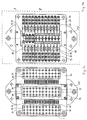
- the holes and thus the socket contact elements are each in three groups 37, 38, 39 arranged starting from the recesses 33, 34, 35 and arranged according to a square grid of 3 x 12 units.
- Form recesses 40, 41, 42 are each assigned to a field of 3 x 3 through holes in groups of three within the recesses. Between the recesses 41, 42, the corresponding edge of the first recesses 33, 34 has an undercut 43.
- the element 22 has recesses 51, 53 on the upper side with conductor rails 52, 54 inserted therein.
- the connector 11 has a central opening 55 approximately in overlap with the recess 35 in the element 21.
- Two rows of counterbores 56 for bridging contact elements are aligned with the corresponding openings 36 in the first element 21.
- the supplementary element 23, 24, 25 is inserted into the opening 55 of the element 22.
- the elements 21, 22 can preferably be screwed or glued to one another. The details described so far form the connector 11 according to the invention.
- the conductor rails 52, 54 are cranked and connected to the contact sockets 13, 14 of the first two groups 37, 38 of the bores.
- a conductor rail 57 is connected directly to the contact sockets 15 of the third group 39 of the bores.
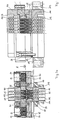
- a supplementary element 23 is inserted into the recess 55 and has a group of bores 45 with socket contact inserts 16 in the same arrangement as the group of bores 39 in the element 22.
- the respective outer of the socket contact elements 16 are conductively connected to the conductor rails 52, 54.
- the middle of the socket contact elements 16 are conductively connected to the conductor rails 57.
- the socket contact elements 16 of the supplementary part 23 are connected in a plug connection to an adapter plug 111 which has continuous pin contact elements 112.
- the middle of these pin contact elements 112 are cranked in order to create a transition from the contact image according to FIG. 1c to a contact image according to FIG. 1e.
- the latter contact picture of a 35-pin connector corresponds to an operating standard of the applicant HTS-Elektrotechnik GmbH.
- the adapter plug 111 is inserted into an attachment housing 113 which is fastened to a control cabinet wall 121.
- the connector 11 is fixed at a corresponding distance from the housing wall 121 by means of spacers 122, so that a secure plug connection is produced while the parts 23, 111 are in direct contact.
- the elements 21, 22 are connected to one another by means of screws 26, while the supplementary element 23 is fastened to the element 22 by means of screws 27.
- the plug connector 11 as a whole is fastened to the control cabinet wall 121 by means of screws 28.
- the cranked pin contact elements 112 of the middle row, offset by half a hole spacing, are visible in detail.
- a bore 39 in element 22 can remain unoccupied.
- the two rows of recesses 36 for the bridge contact elements can be seen in FIG. 1c; their continuation through the countersinks 56 is visible in FIG. 1d.
- the offset cutting planes A, B are indicated here.
- the conductor rails 52, 53 each connect four socket contact elements and the conductor rails 57 each connect three Contact elements.
- the respective last conductor rails 52, 54 can be unbalanced due to the absence of a conductor rail 57 there.
- the conductor rails each show lateral outbreaks 58 into which the contact bridge elements 91 are inserted and which in cross section make the conductor rails appear to be interrupted, which, however, as shown here, does not apply.
- the adapter contact insert 111 can be seen in its special shape and the add-on housing 113 with the known details.
- the underside of the connector 11 can be seen, since the control cabinet wall is not shown in FIGS. 1c to 1e.
- plug frames 61 of a first type which are oriented in mirror image, are inserted into the recesses 33, 34 and are described in more detail below with reference to FIGS.
- the plug-in frames 61 have latching lugs which engage in the undercut 43 of the recesses 33, 34.
- a holding frame insert 71 is inserted into the recess 35 and in turn has a recess 72 which corresponds to the recesses 33, 34. This also has an undercut 73 in the manner of the undercut 43.
- a plug frame 61 of a second type is also inserted into the recess 72.
- These plug frames 61 also have latching lugs which engage in the undercut 73.
- the plug frame 61 are designed to accommodate three-pin plugs, which will be discussed again in connection with FIG. 5.
- a first three-pin plug 81 is shown centrally in FIG. 1a in a longitudinal section through its three pin contact elements 82. Three such three-pin plugs 81 are shown in FIG a pin contact element 82 is shown. Cables 83 are crimped onto the contact elements 82. The pin contact elements 82 are each positively locked in through openings 84 in the three-pin plugs 81.
- FIGS. 2a-e the same parts as in FIGS. 1a-e are provided with the same reference numbers. To this extent, reference is made to the description.
- a differently designed supplementary element 24 is provided, which has a recess 46 on the outside with an undercut 47 for receiving further connector frames 61.
- stepped parallel through holes 48 there are further socket elements 16 in the supplementary element 24.
- the conductor rails 52, 54 in the element 27 are extended in such a way that they are additionally conductively connected to the respective outer sockets in the middle group of sockets 15.
- the middle bushing of this middle group of bushings 15 extends in one piece with the middle bushing 16 continuously from the second element 22 to the supplementary element 24.
- a middle conductor rail is omitted.
- 2e shows the different image of the supplementary element 24 with the recess 46 and the bores 48, which corresponds to the recesses 33, 34 and 71.
- FIGS. 3a-e the same parts as in FIGS. 1a-e are provided with the same reference numbers. To this extent, reference is made to the description.
- a second adapter contact insert 141 with all features of the type 111 already mentioned in FIG. 1 is inserted into the central recess 35.
- the adapter contact insert 141 has fastening flanges 142.
- the supplementary element 23, as described in FIG. 1, is supplemented by such an adapter contact insert 111, which is inserted into an attachment housing 113 and has cranked pin contact elements 112.
- FIGS. 3c and 3e the contact images of a 35-pin connector with an offset middle row can be seen in FIGS. 3c and 3e in accordance with the operating standard of the applicant HTS-Elektrotechnik GmbH.
- FIGS. 4a-e the same parts as in FIGS. 2a-e are provided with the same reference numbers. To this extent, reference is made to the description.
- a cover element 25 is inserted into the recess 55 of the second element 22, so that there is no possibility of plug connection from the second side.
- conductor rails 52, 54 are used, which connect the contact sockets 13, 14 in the first and second groups of bores 37, 38 to the outer socket contact elements 15 in the middle bores 39, respectively.
- middle conductor rails 59 of a second type are provided, each of which connects three socket contacts 15 one behind the other in the direction of the recesses.
- a connector 151 can be seen, which corresponds in its outer shape to the connector frame 61, but which only receives a central, in particular reinforced pin contact insert 157 and forms a ground connection.
- this is connected via a contact rail 158 to 18 socket contact elements 13, 14 of the bore groups 37, 38. It can also be seen in FIG. 4d that instead of the third conductor rail 59, extended conductor rails 159, 160 can also be used to connect five contact elements each.
- FIG. 5 shows a three-pin plug 81 with the details already described with reference to FIG. 1a.
- the plug comprises an upper, wider grip and stop part 85 and an insertion section 86 of reduced cross-section.
- the insertion section 86 is delimited at one end by an arch wall 87 and at the other end by a straight wall 88.
- a plug-in connection is therefore only possible in a certain orientation. If the three-pin connector is always assigned according to the same scheme, for example two signal lines to the round end, one ground line to the blunt end, incorrect connections can be excluded.
- a plug-in frame 61a is shown in a first embodiment in FIG. This can be seen from the latch 62 already mentioned, which is resilient due to the small wall thickness. There are still nine bottom holes 63 visible in a square grid, as well as molded projections 64, 65, 66, which complement each other with the recesses 40, 41, 42 in the recesses 37, 38, 71, 46 so that only one assembly with a clear orientation and is possible in predetermined positions. Three recesses 67 for receiving a previously described three-pole plug, which are separated by intermediate walls 68, run parallel to the outer walls without molded projections.
- FIG. 7 shows a connector frame 61b of a second type, on which the details already described in FIG. 6 are denoted by the same numbers and can also be recognized.
- the partition walls 68 that lie between the openings 67 are visible.
- the Openings 67 are arranged parallel to the walls with the molded projections 64, 65, 66, that is to say perpendicular to the aforementioned slots according to FIG. 6.
- a connector housing 161 is shown with nine through holes 163 arranged in square grids, which has the same outer shape as the plug frame 61, i. H. that is, shaped projections 164, 165, 166 arranged on opposite sides and a locking lug 162.
- FIG. 9 shows the connector 151 according to FIG. 4b in a position rotated through 90 ° in vertical section and in plan view, the locking lug 152, the outer molded projections 154, 155, 156 and the pin contact 157 inserted into the through opening 153 being recognizable.
- a bridge contact pin 91 can be seen in FIG. 10 in a view and in a section, which consists of an essentially U-shaped conductor bracket 92 and an insulating handle 93.
- the legs of the U-shaped bracket 92 are longitudinally slotted and notched on the outside, so that they can snap into place laterally at the level of the conductor rail.
- connectors with a larger number of contacts for example with 46 contacts, can also be designed using the same principle.
Landscapes
- Connector Housings Or Holding Contact Members (AREA)
- Connections Arranged To Contact A Plurality Of Conductors (AREA)
- Piezo-Electric Or Mechanical Vibrators, Or Delay Or Filter Circuits (AREA)
- Quick-Acting Or Multi-Walled Pipe Joints (AREA)
- Earth Drilling (AREA)
- Cable Accessories (AREA)
- Mechanical Coupling Of Light Guides (AREA)
- Coupling Device And Connection With Printed Circuit (AREA)
Applications Claiming Priority (2)
| Application Number | Priority Date | Filing Date | Title |
|---|---|---|---|
| DE19513880A DE19513880C2 (de) | 1995-04-18 | 1995-04-18 | Steckverbinder |
| DE19513880 | 1995-04-18 |
Publications (3)
| Publication Number | Publication Date |
|---|---|
| EP0739060A2 true EP0739060A2 (fr) | 1996-10-23 |
| EP0739060A3 EP0739060A3 (fr) | 1997-07-23 |
| EP0739060B1 EP0739060B1 (fr) | 2002-01-30 |
Family
ID=7759555
Family Applications (1)
| Application Number | Title | Priority Date | Filing Date |
|---|---|---|---|
| EP95112731A Expired - Lifetime EP0739060B1 (fr) | 1995-04-18 | 1995-08-12 | Connecteur à broche |
Country Status (3)
| Country | Link |
|---|---|
| EP (1) | EP0739060B1 (fr) |
| AT (1) | ATE212757T1 (fr) |
| DE (2) | DE19513880C2 (fr) |
Cited By (6)
| Publication number | Priority date | Publication date | Assignee | Title |
|---|---|---|---|---|
| WO1998045908A3 (fr) * | 1997-04-09 | 1998-12-30 | Siemens Ag | Distributeur electrique a conducteur commun |
| FR2783103A1 (fr) * | 1998-09-03 | 2000-03-10 | Positronic Ind | Dispositif d'adaptation de connecteurs entre eux |
| EP1337011A1 (fr) * | 2002-02-18 | 2003-08-20 | Lewden Electrical Industries | Répartiteur |
| WO2006006944A1 (fr) * | 2004-07-15 | 2006-01-19 | Elimsan Salt Cihazlari Ve Elektromekanik | Composant de connexion a barre pour prise |
| WO2011101318A1 (fr) * | 2010-02-22 | 2011-08-25 | Tyco Electronics Amp Italia Srl | Unité connecteur répartiteur pour installations électriques |
| DE202018002278U1 (de) | 2018-05-08 | 2019-08-13 | WAGO Verwaltungsgesellschaft mit beschränkter Haftung | Stiftleiste zur Anordnung in einer Wandöffnung |
Families Citing this family (5)
| Publication number | Priority date | Publication date | Assignee | Title |
|---|---|---|---|---|
| DE20003225U1 (de) * | 2000-02-23 | 2001-07-05 | Weidmüller Interface GmbH & Co, 32760 Detmold | Steckverbinder für elektrische Steuerungen und dessen Verwendung |
| DE10013346C2 (de) * | 2000-03-17 | 2002-01-17 | Wieland Electric Gmbh | Durchführungsadapter und Steckverbinder für einen Durchführungsadapter |
| DE102004030698A1 (de) * | 2004-06-24 | 2006-01-19 | Behr Gmbh & Co. Kg | Vorrichtung zum Anschluss einer elektrischen Basiskomponente und einer elektrischen Zusatzkomponente an ein Leitungsnetz, insbesondere eines Kraftfahrzeugs, und Verfahren zur Herstellung einer derartigen Anschlussvorrichtung |
| DE102008023979B4 (de) * | 2008-05-16 | 2010-05-12 | Wago Verwaltungsgesellschaft Mbh | Anschlussadapter |
| DE102018111734B3 (de) * | 2018-05-16 | 2019-06-06 | Harting Electric Gmbh & Co. Kg | Hochstromsteckverbinder und Verfahren zu seiner Montage |
Citations (1)
| Publication number | Priority date | Publication date | Assignee | Title |
|---|---|---|---|---|
| DE9302091U1 (de) | 1993-02-13 | 1993-04-22 | HTS-Elektrotechnik GmbH, 5206 Neunkirchen-Seelscheid | Vielpoliger Steckereinsatz |
Family Cites Families (9)
| Publication number | Priority date | Publication date | Assignee | Title |
|---|---|---|---|---|
| US3140139A (en) * | 1961-11-02 | 1964-07-07 | Grayhill Moldtronics Inc | Connector assembly |
| US3263203A (en) * | 1963-05-22 | 1966-07-26 | Emtec Inc | One-piece dual-barrel electrical connector |
| US3349363A (en) * | 1965-12-10 | 1967-10-24 | Ronald D Goodman | Electrical plug unit embodying duplex outlets |
| US4618196A (en) * | 1985-05-30 | 1986-10-21 | Itt Corporation | Gender reversal connector |
| US4806110A (en) * | 1986-06-19 | 1989-02-21 | Labinal Components And Systems, Inc. | Electrical connectors |
| DE4022000A1 (de) * | 1990-07-11 | 1992-01-16 | Rosemount Gmbh & Co | Verzweigungsstecker zum verbinden elektronischer geraete |
| EP0608221B1 (fr) * | 1991-10-17 | 1996-12-11 | Itt Industries, Inc. | Dispositif d'interconnexion |
| US5259776A (en) * | 1992-01-31 | 1993-11-09 | Augat Inc. | Fully programmable DIN connector |
| DE9217560U1 (de) * | 1992-12-22 | 1993-02-18 | Ju, Ted, Taipei, Hsien | Elektrischer Stecker |
-
1995
- 1995-04-18 DE DE19513880A patent/DE19513880C2/de not_active Expired - Fee Related
- 1995-08-12 AT AT95112731T patent/ATE212757T1/de not_active IP Right Cessation
- 1995-08-12 DE DE59510027T patent/DE59510027D1/de not_active Expired - Fee Related
- 1995-08-12 EP EP95112731A patent/EP0739060B1/fr not_active Expired - Lifetime
Patent Citations (1)
| Publication number | Priority date | Publication date | Assignee | Title |
|---|---|---|---|---|
| DE9302091U1 (de) | 1993-02-13 | 1993-04-22 | HTS-Elektrotechnik GmbH, 5206 Neunkirchen-Seelscheid | Vielpoliger Steckereinsatz |
Cited By (10)
| Publication number | Priority date | Publication date | Assignee | Title |
|---|---|---|---|---|
| WO1998045908A3 (fr) * | 1997-04-09 | 1998-12-30 | Siemens Ag | Distributeur electrique a conducteur commun |
| FR2783103A1 (fr) * | 1998-09-03 | 2000-03-10 | Positronic Ind | Dispositif d'adaptation de connecteurs entre eux |
| EP1337011A1 (fr) * | 2002-02-18 | 2003-08-20 | Lewden Electrical Industries | Répartiteur |
| WO2006006944A1 (fr) * | 2004-07-15 | 2006-01-19 | Elimsan Salt Cihazlari Ve Elektromekanik | Composant de connexion a barre pour prise |
| WO2011101318A1 (fr) * | 2010-02-22 | 2011-08-25 | Tyco Electronics Amp Italia Srl | Unité connecteur répartiteur pour installations électriques |
| CN102771016A (zh) * | 2010-02-22 | 2012-11-07 | 泰科电子(Amp)意大利公司 | 用于电气设备的分支器连接器单元 |
| US8708735B2 (en) | 2010-02-22 | 2014-04-29 | Tyco Electronics Amp Italia Srl | Splitter connector unit for electrical installations |
| CN102771016B (zh) * | 2010-02-22 | 2016-01-20 | 泰科电子(Amp)意大利公司 | 用于电气设备的分支器连接器单元 |
| AU2011217375B2 (en) * | 2010-02-22 | 2016-06-09 | Tyco Electronics Amp Italia Srl | A splitter connector unit for electrical installations |
| DE202018002278U1 (de) | 2018-05-08 | 2019-08-13 | WAGO Verwaltungsgesellschaft mit beschränkter Haftung | Stiftleiste zur Anordnung in einer Wandöffnung |
Also Published As
| Publication number | Publication date |
|---|---|
| EP0739060A3 (fr) | 1997-07-23 |
| DE59510027D1 (de) | 2002-03-14 |
| DE19513880A1 (de) | 1996-10-24 |
| DE19513880C2 (de) | 1998-07-09 |
| EP0739060B1 (fr) | 2002-01-30 |
| ATE212757T1 (de) | 2002-02-15 |
Similar Documents
| Publication | Publication Date | Title |
|---|---|---|
| DE69219791T2 (de) | Modulare auswechselbare Energieverteilungsvorrichtung | |
| EP0123822B1 (fr) | Connecteur transversal pour bornes alignées | |
| DE3917697C2 (fr) | ||
| EP1022934B1 (fr) | Tronçon de bus pour appareil électrique | |
| DE19902745B4 (de) | Elektrisches Gerät | |
| DE19964156A1 (de) | Elektrisches Gerät | |
| EP3281254B1 (fr) | Système de rangement en nid d'abeille | |
| EP0739060B1 (fr) | Connecteur à broche | |
| EP0636281B1 (fr) | Bloc de contact pour connecteurs multipolaires | |
| DE29505272U1 (de) | Sensor-Aktor-Verteiler | |
| DE3879365T2 (de) | Klinkensteckermodul mit eingebauten lampen. | |
| EP0097255A1 (fr) | Connecteur distributeur | |
| DE3880069T2 (de) | Klinkenfeld mit geteilter Frontplatte. | |
| EP0762583A2 (fr) | Système de barres omnibus à basse tension | |
| DE2714158C3 (de) | Anschlußvorrichtung für ein vieladriges Rundkabel | |
| DE3641153C2 (fr) | ||
| DE10204934A1 (de) | Anschluß- oder Verteilvorrichtung für elektrische Installationsgeräte | |
| EP3923417B1 (fr) | Boîte de dérivation | |
| DE2712723A1 (de) | Elektrischer verteiler | |
| DE20301077U1 (de) | Anschluß- und/oder Verbindungsklemme | |
| DE2116342A1 (de) | Elektrische Steckverbinder | |
| DE10157099B4 (de) | Elektrischer Verbinder für die Datentechnik | |
| EP0746064B1 (fr) | Plaque à bornes pour des plaquettes de circuits | |
| DE2507904A1 (de) | Anschlussverteiler | |
| EP0709918A1 (fr) | Bloc de connexion multipolaire à double rangée |
Legal Events
| Date | Code | Title | Description |
|---|---|---|---|
| PUAI | Public reference made under article 153(3) epc to a published international application that has entered the european phase |
Free format text: ORIGINAL CODE: 0009012 |
|
| AK | Designated contracting states |
Kind code of ref document: A2 Designated state(s): AT CH DE ES FR GB IT LI NL SE |
|
| PUAL | Search report despatched |
Free format text: ORIGINAL CODE: 0009013 |
|
| AK | Designated contracting states |
Kind code of ref document: A3 Designated state(s): AT CH DE ES FR GB IT LI NL SE |
|
| 17P | Request for examination filed |
Effective date: 19971209 |
|
| RAP1 | Party data changed (applicant data changed or rights of an application transferred) |
Owner name: THE WHITAKER CORPORATION |
|
| 17Q | First examination report despatched |
Effective date: 19990628 |
|
| GRAG | Despatch of communication of intention to grant |
Free format text: ORIGINAL CODE: EPIDOS AGRA |
|
| GRAG | Despatch of communication of intention to grant |
Free format text: ORIGINAL CODE: EPIDOS AGRA |
|
| GRAH | Despatch of communication of intention to grant a patent |
Free format text: ORIGINAL CODE: EPIDOS IGRA |
|
| GRAH | Despatch of communication of intention to grant a patent |
Free format text: ORIGINAL CODE: EPIDOS IGRA |
|
| GRAA | (expected) grant |
Free format text: ORIGINAL CODE: 0009210 |
|
| REG | Reference to a national code |
Ref country code: GB Ref legal event code: IF02 |
|
| RIC1 | Information provided on ipc code assigned before grant |
Free format text: 7H 01R 24/00 A, 7H 01R 31/06 B, 7H 01R 31/02 B |
|
| AK | Designated contracting states |
Kind code of ref document: B1 Designated state(s): AT CH DE ES FR GB IT LI NL SE |
|
| PG25 | Lapsed in a contracting state [announced via postgrant information from national office to epo] |
Ref country code: NL Free format text: LAPSE BECAUSE OF FAILURE TO SUBMIT A TRANSLATION OF THE DESCRIPTION OR TO PAY THE FEE WITHIN THE PRESCRIBED TIME-LIMIT Effective date: 20020130 |
|
| REF | Corresponds to: |
Ref document number: 212757 Country of ref document: AT Date of ref document: 20020215 Kind code of ref document: T |
|
| REG | Reference to a national code |
Ref country code: CH Ref legal event code: EP |
|
| REF | Corresponds to: |
Ref document number: 59510027 Country of ref document: DE Date of ref document: 20020314 |
|
| PG25 | Lapsed in a contracting state [announced via postgrant information from national office to epo] |
Ref country code: SE Free format text: LAPSE BECAUSE OF FAILURE TO SUBMIT A TRANSLATION OF THE DESCRIPTION OR TO PAY THE FEE WITHIN THE PRESCRIBED TIME-LIMIT Effective date: 20020430 |
|
| REG | Reference to a national code |
Ref country code: CH Ref legal event code: NV Representative=s name: PA ALDO ROEMPLER |
|
| GBT | Gb: translation of ep patent filed (gb section 77(6)(a)/1977) |
Effective date: 20020407 |
|
| NLV1 | Nl: lapsed or annulled due to failure to fulfill the requirements of art. 29p and 29m of the patents act | ||
| PG25 | Lapsed in a contracting state [announced via postgrant information from national office to epo] |
Ref country code: ES Free format text: LAPSE BECAUSE OF FAILURE TO SUBMIT A TRANSLATION OF THE DESCRIPTION OR TO PAY THE FEE WITHIN THE PRESCRIBED TIME-LIMIT Effective date: 20020730 |
|
| ET | Fr: translation filed | ||
| PG25 | Lapsed in a contracting state [announced via postgrant information from national office to epo] |
Ref country code: LI Free format text: LAPSE BECAUSE OF NON-PAYMENT OF DUE FEES Effective date: 20020831 Ref country code: CH Free format text: LAPSE BECAUSE OF NON-PAYMENT OF DUE FEES Effective date: 20020831 |
|
| PLBE | No opposition filed within time limit |
Free format text: ORIGINAL CODE: 0009261 |
|
| STAA | Information on the status of an ep patent application or granted ep patent |
Free format text: STATUS: NO OPPOSITION FILED WITHIN TIME LIMIT |
|
| 26N | No opposition filed | ||
| REG | Reference to a national code |
Ref country code: CH Ref legal event code: PL |
|
| PGFP | Annual fee paid to national office [announced via postgrant information from national office to epo] |
Ref country code: AT Payment date: 20050720 Year of fee payment: 11 |
|
| PGFP | Annual fee paid to national office [announced via postgrant information from national office to epo] |
Ref country code: GB Payment date: 20050804 Year of fee payment: 11 |
|
| PG25 | Lapsed in a contracting state [announced via postgrant information from national office to epo] |
Ref country code: IT Free format text: LAPSE BECAUSE OF NON-PAYMENT OF DUE FEES;WARNING: LAPSES OF ITALIAN PATENTS WITH EFFECTIVE DATE BEFORE 2007 MAY HAVE OCCURRED AT ANY TIME BEFORE 2007. THE CORRECT EFFECTIVE DATE MAY BE DIFFERENT FROM THE ONE RECORDED. Effective date: 20050812 |
|
| PGFP | Annual fee paid to national office [announced via postgrant information from national office to epo] |
Ref country code: FR Payment date: 20050817 Year of fee payment: 11 |
|
| PGFP | Annual fee paid to national office [announced via postgrant information from national office to epo] |
Ref country code: DE Payment date: 20050930 Year of fee payment: 11 |
|
| PG25 | Lapsed in a contracting state [announced via postgrant information from national office to epo] |
Ref country code: AT Free format text: LAPSE BECAUSE OF NON-PAYMENT OF DUE FEES Effective date: 20060812 |
|
| PG25 | Lapsed in a contracting state [announced via postgrant information from national office to epo] |
Ref country code: DE Free format text: LAPSE BECAUSE OF NON-PAYMENT OF DUE FEES Effective date: 20070301 |
|
| GBPC | Gb: european patent ceased through non-payment of renewal fee |
Effective date: 20060812 |
|
| REG | Reference to a national code |
Ref country code: FR Ref legal event code: ST Effective date: 20070430 |
|
| PG25 | Lapsed in a contracting state [announced via postgrant information from national office to epo] |
Ref country code: GB Free format text: LAPSE BECAUSE OF NON-PAYMENT OF DUE FEES Effective date: 20060812 |
|
| PG25 | Lapsed in a contracting state [announced via postgrant information from national office to epo] |
Ref country code: FR Free format text: LAPSE BECAUSE OF NON-PAYMENT OF DUE FEES Effective date: 20060831 |