EP0739647A1 - Evaporateur capillaire - Google Patents
Evaporateur capillaire Download PDFInfo
- Publication number
- EP0739647A1 EP0739647A1 EP96105520A EP96105520A EP0739647A1 EP 0739647 A1 EP0739647 A1 EP 0739647A1 EP 96105520 A EP96105520 A EP 96105520A EP 96105520 A EP96105520 A EP 96105520A EP 0739647 A1 EP0739647 A1 EP 0739647A1
- Authority
- EP
- European Patent Office
- Prior art keywords
- evaporator
- capillary
- capillary body
- liquid
- liq
- Prior art date
- Legal status (The legal status is an assumption and is not a legal conclusion. Google has not performed a legal analysis and makes no representation as to the accuracy of the status listed.)
- Withdrawn
Links
- 239000007788 liquid Substances 0.000 claims description 14
- 239000000463 material Substances 0.000 description 9
- 238000001704 evaporation Methods 0.000 description 4
- 230000008020 evaporation Effects 0.000 description 4
- 230000015572 biosynthetic process Effects 0.000 description 3
- 238000001035 drying Methods 0.000 description 3
- 239000007789 gas Substances 0.000 description 3
- 238000013461 design Methods 0.000 description 2
- 230000005484 gravity Effects 0.000 description 2
- 238000009736 wetting Methods 0.000 description 2
- 230000001133 acceleration Effects 0.000 description 1
- 238000009835 boiling Methods 0.000 description 1
- 238000001816 cooling Methods 0.000 description 1
- 238000011161 development Methods 0.000 description 1
- 230000000694 effects Effects 0.000 description 1
- 239000011261 inert gas Substances 0.000 description 1
- 239000012212 insulator Substances 0.000 description 1
- 238000000034 method Methods 0.000 description 1
- 239000000203 mixture Substances 0.000 description 1
- 230000010355 oscillation Effects 0.000 description 1
- 238000013021 overheating Methods 0.000 description 1
- 230000003071 parasitic effect Effects 0.000 description 1
- 238000000819 phase cycle Methods 0.000 description 1
- 238000005191 phase separation Methods 0.000 description 1
- 238000007493 shaping process Methods 0.000 description 1
- 238000012546 transfer Methods 0.000 description 1
Images

Classifications
-
- F—MECHANICAL ENGINEERING; LIGHTING; HEATING; WEAPONS; BLASTING
- F28—HEAT EXCHANGE IN GENERAL
- F28D—HEAT-EXCHANGE APPARATUS, NOT PROVIDED FOR IN ANOTHER SUBCLASS, IN WHICH THE HEAT-EXCHANGE MEDIA DO NOT COME INTO DIRECT CONTACT
- F28D15/00—Heat-exchange apparatus with the intermediate heat-transfer medium in closed tubes passing into or through the conduit walls ; Heat-exchange apparatus employing intermediate heat-transfer medium or bodies
- F28D15/02—Heat-exchange apparatus with the intermediate heat-transfer medium in closed tubes passing into or through the conduit walls ; Heat-exchange apparatus employing intermediate heat-transfer medium or bodies in which the medium condenses and evaporates, e.g. heat pipes
- F28D15/0266—Heat-exchange apparatus with the intermediate heat-transfer medium in closed tubes passing into or through the conduit walls ; Heat-exchange apparatus employing intermediate heat-transfer medium or bodies in which the medium condenses and evaporates, e.g. heat pipes with separate evaporating and condensing chambers connected by at least one conduit; Loop-type heat pipes; with multiple or common evaporating or condensing chambers
-
- B—PERFORMING OPERATIONS; TRANSPORTING
- B01—PHYSICAL OR CHEMICAL PROCESSES OR APPARATUS IN GENERAL
- B01D—SEPARATION
- B01D1/00—Evaporating
-
- F—MECHANICAL ENGINEERING; LIGHTING; HEATING; WEAPONS; BLASTING
- F28—HEAT EXCHANGE IN GENERAL
- F28F—DETAILS OF HEAT-EXCHANGE AND HEAT-TRANSFER APPARATUS, OF GENERAL APPLICATION
- F28F13/00—Arrangements for modifying heat-transfer, e.g. increasing, decreasing
- F28F13/18—Arrangements for modifying heat-transfer, e.g. increasing, decreasing by applying coatings, e.g. radiation-absorbing, radiation-reflecting; by surface treatment, e.g. polishing
- F28F13/185—Heat-exchange surfaces provided with microstructures or with porous coatings
- F28F13/187—Heat-exchange surfaces provided with microstructures or with porous coatings especially adapted for evaporator surfaces or condenser surfaces, e.g. with nucleation sites
Definitions
- the invention relates to an evaporator for two-phase circuits with an inlet for the liquid, an inlet for the heat flow, a steam outlet and a capillary body located in the evaporator housing.
- the delay in boiling combined with a blocked flow of steam from the capillary material can lead to pressure oscillations. Vapor bubbles are pressed through the capillary material to the liquid side, which can dry out the capillary material and cause the circuit to fail.
- the object of the invention is to provide an evaporator which makes it possible to work bubble-resistant at a low minimum heat load.
- Bubble-resistant means that the functionality of the circuit is guaranteed even if gas bubbles or steam bubbles occur in the evaporator. At the same time, the start-up behavior of the circuit is to be improved.
- Resistance to vapor bubble formation can be achieved by shaping the wall of the liquid reservoir in the evaporator with open grooves in accordance with the internal structure of a heat pipe. This creates an "open heat pipe" that connects to the actual capillary body stands and is always wetted with liquid. Design measures ensure that the grooves are always positively connected to the capillary material. Due to the capillary action in the grooves, the liquid-steam mixture is separated when steam bubbles occur and liquid is constantly supplied to the actual capillary body. By dimensioning the grooves, the capillary material can be supplied with liquid within limits, even against gravity. This ensures wetting of the capillary body with liquid in any case. Although gas bubbles and steam bubbles result in a loss of performance, the evaporation itself remains the driving motor of the cycle. In normal operation (bubble-free evaporator), the liquid transport mainly takes place outside the grooves of the "open heat pipe".
- the minimum heat load required for controlled evaporation largely depends on parasitic heat flows due to heat conduction through the capillary material itself and through the evaporator housing.
- the heat input into the liquid must be reduced.
- a plastic insert in the evaporator housing was previously proposed, which serves as a thermal insulator.
- this object is now to be provided with grooves and used as an "open heat pipe".
- the above-mentioned properties of the evaporator ensure permanent wetting of the capillary body even when it is at a standstill and a minimal heat load for starting the circuit.
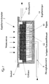
- the capillary evaporator 2 shown in FIG. 1 consists of the following components: housing 4 with cover 6 , liquid inlet 8 , plastic insert 12 provided with ribs 10 , capillary body 14 and steam outlet 16 .
- FIG. 2 and 3 show details of FIG. 1, the grooves 18 of the heat pipe structure in particular being recognizable.
- the dimensions and materials given are examples and can be adapted for individual applications.
Landscapes
- Engineering & Computer Science (AREA)
- Chemical & Material Sciences (AREA)
- Physics & Mathematics (AREA)
- Thermal Sciences (AREA)
- Mechanical Engineering (AREA)
- General Engineering & Computer Science (AREA)
- Chemical Kinetics & Catalysis (AREA)
- Life Sciences & Earth Sciences (AREA)
- Sustainable Development (AREA)
- Crystallography & Structural Chemistry (AREA)
- Drying Of Solid Materials (AREA)
- Cookers (AREA)
Applications Claiming Priority (2)
| Application Number | Priority Date | Filing Date | Title |
|---|---|---|---|
| DE1995115095 DE19515095A1 (de) | 1995-04-25 | 1995-04-25 | Kapillarverdampfer |
| DE19515095 | 1995-04-25 |
Publications (1)
| Publication Number | Publication Date |
|---|---|
| EP0739647A1 true EP0739647A1 (fr) | 1996-10-30 |
Family
ID=7760270
Family Applications (1)
| Application Number | Title | Priority Date | Filing Date |
|---|---|---|---|
| EP96105520A Withdrawn EP0739647A1 (fr) | 1995-04-25 | 1996-04-06 | Evaporateur capillaire |
Country Status (2)
| Country | Link |
|---|---|
| EP (1) | EP0739647A1 (fr) |
| DE (1) | DE19515095A1 (fr) |
Cited By (4)
| Publication number | Priority date | Publication date | Assignee | Title |
|---|---|---|---|---|
| EP1054583A3 (fr) * | 1999-05-20 | 2001-06-20 | TS Heatronics Co., Ltd. | Appareil pour refroidir des composants électroniques |
| WO2015014926A1 (fr) * | 2013-08-01 | 2015-02-05 | Euro Heat Pipes | Evaporateur à dispositif anti-retour pour boucle diphasique |
| CN105452795A (zh) * | 2013-08-01 | 2016-03-30 | 卡利奥斯公司 | 两相回路用具有简化装配的蒸发器 |
| CN114772901A (zh) * | 2022-05-31 | 2022-07-22 | 江苏省农业科学院 | 低能耗mvr干燥淤泥、污泥及脱氮除臭系统 |
Families Citing this family (1)
| Publication number | Priority date | Publication date | Assignee | Title |
|---|---|---|---|---|
| DE19752577A1 (de) * | 1997-11-27 | 1999-06-02 | Helmut Dipl Ing Wulf | Einrichtung zum Kühlen von Flüssigkeiten |
Citations (4)
| Publication number | Priority date | Publication date | Assignee | Title |
|---|---|---|---|---|
| DE3301998A1 (de) * | 1983-01-21 | 1984-07-26 | Otdel fiziko-techničeskich problem energetiki Ural'skogo naučnogo centra Akademii Nauk, Sverdlovsk | Waermeuebertragereinrichtung |
| US4520865A (en) * | 1984-06-25 | 1985-06-04 | Lockheed Missiles & Space Company, Inc. | Gas-tolerant arterial heat pipe |
| EP0210337A2 (fr) * | 1985-07-25 | 1987-02-04 | Dornier Gmbh | Evaporateur assisté par une structure capillaire |
| US4903761A (en) * | 1987-06-03 | 1990-02-27 | Lockheed Missiles & Space Company, Inc. | Wick assembly for self-regulated fluid management in a pumped two-phase heat transfer system |
-
1995
- 1995-04-25 DE DE1995115095 patent/DE19515095A1/de not_active Withdrawn
-
1996
- 1996-04-06 EP EP96105520A patent/EP0739647A1/fr not_active Withdrawn
Patent Citations (4)
| Publication number | Priority date | Publication date | Assignee | Title |
|---|---|---|---|---|
| DE3301998A1 (de) * | 1983-01-21 | 1984-07-26 | Otdel fiziko-techničeskich problem energetiki Ural'skogo naučnogo centra Akademii Nauk, Sverdlovsk | Waermeuebertragereinrichtung |
| US4520865A (en) * | 1984-06-25 | 1985-06-04 | Lockheed Missiles & Space Company, Inc. | Gas-tolerant arterial heat pipe |
| EP0210337A2 (fr) * | 1985-07-25 | 1987-02-04 | Dornier Gmbh | Evaporateur assisté par une structure capillaire |
| US4903761A (en) * | 1987-06-03 | 1990-02-27 | Lockheed Missiles & Space Company, Inc. | Wick assembly for self-regulated fluid management in a pumped two-phase heat transfer system |
Cited By (7)
| Publication number | Priority date | Publication date | Assignee | Title |
|---|---|---|---|---|
| EP1054583A3 (fr) * | 1999-05-20 | 2001-06-20 | TS Heatronics Co., Ltd. | Appareil pour refroidir des composants électroniques |
| US6360813B1 (en) | 1999-05-20 | 2002-03-26 | Ts Heatronics Co., Ltd. | Electronic components cooling apparatus |
| WO2015014926A1 (fr) * | 2013-08-01 | 2015-02-05 | Euro Heat Pipes | Evaporateur à dispositif anti-retour pour boucle diphasique |
| FR3009377A1 (fr) * | 2013-08-01 | 2015-02-06 | Euro Heat Pipes | Evaporateur a dispositif anti-retour pour boucle diphasique |
| CN105452795A (zh) * | 2013-08-01 | 2016-03-30 | 卡利奥斯公司 | 两相回路用具有简化装配的蒸发器 |
| US10036597B2 (en) | 2013-08-01 | 2018-07-31 | Calyos Sa | Evaporator with simplified assembly for diphasic loop |
| CN114772901A (zh) * | 2022-05-31 | 2022-07-22 | 江苏省农业科学院 | 低能耗mvr干燥淤泥、污泥及脱氮除臭系统 |
Also Published As
| Publication number | Publication date |
|---|---|
| DE19515095A1 (de) | 1996-10-31 |
Similar Documents
| Publication | Publication Date | Title |
|---|---|---|
| DE3220335C2 (de) | Wärmepumpensystem mit einer Kältemittelmischung | |
| DE3015525C2 (de) | Anlage zum Destillieren von Flüssigkeiten mit einer Wärmepumpe | |
| DE3422391C2 (de) | Zwischen Heiz- und Kühlbetrieb umschaltbare Kälteanlage | |
| DE3875006T2 (de) | Waermepumpensystem. | |
| DE3017236C2 (de) | Vorrichtung zum Erzeugen von Kälte | |
| DE69504357T2 (de) | Energieübertragungssystem zwischen einer wärmequelle und einer kältequelle | |
| DE2758773C2 (de) | Bivalente Heizanlage | |
| EP0021205B1 (fr) | Procédé de compression-absorption hybride pour pompes à chaleur ou machine frigorifique | |
| DE4222340A1 (de) | Wärmerohr | |
| EP0739647A1 (fr) | Evaporateur capillaire | |
| DE60211114T2 (de) | Speicher | |
| DE4125423A1 (de) | Waermetransportsystem | |
| DE2735593A1 (de) | Ventil fuer hochviskose medien fuehrende leitungen | |
| DE2261091A1 (de) | Anordnung zur oelkuehlung bei kuehlkompressoren des rotationstyps | |
| WO2001094862A1 (fr) | Groupe frigorifique | |
| EP0025986A1 (fr) | Procédé et dispositif pour l'utilisation de la chaleur recueillie à basse température | |
| DD256434A3 (de) | Waermeuebertrager fuer dynamische latentwaermespeicher | |
| DE1751717A1 (de) | Kuehlanlage,deren Verdampfer ueber ein regulierbares Expansionsventil gespeist wird | |
| DE69810901T2 (de) | Vorrichtung in einem schmierstoffkreislaufsystem | |
| DE3105796A1 (de) | "waermepumpe" | |
| EP0184181B1 (fr) | Pompe à chaleur | |
| DE3431452A1 (de) | Als waermepumpe genutztes kuehl- oder gefriergeraet | |
| DE102022201431A1 (de) | Sammler für einen Kältemittelkreislauf | |
| DE2945529A1 (de) | Warmwasserbereiter | |
| WO2001042723A1 (fr) | Dispositif refrigerant a absorption |
Legal Events
| Date | Code | Title | Description |
|---|---|---|---|
| PUAI | Public reference made under article 153(3) epc to a published international application that has entered the european phase |
Free format text: ORIGINAL CODE: 0009012 |
|
| AK | Designated contracting states |
Kind code of ref document: A1 Designated state(s): BE DE FR |
|
| 17P | Request for examination filed |
Effective date: 19961203 |
|
| 17Q | First examination report despatched |
Effective date: 19990421 |
|
| STAA | Information on the status of an ep patent application or granted ep patent |
Free format text: STATUS: THE APPLICATION IS DEEMED TO BE WITHDRAWN |
|
| 18D | Application deemed to be withdrawn |
Effective date: 19990903 |