EP0739656A2 - Ultraschallwandlerarray und Herstellungsverfahren - Google Patents
Ultraschallwandlerarray und Herstellungsverfahren Download PDFInfo
- Publication number
- EP0739656A2 EP0739656A2 EP96112139A EP96112139A EP0739656A2 EP 0739656 A2 EP0739656 A2 EP 0739656A2 EP 96112139 A EP96112139 A EP 96112139A EP 96112139 A EP96112139 A EP 96112139A EP 0739656 A2 EP0739656 A2 EP 0739656A2
- Authority
- EP
- European Patent Office
- Prior art keywords
- layer
- acoustic matching
- array
- piezoelectric substrate
- piezoelectric
- Prior art date
- Legal status (The legal status is an assumption and is not a legal conclusion. Google has not performed a legal analysis and makes no representation as to the accuracy of the status listed.)
- Granted
Links
Images


Classifications
-
- G—PHYSICS
- G10—MUSICAL INSTRUMENTS; ACOUSTICS
- G10K—SOUND-PRODUCING DEVICES; METHODS OR DEVICES FOR PROTECTING AGAINST, OR FOR DAMPING, NOISE OR OTHER ACOUSTIC WAVES IN GENERAL; ACOUSTICS NOT OTHERWISE PROVIDED FOR
- G10K11/00—Methods or devices for transmitting, conducting or directing sound in general; Methods or devices for protecting against, or for damping, noise or other acoustic waves in general
- G10K11/18—Methods or devices for transmitting, conducting or directing sound
- G10K11/26—Sound-focusing or directing, e.g. scanning
- G10K11/32—Sound-focusing or directing, e.g. scanning characterised by the shape of the source
-
- B—PERFORMING OPERATIONS; TRANSPORTING
- B06—GENERATING OR TRANSMITTING MECHANICAL VIBRATIONS IN GENERAL
- B06B—METHODS OR APPARATUS FOR GENERATING OR TRANSMITTING MECHANICAL VIBRATIONS OF INFRASONIC, SONIC, OR ULTRASONIC FREQUENCY, e.g. FOR PERFORMING MECHANICAL WORK IN GENERAL
- B06B1/00—Methods or apparatus for generating mechanical vibrations of infrasonic, sonic, or ultrasonic frequency
- B06B1/02—Methods or apparatus for generating mechanical vibrations of infrasonic, sonic, or ultrasonic frequency making use of electrical energy
- B06B1/06—Methods or apparatus for generating mechanical vibrations of infrasonic, sonic, or ultrasonic frequency making use of electrical energy operating with piezoelectric effect or with electrostriction
- B06B1/0607—Methods or apparatus for generating mechanical vibrations of infrasonic, sonic, or ultrasonic frequency making use of electrical energy operating with piezoelectric effect or with electrostriction using multiple elements
- B06B1/0622—Methods or apparatus for generating mechanical vibrations of infrasonic, sonic, or ultrasonic frequency making use of electrical energy operating with piezoelectric effect or with electrostriction using multiple elements on one surface
- B06B1/0633—Cylindrical array
-
- B—PERFORMING OPERATIONS; TRANSPORTING
- B06—GENERATING OR TRANSMITTING MECHANICAL VIBRATIONS IN GENERAL
- B06B—METHODS OR APPARATUS FOR GENERATING OR TRANSMITTING MECHANICAL VIBRATIONS OF INFRASONIC, SONIC, OR ULTRASONIC FREQUENCY, e.g. FOR PERFORMING MECHANICAL WORK IN GENERAL
- B06B1/00—Methods or apparatus for generating mechanical vibrations of infrasonic, sonic, or ultrasonic frequency
- B06B1/02—Methods or apparatus for generating mechanical vibrations of infrasonic, sonic, or ultrasonic frequency making use of electrical energy
- B06B1/06—Methods or apparatus for generating mechanical vibrations of infrasonic, sonic, or ultrasonic frequency making use of electrical energy operating with piezoelectric effect or with electrostriction
- B06B1/0688—Methods or apparatus for generating mechanical vibrations of infrasonic, sonic, or ultrasonic frequency making use of electrical energy operating with piezoelectric effect or with electrostriction with foil-type piezoelectric elements, e.g. PVDF
- B06B1/0692—Methods or apparatus for generating mechanical vibrations of infrasonic, sonic, or ultrasonic frequency making use of electrical energy operating with piezoelectric effect or with electrostriction with foil-type piezoelectric elements, e.g. PVDF with a continuous electrode on one side and a plurality of electrodes on the other side
-
- B—PERFORMING OPERATIONS; TRANSPORTING
- B06—GENERATING OR TRANSMITTING MECHANICAL VIBRATIONS IN GENERAL
- B06B—METHODS OR APPARATUS FOR GENERATING OR TRANSMITTING MECHANICAL VIBRATIONS OF INFRASONIC, SONIC, OR ULTRASONIC FREQUENCY, e.g. FOR PERFORMING MECHANICAL WORK IN GENERAL
- B06B2201/00—Indexing scheme associated with B06B1/0207 for details covered by B06B1/0207 but not provided for in any of its subgroups
- B06B2201/20—Application to multi-element transducer
-
- B—PERFORMING OPERATIONS; TRANSPORTING
- B06—GENERATING OR TRANSMITTING MECHANICAL VIBRATIONS IN GENERAL
- B06B—METHODS OR APPARATUS FOR GENERATING OR TRANSMITTING MECHANICAL VIBRATIONS OF INFRASONIC, SONIC, OR ULTRASONIC FREQUENCY, e.g. FOR PERFORMING MECHANICAL WORK IN GENERAL
- B06B2201/00—Indexing scheme associated with B06B1/0207 for details covered by B06B1/0207 but not provided for in any of its subgroups
- B06B2201/50—Application to a particular transducer type
- B06B2201/55—Piezoelectric transducer
- B06B2201/56—Foil type, e.g. PVDF
-
- Y—GENERAL TAGGING OF NEW TECHNOLOGICAL DEVELOPMENTS; GENERAL TAGGING OF CROSS-SECTIONAL TECHNOLOGIES SPANNING OVER SEVERAL SECTIONS OF THE IPC; TECHNICAL SUBJECTS COVERED BY FORMER USPC CROSS-REFERENCE ART COLLECTIONS [XRACs] AND DIGESTS
- Y10—TECHNICAL SUBJECTS COVERED BY FORMER USPC
- Y10T—TECHNICAL SUBJECTS COVERED BY FORMER US CLASSIFICATION
- Y10T29/00—Metal working
- Y10T29/42—Piezoelectric device making
Definitions
- This invention relates generally to ultrasonic transducer arrays and, more particularly, to an array having a plurality of individual, acoustically isolated elements that are uniformly distributed along an axis which is straight, curvilinear, or both.
- Ultrasonic transducer arrays are well-known in the art and have many applications, including diagnostic medical imaging, fluid flow sensing and the non-destructive testing of materials. Such applications typically require high sensitivity and broad band frequency response for optimum resolving power.
- An ultrasonic transducer array typically includes a plurality of individual transducer elements that are uniformly spaced along an array axis that is straight (i.e., a linear array), or curvilinear (e.g., a concave or convex array).
- the transducer elements each include a piezoelectric layer.
- the transducer elements also include one or more overlaying acoustic matching layers, typically each one-quarter wavelength thick.
- the array is electrically driven by variation of the transmit timing between adjacent transducer elements to produce a focused sound beam in an imaging plane.
- Increased transducer performance is achieved by electrically matching the individual transducer elements to a pulser/receiver circuit, by acoustically matching the individual transducer elements to the body to be tested, and by acoustically isolating the individual elements from each other.
- the acoustic matching layers are commonly employed to improve the transfer of sound energy from the piezoelectric elements into the body to be tested.
- One known transducer array that incorporates mechanical focusing is made with a plano-concave piezoelectric substrate.
- the cavity formed by the concave surface is filled with a polymer mixture, such as a tungsten-epoxy mixture, and then ground flat.
- An epoxy layer substrate or suitable quarter wave matching layer substrate is then affixed to the flat surface of the filler layer to improve transfer of acoustic energy from the device.
- Individual transducer elements are formed by cutting the resulting sandwiched substrates with a dicing saw. In the cutting process, the quarter wave matching layer substrate is uncut or only partially cut through so as to leave the individual transducer elements connected. The result of this construction is to provide an array that is mechanically focused while having a flat surface as its front face.
- a backing layer is affixed to support the transducer elements and to absorb or reflect acoustic energy transmitted from the piezoelectric substrate.
- this array provides an undesirable narrow band frequency response and low sensitivity.
- the non-uniform thickness of the filler layer inhibits the transfer of acoustic energy over a broad frequency range from the piezoelectric material into the body being scanned.
- narrow band frequency response increases the pulse length of the transmitted acoustic wave and thus limits the array's axial resolution.
- the contiguous acoustic matching layer gives rise to undesirable interelement crosstalk.
- the flexible backing plate is then formed along an axis that is straight, concave, or convex and bonded to a backing base.
- a silicone elastomer lens is affixed to the front surface of the quarter wave matching layers to effect the desired mechanical focusing of the individual elements.
- a further construction technique uses a concave arrangement of piezoelectric elements that are affixed along their front surfaces to a continuous, deformable, acoustic transition blade.
- the blade includes a metallization layer to electrically connect the front surfaces of the piezoelectric elements.
- the rear surfaces of the piezoelectric elements are individually connected to separate lead wires.
- a disadvantage of this construction is that the blade metallization and the blade itself are continuous across the piezoelectric elements, adversely affecting the transducer performance. Additionally, the individual attachment of lead wires to the piezoelectric elements is time consuming and possibly damaging to the material.
- each element has a piezoelectric layer that is mechanically focused without the necessity of an acoustic lens and that is affixed to one or more uniform thickness, similarly focused, quarter wave matching layers.
- the individual transducer elements including the respective piezoelectric and matching layers, should also be mechanically isolated from each other along the array axis to form independent transducer elements that are formable along a linear or curvilinear path.
- the present invention satisfies this need.
- the ultrasonic transducer array of the present invention may be in the form of a probe for use with ultrasound apparatus.
- the array includes a plurality of individual transducer elements with each transducer element possessing a piezoelectric layer having a concave front surface and a rear surface and an acoustic matching layer having a concave front surface, a rear surface and uniform thickness.
- concave is meant to include indentations that are formed of curved segments or straight segments or a combination thereof.
- the rear surface of the acoustic matching layer is mounted to the concave front surface of the piezoelectric layer.
- the shapes of the front surface of the piezoelectric layer and the front and rear surfaces of the acoustic matching layer are suitable to mechanically focus the respective transducer element into an imaging plane.
- the array further includes a backing support that supports the transducer elements in a spaced apart relationship and aligns the transducer elements along an array axis located in the imaging plane.
- the front surface of the piezoelectric layer may include a series of slots arranged in the direction of the array axis.
- the slots serve the purpose of minimizing lateral resonance modes and reducing the bulk acoustic impedance of the piezoelectric layer.
- the slots permit the piezoelectric layer to be readily formed into a concave shape.
- a piezoelectric substrate (that will eventually be mounted to an acoustic matching layer substrate and cut to form the individual transducer elements) is metallized and a rear surface thereof provided with isolation cuts to form a wrap-around front surface electrode and an isolated rear surface electrode.
- a flexible printed circuit board having electrode lead patterns may be soldered to the isolated rear surface electrode.
- Ground foils may be soldered to the wrap-around front surface electrode. Cutting the piezoelectric substrate at this time will then result in each transducer element having its own electrode lead and ground connection.
- a layer of suitably conductive material such as copper, may be interposed between the piezoelectric substrate and the acoustic matching layer substrate to ensure electrical connection across the slots to the ground connection.
- Another feature of the invention is that the individual transducer elements themselves may be subdivided while maintaining the electrical interconnection thereto. Such a structure further reduces spurious lateral resonance modes and inter-element crosstalk.
- the improved method of making the ultrasonic transducer array described above includes the steps of providing a piezoelectric substrate having a front concave surface and a rear surface and applying one or more acoustic matching layers of substantially uniform thickness to the concave front surface of the piezoelectric substrate to produce an intermediate assembly.
- the intermediate assembly is affixed to a flexible front carrier plate and a series of substantially parallel cuts are made completely through the intermediate assembly and into the flexible front carrier plate.
- the cuts form a series of individual transducer elements aligned along an array axis, each having a piezoelectric layer and an acoustic matching layer or layers.
- the parallel cut intermediate assembly is formed into a desired shape by bending the layers against the yielding bias of the flexible front carrier plate about an array axis in the imaging plane.
- the formed intermediate assembly is then affixed to a backing support adjacent the rear surface of the piezoelectric substrate and the temporary front carrier plate is removed yielding the ultrasonic transducer array.
- An added beneficial step to the above described method is to make a series of parallel cuts substantially through the piezoelectric substrate to form the aforementioned slots in the concave front surface of the piezoelectric substrate.
- Yet another beneficial step is the use of a thermoplastic adhesive between the flexible front carrier plate and the acoustic matching layer(s), wherein the thermoplastic adhesive loses its adhesion above a predetermined temperature and releases the carrier plate.
- the above method may be further improved by filling the cuts and slots with a low impedance acoustically attenuative material to further improve the resonance quality of the array. Further benefits may be obtained by affixing an elastomeric filler layer to the exposed concave surface of the acoustic matching layer(s) after the flexible front carrier plate has been removed, and thus electrically insulate the individual transducer elements and improve acoustic coupling.
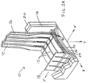
- FIG. 1 is an isometric view, partly in section, of a preferred embodiment of an ultrasonic transducer array made according to the present invention. A portion of the array has been set out from the remainder for illustrative purposes.
- FIG. 2A is an enlarged sectional view of the set out portion of the array in FIG. 1 showing the transducer elements in detail.
- FIG. 2B is a modified form of the portion of the array in FIG. 2A showing transducer subelements.
- FIG. 3 is a cross-sectional end view of the piezoelectric substrate of the present invention.
- FIG. 4 is a cross-sectional end view of the piezoelectric substrate of FIG. 3 having a series of saw cuts.
- FIG. 5 is a cross-sectional end view of the acoustic matching layer(s) substrate of the present invention.
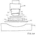
- FIGS. 6A and 6B are end views showing the pressing operations of the present invention.
- FIG. 7 is a cross-sectional end view of the piezoelectric and acoustic matching layer substrates mounted to the flexible front carrier plate according to the present invention.
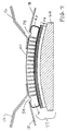
- FIG. 8 is a cross-sectional front view of the front carrier plate and corresponding transducer elements with flexible printed circuit leads, mounted to a convex form tool according to the present invention.
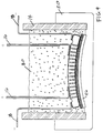
- FIG. 9 is a cross-sectional end view of a transducer element and corresponding lead attachments encapsulated by a dielectric face layer and a backing material according to the present invention.
- FIG. 1 An ultrasonic transducer array 10 made according to the present invention is shown in FIG. 1.
- the array includes a plurality of individual ultrasonic transducer elements 12 encased within a housing 14.
- the individual elements are electrically connected to the leads 16 of a flexible printed circuit board and ground foils 18 that are fixed in position by a polymer backing material 80.
- a dielectric face layer 20 is formed around the array and the housing.
- Each individual ultrasonic transducer element 12 is made up of a piezoelectric layer 22, a first acoustic matching layer 24 and a second acoustic matching layer 26 (see also FIG. 2A).
- the individual elements are mechanically focused into a desired imaging plane (defined by the x-y axes) due to the concave shape of the piezoelectric and adjoining acoustic matching layers.
- the individual elements are also mechanically isolated from each other along an array axis A located in the imaging plane (as may be defined by the midpoints of the chords extending between the ends of each transducer element).
- Front surfaces of the piezoelectric layer 22 and acoustic matching layers 24, 26 are concave in the direction of an axis B perpendicular to the array axis A.
- the array axis A has a convex shape to enable sector scanning. It will become apparent from the following, however, that the array axis may be straight or curvilinear or may even have a combination of straight parts and curved parts.
- the array of individual ultrasonic transducer elements may be made in the following preferred manner.
- a piece of piezoelectric ceramic material is ground flat and cut to a rectangular shape to form a substrate 30 having a front surface 32 and a rear surface 34.
- a particularly suitable piezoelectric ceramic material is one made by Motorola Ceramic Products, type 3203HD. This material had high density and strength which facilitate the cutting steps to be made without fracture of the individual elements.
- the piezoelectric substrate 30 is further prepared by applying a metallization layer 36 such as by first etching the surfaces with a 5% fluoboric acid solution and then electroless nickel plating using commonly available commercial plating materials and means. Other methods may be substituted for plating the piezoelectric such as vacuum deposition of chromium, nickel, gold, or other metals.
- the plating material is made to extend completely around all the surfaces of the piezoelectric substrate.
- a subsequent copper layer (approximately 2 micron thickness) is electroplated onto the first nickel layer (approximately 1 micron thickness) followed by a thin layer of electroplated gold ( ⁇ 0.1 micron thickness) to protect against corrosion.
- the metallization layer 36 is isolated to form two electrodes by making two saw cuts 38 through the rear surface 34 of the piezoelectric substrate.
- a wafer dicing saw may be used for this purpose.
- the two saw cuts form a rear surface electrode 40 and a separate front surface electrode 42.
- the front surface electrode includes wrap-around ends 44 that extend from the front surface 32 around to the rear surface 34 of the piezoelectric substrate.
- the wrap-around ends 44 preferably extend approximately 1 mm along each side of the rear surface.
- the metallized and isolated piezoelectric substrate 30 is prepared for cutting by turning it over and mounting the rear surface electrode 34 to a carrier film 46, such as an insulating polyester film.
- a thermoplastic adhesive may be used to affix the piezoelectric substrate to the carrier film.
- a wafer dicing saw a series of saw cuts 48 are made substantially through the piezoelectric substrate 30 preferably leaving only a small amount, for example 50 microns, of substrate material uncut between an inner end 49 of the saw cuts and the rear surface 34 of the substrate.
- the saw cuts may be made through the substrate 30, including into, but not all the way through, the rear surface electrode.
- the substrate becomes flexible so as to be later curved or concavely formed as desired, as will be described in detail later.
- the substrate may be left flat.
- the saw cuts 48 may be filled with a low durometer, lossy, epoxy material. Additionally, the cuts may be made to have a regular spacing between them, other ordered spacing or, alternatively, a random spacing to further suppress unwanted resonance modes near the operating frequency of the transducer array.
- the periodicity of the saw cuts is approximately one-half the thickness of the substrate (measured from the front to the rear surface). If, however, the substrate is too thin to permit this, the saw cuts may be randomly located, with the distance between adjacent saw cuts varying in length from a predetermined maximum of approximately two times the thickness of the substrate to a predetermined minimum of approximately one-half the thickness.
- a blade having a thickness of about .001-.002 inches may be used.
- the substrate may otherwise be formed into a concave shape by machining, thermoforming or other known methods.
- concave is meant to include indentations that are formed of curved segments or straight segments or a combination thereof.
- piezoelectric materials may be used with the present invention, including ceramics (e.g., lead zinconate, barium titanate, lead metaniobate and lead titanate), piezoelectric plastics (e.g., PVDF polymer and PVDF-TrFe copolymer), composite materials (e.g., 1-3 PZT/polymer composite, PZT powders dispersed in polymer matrix (0-3 composite) and compounds of PZT and PVDF or PVDF-TrFe), or relaxor ferroelectrics (e.g., PMN:PT).
- ceramics e.g., lead zinconate, barium titanate, lead metaniobate and lead titanate
- piezoelectric plastics e.g., PVDF polymer and PVDF-TrFe copolymer
- composite materials e.g., 1-3 PZT/polymer composite, PZT powders dispersed in polymer matrix (0-3 composite) and compounds of PZT and PVDF or PVDF-T
- first and second acoustic matching layers 24, 26, respectively, are shown.
- the acoustic matching layers may be each formed of a polymer or polymer composite material of uniform thickness approximately equal to one quarter wavelength as determined by the speed of sound in each material when affixed to the piezoelectric substrate 30.
- the acoustic impedance of these quarter wave layers is chosen to be an intermediate value between that of the piezoelectric substrate and that of the body or medium to be interrogated.
- the bulk acoustic impedance of the piezoelectric material is approximately 29 MRayls.
- the acoustic impedance of the first quarter wave matching layer 24 is approximately 6.5 MRayls. This acoustic impedance may be obtained by an epoxy filled with lithium aluminum silicate.
- the impedance of the second quarter wave matching layer 26 is approximately 2.5 MRayls and can be formed of an unfilled epoxy layer.
- a flat, polished, tooling plate (not shown) made of titanium is used as a carrier to fabricate the acoustic matching layers.
- a copper layer 52, or other electrically conductive material, approximately 1 micron in thickness is electroplated onto the flat surface of the titanium tooling plate.
- the first acoustic matching layer made of epoxy material is then cast onto the copper layer to which it bonds during cure. This epoxy layer is then ground to a thickness equal to approximately one quarter wavelength at the desired operating frequency (as measured by the speed of sound in the material).
- the second acoustic matching layer is similarly cast and ground to approximately one quarter wavelength in thickness (as measured by the speed of sound in the material).
- a tin layer may be electroplated onto the copper layer.
- an acoustic matching layer substrate 54 is formed which has an electrically conductive surface on at least one of its surfaces.
- two acoustic matching layers and a copper layer are used as described above. It should be noted, however, that more than two matching layers may be used and there are several means by which these quarter wave layers can be formed.
- an electrically conductive material possessing suitable acoustic impedance such as graphite, silver filled epoxy, or vitreous carbon, may be used for the first matching layer and the copper layer omitted. It is also possible to use a single matching layer with an acoustic impedance of approximately 4 Mrayls, for example, instead of multiple matching layers.
- the quarter wave materials may also be formed by molding onto the surface of the piezoelectric substrate or, alternatively, by casting and grinding methods.
- a press having a concave base form 56 and a press bar 58 is shown.
- the acoustic matching layer substrate 54 is inserted between the base form and the press bar with the copper layer 52 facing the base form 56.
- a plastic shim 62 is placed between the copper layer and the base form to compensate for any deviation.
- a flexible front carrier plate 64 is temporarily mounted to the front of the second acoustic matching layer 26.
- the carrier plate 64 has a convex surface 66 facing the second acoustic matching layer.
- the curvature of the conve surface is similar to the curvature being pressed into the acoustic matching layer substrate.
- a thermoplastic adhesive layer 67 may be used to maintain the bond between the carrier plate 64 and the substrate 54 such that at temperatures below 120°C, for example, the carrier plate will remain fixed to the matching layers
- the carrier plate also has a flat surface 68 for temporarily mounting to a dicing bar 70.
- a spray adhesive may be used to mount the carrier plate to the dicing bar, the latter being detachably mountable to the press bar 58.
- the press After the first pressing operation wherein the acoustic matching layer substrate 54 is concavely formed and temporarily bonded to the flexible front carrier plate 64, the press is prepared for a second pressing operation by placing the piezoelectric substrate 30 (still mounted to its carrier film 46) between the pressed acoustic matching layer substrate and the base form 56 (see FIG. 6B).
- a thin plastic shim 60 may be placed between the piezoelectric substrate and the base form to account for deviations in the curvature of the base form.
- the acoustic matching layer substrate 54 with the flexible front carrier plate may be permanently bonded to the piezoelectric substrate using a suitable adhesive 71.
- a tin layer (not shown) may be electroplated to the copper layer to strengthen the bond.
- both pressing operations are conducted at an elevated temperature, e.g., by placing the press in an oven.
- the resultant bonded and formed piezoelectric and acoustic matching layer substrates are removed from the press.
- the carrier film 46 is then removed and the edges trimmed to form an intermediate assembly 72 (see FIG. 7).
- the pressing operation just described results in a mechanically focused piezoelectric substrate with corresponding acoustic matching layers.
- the electrical connections may be made by soldering the two copper "ground foil” strips 18 to the wrap around front surface electrode 42 adjacent each isolation cut 38 on the concavely formed piezoelectric substrate 30.
- the leads 16 of the flexible printed circuit board are then soldered to the rear surface electrode 40 adjacent each isolation cut and opposite the ground foil strips on the concavely formed piezoelectric substrate.
- the leads 16 and ground foil 18 are folded over to extend down past the flexible front carrier plate 64 and a wafer dicing saw is mounted over the intermediate assembly 72 (with the dicing bar 70 still attached).
- the individual transducer elements 12 of the array are formed by making a series of parallel saw cuts 82 orthogonal to the imaging plane, dicing through the leads 16 of the flexible printed circuit board, the ground foils 18, the piezoelectric substrate 30 and acoustic matching layer substrate 54, but not completely through the flexible front carrier plate 64. In this manner, the individual array elements and corresponding lead attachments are isolated from each other.
- the spacing between the saw cuts 48 in the piezoelectric substrate see FIG. 4
- the spacing between the saw cuts 82 in the intermediate assembly 72 are uniform and equal forming a plurality of piezoelectric rods 90 in the array (see FIG. 2A).
- leads and ground foils are only partially cut, thus maintaining the integrity of the flexible printed circuit board and the ground connections (see, e.g., FIG. 2A).
- FIG. 7 two leads 16 are shown. In this case, alternating transducer elements are connected to leads on one side while the intervening transducer elements are connected to leads on the other side.
- the additional ground foil is a redundancy.
- the ultrasonic transducer array has several transducer elements, with each element composed of two subelements 12A, 12B, electrically connected in parallel.
- Such an array is constructed by dicing the intermediate assembly such that saw cuts are made not only between signal conductors 72 on the leads 16 of the flexible printed circuit, but also through the signal conductors themselves.
- the subelements help reduce spurious lateral resonance modes and inter-element crosstalk.
- the transducer element may be composed of more than 2 subelements.
- the dicing bar 70 is removed and the flexible front carrier plate 64 and associated individual transducer elements 12 may be formed along the desired array axis by bending and temporarily affixing the carrier plate to a convex, concave, or straight form tool 76.
- the housing 14 made of any suitable material (e.g., aluminum), is then mounted around said front carrier plate and corresponding array elements.
- the saw cuts 82 are filled with a low impedance acoustically attenuative material, such as a low durometer polyurethane (not shown), to improve resonance qualities.
- the polymer backing material 80 (see also FIG. 1) is cast into the cavity formed by the housing 14 and front carrier plate 64 to encapsulate the transducer elements and corresponding electrical lead attachments.
- Such backing material ideally has a low acoustic impedance for example ⁇ 2 MRayls and may be composed of a polymer filled with plastic or glass microballoons to reduce its acoustic impedance.
- a higher acoustic impedance compound can be used to improve the frequency bandwidth of the transducer elements with some reduction in sensitivity.
- the flexible front carrier plate 64 is removed by heating the transducer array to a temperature greater than 120° C and peeling away the carrier plate to expose the concave surface of the second matching layer 26.
- the transducer elements remain fixed in the housing by the polymer backing material 80.
- the array is then placed in a mold (not shown) into which polyurethane polymer is poured to form the dielectric face layer 20 that fills and seals the concave surface of the second matching layer 26 and forms an outer surface (e.g. flat or convex) chosen to achieve improved acoustic coupling to the body to be tested.
- the speed of sound in the face layer is chosen to be close to that of the medium into which the sound will propagate or into the medium to be tested in order to minimize defocusing effects.
- An acoustic impedance of 1.6 MRayls provides for a good match between the quarter wave layer and a medium such as water or human body tissue.
- the present invention provides an ultrasonic transducer array having individual transducer elements that are mechanically focused by using concave piezoelectric elements and adjacent, similarly concave, uniform thickness, acoustic matching layers, without the necessity of an acoustic lens.
- the individual transducer elements are acoustically isolated from each other along the array axis and are separated from each other by cutting substantially through the piezoelectric substrate and matching layers to form independent elements.
Landscapes
- Engineering & Computer Science (AREA)
- Mechanical Engineering (AREA)
- Physics & Mathematics (AREA)
- Acoustics & Sound (AREA)
- Multimedia (AREA)
- Transducers For Ultrasonic Waves (AREA)
- Investigating Or Analyzing Materials By The Use Of Ultrasonic Waves (AREA)
- Ultra Sonic Daignosis Equipment (AREA)
Applications Claiming Priority (3)
| Application Number | Priority Date | Filing Date | Title |
|---|---|---|---|
| US08/010,827 US5423220A (en) | 1993-01-29 | 1993-01-29 | Ultrasonic transducer array and manufacturing method thereof |
| US10827 | 1993-01-29 | ||
| EP94906633A EP0681513B1 (de) | 1993-01-29 | 1994-01-21 | Herstellungsverfahren für eine mechanisch fokussierende matrix von ultraschallwandlern |
Related Parent Applications (2)
| Application Number | Title | Priority Date | Filing Date |
|---|---|---|---|
| EP94906633.6 Division | 1994-01-21 | ||
| EP94906633A Division EP0681513B1 (de) | 1993-01-29 | 1994-01-21 | Herstellungsverfahren für eine mechanisch fokussierende matrix von ultraschallwandlern |
Publications (3)
| Publication Number | Publication Date |
|---|---|
| EP0739656A2 true EP0739656A2 (de) | 1996-10-30 |
| EP0739656A3 EP0739656A3 (de) | 1998-05-06 |
| EP0739656B1 EP0739656B1 (de) | 2000-04-19 |
Family
ID=21747636
Family Applications (2)
| Application Number | Title | Priority Date | Filing Date |
|---|---|---|---|
| EP94906633A Expired - Lifetime EP0681513B1 (de) | 1993-01-29 | 1994-01-21 | Herstellungsverfahren für eine mechanisch fokussierende matrix von ultraschallwandlern |
| EP96112139A Expired - Lifetime EP0739656B1 (de) | 1993-01-29 | 1994-01-21 | Ultraschallwandlerarray und Herstellungsverfahren |
Family Applications Before (1)
| Application Number | Title | Priority Date | Filing Date |
|---|---|---|---|
| EP94906633A Expired - Lifetime EP0681513B1 (de) | 1993-01-29 | 1994-01-21 | Herstellungsverfahren für eine mechanisch fokussierende matrix von ultraschallwandlern |
Country Status (9)
| Country | Link |
|---|---|
| US (4) | US5423220A (de) |
| EP (2) | EP0681513B1 (de) |
| JP (2) | JP3210671B2 (de) |
| KR (1) | KR100299277B1 (de) |
| CN (1) | CN1046058C (de) |
| AU (1) | AU6028294A (de) |
| DE (2) | DE69424067T2 (de) |
| DK (1) | DK0739656T3 (de) |
| WO (1) | WO1994016826A1 (de) |
Cited By (4)
| Publication number | Priority date | Publication date | Assignee | Title |
|---|---|---|---|---|
| EP0899025A1 (de) * | 1997-08-27 | 1999-03-03 | Siemens Aktiengesellschaft | Ultraschallwandler-Prüfkopf und Verfahren zu dessen Betrieb |
| US10131449B2 (en) | 2013-12-11 | 2018-11-20 | Airbus Defence and Space GmbH | Actuator mounting method and method for producing an ice protection device as well as mounting device |
| EP3694007A1 (de) | 2019-02-05 | 2020-08-12 | Koninklijke Philips N.V. | Sensor mit einer verbindung mit einem trägerfilm |
| EP3907769A1 (de) * | 2020-05-08 | 2021-11-10 | Koninklijke Philips N.V. | Sensor mit einer zwischenverbindung und interventionelle medizinische vorrichtung damit |
Families Citing this family (176)
| Publication number | Priority date | Publication date | Assignee | Title |
|---|---|---|---|---|
| US5743855A (en) * | 1995-03-03 | 1998-04-28 | Acuson Corporation | Broadband phased array transducer design with frequency controlled two dimension capability and methods for manufacture thereof |
| US5792058A (en) * | 1993-09-07 | 1998-08-11 | Acuson Corporation | Broadband phased array transducer with wide bandwidth, high sensitivity and reduced cross-talk and method for manufacture thereof |
| US5511550A (en) * | 1994-10-14 | 1996-04-30 | Parallel Design, Inc. | Ultrasonic transducer array with apodized elevation focus |
| DE4440224A1 (de) * | 1994-11-10 | 1996-05-15 | Pacesetter Ab | Verfahren zur Herstellung einer Sensorelektrode |
| US5711058A (en) * | 1994-11-21 | 1998-01-27 | General Electric Company | Method for manufacturing transducer assembly with curved transducer array |
| US5497540A (en) * | 1994-12-22 | 1996-03-12 | General Electric Company | Method for fabricating high density ultrasound array |
| US5655538A (en) * | 1995-06-19 | 1997-08-12 | General Electric Company | Ultrasonic phased array transducer with an ultralow impedance backfill and a method for making |
| WO1997008546A1 (en) * | 1995-08-31 | 1997-03-06 | Alcan International Limited | Ultrasonic probes for use in harsh environments |
| US5730113A (en) * | 1995-12-11 | 1998-03-24 | General Electric Company | Dicing saw alignment for array ultrasonic transducer fabrication |
| US6030346A (en) * | 1996-02-21 | 2000-02-29 | The Whitaker Corporation | Ultrasound imaging probe assembly |
| US6117083A (en) * | 1996-02-21 | 2000-09-12 | The Whitaker Corporation | Ultrasound imaging probe assembly |
| US5957851A (en) * | 1996-06-10 | 1999-09-28 | Acuson Corporation | Extended bandwidth ultrasonic transducer |
| US6066097A (en) * | 1997-10-22 | 2000-05-23 | Florida Atlantic University | Two dimensional ultrasonic scanning system and method |
| US5923115A (en) * | 1996-11-22 | 1999-07-13 | Acuson Corporation | Low mass in the acoustic path flexible circuit interconnect and method of manufacture thereof |
| FR2756447B1 (fr) * | 1996-11-26 | 1999-02-05 | Thomson Csf | Sonde acoustique multielements comprenant une electrode de masse commune |
| US5857974A (en) | 1997-01-08 | 1999-01-12 | Endosonics Corporation | High resolution intravascular ultrasound transducer assembly having a flexible substrate |
| US6043590A (en) * | 1997-04-18 | 2000-03-28 | Atl Ultrasound | Composite transducer with connective backing block |
| US5938612A (en) * | 1997-05-05 | 1999-08-17 | Creare Inc. | Multilayer ultrasonic transducer array including very thin layer of transducer elements |
| US6049159A (en) * | 1997-10-06 | 2000-04-11 | Albatros Technologies, Inc. | Wideband acoustic transducer |
| US6050943A (en) | 1997-10-14 | 2000-04-18 | Guided Therapy Systems, Inc. | Imaging, therapy, and temperature monitoring ultrasonic system |
| US6416478B1 (en) | 1998-05-05 | 2002-07-09 | Acuson Corporation | Extended bandwidth ultrasonic transducer and method |
| SI20046A (sl) * | 1998-07-16 | 2000-02-29 | Iskraemeco, Merjenje In Upravljanje Energije, D.D. | Ultrazvočni pretvornik in postopek za njegovo izdelavo |
| US6113546A (en) | 1998-07-31 | 2000-09-05 | Scimed Life Systems, Inc. | Off-aperture electrical connection for ultrasonic transducer |
| US6160340A (en) * | 1998-11-18 | 2000-12-12 | Siemens Medical Systems, Inc. | Multifrequency ultrasonic transducer for 1.5D imaging |
| JP4408974B2 (ja) * | 1998-12-09 | 2010-02-03 | 株式会社東芝 | 超音波トランスジューサ及びその製造方法 |
| US6082198A (en) * | 1998-12-30 | 2000-07-04 | Electric Power Research Institute Inc. | Method of ultrasonically inspecting turbine blade attachments |
| US6552471B1 (en) | 1999-01-28 | 2003-04-22 | Parallel Design, Inc. | Multi-piezoelectric layer ultrasonic transducer for medical imaging |
| US6835178B1 (en) * | 1999-06-23 | 2004-12-28 | Hologic, Inc. | Ultrasonic bone testing with copolymer transducers |
| US6406433B1 (en) * | 1999-07-21 | 2002-06-18 | Scimed Life Systems, Inc. | Off-aperture electrical connect transducer and methods of making |
| US6904921B2 (en) * | 2001-04-23 | 2005-06-14 | Product Systems Incorporated | Indium or tin bonded megasonic transducer systems |
| US6629341B2 (en) * | 1999-10-29 | 2003-10-07 | The United States Of America As Represented By The Administrator Of The National Aeronautics And Space Administration | Method of fabricating a piezoelectric composite apparatus |
| US6371915B1 (en) * | 1999-11-02 | 2002-04-16 | Scimed Life Systems, Inc. | One-twelfth wavelength impedence matching transformer |
| US6867535B1 (en) * | 1999-11-05 | 2005-03-15 | Sensant Corporation | Method of and apparatus for wafer-scale packaging of surface microfabricated transducers |
| US7288069B2 (en) * | 2000-02-07 | 2007-10-30 | Kabushiki Kaisha Toshiba | Ultrasonic probe and method of manufacturing the same |
| CA2332158C (en) * | 2000-03-07 | 2004-09-14 | Matsushita Electric Industrial Co., Ltd. | Ultrasonic probe |
| US6596239B2 (en) * | 2000-12-12 | 2003-07-22 | Edc Biosystems, Inc. | Acoustically mediated fluid transfer methods and uses thereof |
| US7914453B2 (en) | 2000-12-28 | 2011-03-29 | Ardent Sound, Inc. | Visual imaging system for ultrasonic probe |
| US7344501B1 (en) * | 2001-02-28 | 2008-03-18 | Siemens Medical Solutions Usa, Inc. | Multi-layered transducer array and method for bonding and isolating |
| US6976639B2 (en) | 2001-10-29 | 2005-12-20 | Edc Biosystems, Inc. | Apparatus and method for droplet steering |
| US6925856B1 (en) | 2001-11-07 | 2005-08-09 | Edc Biosystems, Inc. | Non-contact techniques for measuring viscosity and surface tension information of a liquid |
| CN100462694C (zh) * | 2002-01-28 | 2009-02-18 | 松下电器产业株式会社 | 超声波发送接收器及超声波流量计 |
| US6806623B2 (en) * | 2002-06-27 | 2004-10-19 | Siemens Medical Solutions Usa, Inc. | Transmit and receive isolation for ultrasound scanning and methods of use |
| US20040082859A1 (en) | 2002-07-01 | 2004-04-29 | Alan Schaer | Method and apparatus employing ultrasound energy to treat body sphincters |
| US7429359B2 (en) * | 2002-12-19 | 2008-09-30 | Edc Biosystems, Inc. | Source and target management system for high throughput transfer of liquids |
| US7275807B2 (en) * | 2002-11-27 | 2007-10-02 | Edc Biosystems, Inc. | Wave guide with isolated coupling interface |
| US7332850B2 (en) * | 2003-02-10 | 2008-02-19 | Siemens Medical Solutions Usa, Inc. | Microfabricated ultrasonic transducers with curvature and method for making the same |
| JP4323487B2 (ja) * | 2003-04-01 | 2009-09-02 | オリンパス株式会社 | 超音波振動子及びその製造方法 |
| WO2004109656A1 (en) * | 2003-06-09 | 2004-12-16 | Koninklijke Philips Electronics, N.V. | Method for designing ultrasonic transducers with acoustically active integrated electronics |
| US7513147B2 (en) * | 2003-07-03 | 2009-04-07 | Pathfinder Energy Services, Inc. | Piezocomposite transducer for a downhole measurement tool |
| US7075215B2 (en) * | 2003-07-03 | 2006-07-11 | Pathfinder Energy Services, Inc. | Matching layer assembly for a downhole acoustic sensor |
| US20050043627A1 (en) * | 2003-07-17 | 2005-02-24 | Angelsen Bjorn A.J. | Curved ultrasound transducer arrays manufactured with planar technology |
| US7536912B2 (en) * | 2003-09-22 | 2009-05-26 | Hyeung-Yun Kim | Flexible diagnostic patches for structural health monitoring |
| US20050075572A1 (en) * | 2003-10-01 | 2005-04-07 | Mills David M. | Focusing micromachined ultrasonic transducer arrays and related methods of manufacture |
| US8246545B2 (en) * | 2003-11-26 | 2012-08-21 | Imacor Inc. | Ultrasound transducers with improved focus in the elevation direction |
| US7224104B2 (en) * | 2003-12-09 | 2007-05-29 | Kabushiki Kaisha Toshiba | Ultrasonic probe and ultrasonic diagnostic apparatus |
| US7285897B2 (en) * | 2003-12-31 | 2007-10-23 | General Electric Company | Curved micromachined ultrasonic transducer arrays and related methods of manufacture |
| US6895825B1 (en) * | 2004-01-29 | 2005-05-24 | The Boeing Company | Ultrasonic transducer assembly for monitoring a fluid flowing through a duct |
| CN100473353C (zh) * | 2004-05-17 | 2009-04-01 | 人体扫描有限公司 | 超声探头及其制造方法 |
| EP1610122A1 (de) * | 2004-06-01 | 2005-12-28 | Siemens Aktiengesellschaft | Verfahren und Vorrichtung zur Ermittlung von Defekten in einer Turbinenschaufel mittels eines Ultraschall-Gruppenstrahlers |
| US20080045882A1 (en) * | 2004-08-26 | 2008-02-21 | Finsterwald P M | Biological Cell Acoustic Enhancement and Stimulation |
| US7301724B2 (en) * | 2004-09-08 | 2007-11-27 | Hewlett-Packard Development Company, L.P. | Transducing head |
| US7824348B2 (en) | 2004-09-16 | 2010-11-02 | Guided Therapy Systems, L.L.C. | System and method for variable depth ultrasound treatment |
| US9011336B2 (en) | 2004-09-16 | 2015-04-21 | Guided Therapy Systems, Llc | Method and system for combined energy therapy profile |
| US7393325B2 (en) | 2004-09-16 | 2008-07-01 | Guided Therapy Systems, L.L.C. | Method and system for ultrasound treatment with a multi-directional transducer |
| JP4469928B2 (ja) * | 2004-09-22 | 2010-06-02 | ベックマン・コールター・インコーポレーテッド | 攪拌容器 |
| US8444562B2 (en) | 2004-10-06 | 2013-05-21 | Guided Therapy Systems, Llc | System and method for treating muscle, tendon, ligament and cartilage tissue |
| US10864385B2 (en) | 2004-09-24 | 2020-12-15 | Guided Therapy Systems, Llc | Rejuvenating skin by heating tissue for cosmetic treatment of the face and body |
| US8535228B2 (en) | 2004-10-06 | 2013-09-17 | Guided Therapy Systems, Llc | Method and system for noninvasive face lifts and deep tissue tightening |
| US9827449B2 (en) | 2004-10-06 | 2017-11-28 | Guided Therapy Systems, L.L.C. | Systems for treating skin laxity |
| US11883688B2 (en) | 2004-10-06 | 2024-01-30 | Guided Therapy Systems, Llc | Energy based fat reduction |
| EP2279699B1 (de) | 2004-10-06 | 2019-07-24 | Guided Therapy Systems, L.L.C. | Verfahren zur nicht invasiven kosmetischen Verbesserung von Cellulitis |
| US8690778B2 (en) | 2004-10-06 | 2014-04-08 | Guided Therapy Systems, Llc | Energy-based tissue tightening |
| KR20240113495A (ko) | 2004-10-06 | 2024-07-22 | 가이디드 테라피 시스템스, 엘.엘.씨. | 초음파 치료 시스템 |
| US7758524B2 (en) | 2004-10-06 | 2010-07-20 | Guided Therapy Systems, L.L.C. | Method and system for ultra-high frequency ultrasound treatment |
| US8133180B2 (en) | 2004-10-06 | 2012-03-13 | Guided Therapy Systems, L.L.C. | Method and system for treating cellulite |
| US9694212B2 (en) | 2004-10-06 | 2017-07-04 | Guided Therapy Systems, Llc | Method and system for ultrasound treatment of skin |
| US11235179B2 (en) | 2004-10-06 | 2022-02-01 | Guided Therapy Systems, Llc | Energy based skin gland treatment |
| US20060111744A1 (en) | 2004-10-13 | 2006-05-25 | Guided Therapy Systems, L.L.C. | Method and system for treatment of sweat glands |
| US11724133B2 (en) | 2004-10-07 | 2023-08-15 | Guided Therapy Systems, Llc | Ultrasound probe for treatment of skin |
| US11207548B2 (en) | 2004-10-07 | 2021-12-28 | Guided Therapy Systems, L.L.C. | Ultrasound probe for treating skin laxity |
| US7375420B2 (en) * | 2004-12-03 | 2008-05-20 | General Electric Company | Large area transducer array |
| EP1875327A2 (de) | 2005-04-25 | 2008-01-09 | Guided Therapy Systems, L.L.C. | Verfahren und system zum verbessern der computerperipheriesicherheit |
| US7514851B2 (en) * | 2005-07-13 | 2009-04-07 | Siemens Medical Solutions Usa, Inc. | Curved capacitive membrane ultrasound transducer array |
| EP1790419A3 (de) * | 2005-11-24 | 2010-05-12 | Industrial Technology Research Institute | Kapazitiver Ultraschallwandler und Verfahren zu dessen Herstellung |
| DE102006010009A1 (de) * | 2006-03-04 | 2007-09-13 | Intelligendt Systems & Services Gmbh & Co Kg | Verfahren zum Herstellen eines Ultraschallprüfkopfes mit einer Ultraschallwandleranordnung mit einer gekrümmten Sende- und Empfangsfläche |
| US8372680B2 (en) * | 2006-03-10 | 2013-02-12 | Stc.Unm | Three-dimensional, ultrasonic transducer arrays, methods of making ultrasonic transducer arrays, and devices including ultrasonic transducer arrays |
| CN101431941B (zh) * | 2006-04-28 | 2011-05-18 | 松下电器产业株式会社 | 超声波探头 |
| US9566454B2 (en) | 2006-09-18 | 2017-02-14 | Guided Therapy Systems, Llc | Method and sysem for non-ablative acne treatment and prevention |
| US7888847B2 (en) * | 2006-10-24 | 2011-02-15 | Dennis Raymond Dietz | Apodizing ultrasonic lens |
| FR2908556B1 (fr) * | 2006-11-09 | 2009-02-06 | Commissariat Energie Atomique | Procede de fabrication d'un traducteur ultrasonore multi-elements et traducteur ultrasonore multi-elements obtenu par ce procede |
| US7587936B2 (en) * | 2007-02-01 | 2009-09-15 | Smith International Inc. | Apparatus and method for determining drilling fluid acoustic properties |
| US20150174388A1 (en) | 2007-05-07 | 2015-06-25 | Guided Therapy Systems, Llc | Methods and Systems for Ultrasound Assisted Delivery of a Medicant to Tissue |
| EP2152351B1 (de) | 2007-05-07 | 2016-09-21 | Guided Therapy Systems, L.L.C. | Verfahren und systeme zur modulierung von medikamenten mit akustischer energie |
| US7557490B2 (en) * | 2007-05-10 | 2009-07-07 | Daniel Measurement & Control, Inc. | Systems and methods of a transducer having a plastic matching layer |
| US8084922B2 (en) * | 2007-08-01 | 2011-12-27 | Panasonic Corporation | Array scanning type ultrasound probe |
| JP2009061112A (ja) * | 2007-09-06 | 2009-03-26 | Ge Medical Systems Global Technology Co Llc | 超音波探触子および超音波撮像装置 |
| US20100256488A1 (en) * | 2007-09-27 | 2010-10-07 | University Of Southern California | High frequency ultrasonic convex array transducers and tissue imaging |
| US20090183350A1 (en) * | 2008-01-17 | 2009-07-23 | Wetsco, Inc. | Method for Ultrasound Probe Repair |
| WO2009146140A2 (en) * | 2008-04-04 | 2009-12-03 | Microsonic Systems Inc. | Methods and systems to form high efficiency and uniform fresnel lens arrays for ultrasonic liquid manipulation |
| US12102473B2 (en) | 2008-06-06 | 2024-10-01 | Ulthera, Inc. | Systems for ultrasound treatment |
| KR102087909B1 (ko) | 2008-06-06 | 2020-03-12 | 얼테라, 인크 | 코스메틱 치료 시스템 |
| DK2326970T3 (da) * | 2008-08-21 | 2021-01-25 | Wassp Ltd | Akustisk transducer til båndstråler |
| US20100171395A1 (en) * | 2008-10-24 | 2010-07-08 | University Of Southern California | Curved ultrasonic array transducers |
| US8117907B2 (en) * | 2008-12-19 | 2012-02-21 | Pathfinder Energy Services, Inc. | Caliper logging using circumferentially spaced and/or angled transducer elements |
| JP2012513837A (ja) | 2008-12-24 | 2012-06-21 | ガイデッド セラピー システムズ, エルエルシー | 脂肪減少および/またはセルライト処置のための方法およびシステム |
| JP4941998B2 (ja) * | 2008-12-26 | 2012-05-30 | ジーイー・メディカル・システムズ・グローバル・テクノロジー・カンパニー・エルエルシー | 超音波プローブの圧電振動子、超音波プローブ、超音波診断装置及び超音波プローブにおける圧電振動子の製造方法 |
| KR101137262B1 (ko) | 2009-03-18 | 2012-04-20 | 삼성메디슨 주식회사 | 초음파 진단장치용 프로브 및 그 제조방법 |
| KR101137261B1 (ko) * | 2009-03-18 | 2012-04-20 | 삼성메디슨 주식회사 | 초음파 진단장치용 프로브 및 그 제조방법 |
| US20100256502A1 (en) * | 2009-04-06 | 2010-10-07 | General Electric Company | Materials and processes for bonding acoustically neutral structures for use in ultrasound catheters |
| TWI405955B (zh) * | 2009-05-06 | 2013-08-21 | Univ Nat Taiwan | 使用超音波探頭聲波匹配層以改變聲波頻率的方法 |
| US8334635B2 (en) * | 2009-06-24 | 2012-12-18 | Ethicon Endo-Surgery, Inc. | Transducer arrangements for ultrasonic surgical instruments |
| KR101107154B1 (ko) * | 2009-09-03 | 2012-01-31 | 한국표준과학연구원 | 초음파 탐상장치의 멀티 탐촉자 유닛 |
| EP2295154B1 (de) * | 2009-09-15 | 2012-11-14 | Fujifilm Corporation | Ultraschallwandler, Ultraschallsonde und Herstellungsverfahren |
| CN102044625B (zh) * | 2009-10-10 | 2013-07-10 | 精量电子(深圳)有限公司 | 一种压电薄膜超声波传感器的电极 |
| JP5768056B2 (ja) | 2009-10-30 | 2015-08-26 | リコール メディカル インコーポレイテッドReCor Medical, Inc. | 経皮的超音波腎神経除去による高血圧症を治療するための方法及び装置 |
| EP2498920B1 (de) * | 2009-11-09 | 2016-09-14 | Koninklijke Philips N.V. | Gekrümmter hifu-schallkopf mit vorgeformter kugeliger adaptionsschicht |
| US8715186B2 (en) | 2009-11-24 | 2014-05-06 | Guided Therapy Systems, Llc | Methods and systems for generating thermal bubbles for improved ultrasound imaging and therapy |
| US9504446B2 (en) | 2010-08-02 | 2016-11-29 | Guided Therapy Systems, Llc | Systems and methods for coupling an ultrasound source to tissue |
| EP2600783A4 (de) | 2010-08-02 | 2017-05-17 | Guided Therapy Systems, L.L.C. | Ultraschallbehandlungssysteme und -verfahren |
| US8333115B1 (en) * | 2010-08-26 | 2012-12-18 | The Boeing Company | Inspection apparatus and method for irregular shaped, closed cavity structures |
| KR101196214B1 (ko) * | 2010-09-06 | 2012-11-05 | 삼성메디슨 주식회사 | 초음파 진단장치용 프로브 |
| CN102397837B (zh) * | 2010-09-09 | 2015-05-20 | 王建清 | 一种小型超声波换能器的制造方法 |
| US8857438B2 (en) | 2010-11-08 | 2014-10-14 | Ulthera, Inc. | Devices and methods for acoustic shielding |
| US8754574B2 (en) * | 2011-04-20 | 2014-06-17 | Siemens Medical Solutions Usa, Inc. | Modular array and circuits for ultrasound transducers |
| DE102011078706B4 (de) * | 2011-07-05 | 2017-10-19 | Airbus Defence and Space GmbH | Verfahren und herstellungsvorrichtung zur herstellung eines mehrschichtigen aktuators |
| WO2013009785A2 (en) | 2011-07-10 | 2013-01-17 | Guided Therapy Systems, Llc. | Systems and methods for improving an outside appearance of skin using ultrasound as an energy source |
| KR20190080967A (ko) | 2011-07-11 | 2019-07-08 | 가이디드 테라피 시스템스, 엘.엘.씨. | 조직에 초음파원을 연결하는 시스템 및 방법 |
| KR101362378B1 (ko) | 2011-12-13 | 2014-02-13 | 삼성전자주식회사 | 초음파 진단장치용 프로브 |
| CN102522496B (zh) * | 2011-12-21 | 2013-08-28 | 大连理工大学 | 柔性弧面聚偏氟乙烯压电传感器及制作方法 |
| US9263663B2 (en) | 2012-04-13 | 2016-02-16 | Ardent Sound, Inc. | Method of making thick film transducer arrays |
| US20130340530A1 (en) * | 2012-06-20 | 2013-12-26 | General Electric Company | Ultrasonic testing device with conical array |
| CN102755176B (zh) * | 2012-07-02 | 2014-07-30 | 华中科技大学 | 一种二维超声波面阵探头及其制备方法 |
| US9510802B2 (en) | 2012-09-21 | 2016-12-06 | Guided Therapy Systems, Llc | Reflective ultrasound technology for dermatological treatments |
| US9364863B2 (en) * | 2013-01-23 | 2016-06-14 | Siemens Medical Solutions Usa, Inc. | Method for forming an ultrasound transducer array |
| JP6212870B2 (ja) | 2013-01-28 | 2017-10-18 | セイコーエプソン株式会社 | 超音波デバイス、超音波プローブ、電子機器および超音波画像装置 |
| DE102013101097A1 (de) * | 2013-02-04 | 2014-08-21 | Ge Sensing & Inspection Technologies Gmbh | Verfahren zur Kontaktierung eines Ultraschallwandlers; Ultraschallwandlerkomponente mit kontaktiertem Ultraschallwandler zur Verwendung in einem Ultraschallprüfkopf; Ultraschallprüfkopf und Vorrichtung zur zerstörungsfreien Prüfung eines Prüflings mittels Ultraschall |
| CN204017181U (zh) | 2013-03-08 | 2014-12-17 | 奥赛拉公司 | 美学成像与处理系统、多焦点处理系统和执行美容过程的系统 |
| CN105074050B (zh) * | 2013-03-14 | 2019-02-15 | 瑞蔻医药有限公司 | 电镀或涂覆超声换能器的方法 |
| EP3111994B1 (de) | 2013-03-14 | 2020-12-02 | ReCor Medical, Inc. | Ultraschallbasiertes neuromodulationssystem |
| US9254118B2 (en) * | 2013-03-15 | 2016-02-09 | Analogic Corporation | Floating transducer drive, system employing the same and method of operating |
| US10561862B2 (en) | 2013-03-15 | 2020-02-18 | Guided Therapy Systems, Llc | Ultrasound treatment device and methods of use |
| CN105378957A (zh) * | 2013-05-08 | 2016-03-02 | 达尔豪西大学 | 声波发射器和植入式接收器 |
| US9741922B2 (en) | 2013-12-16 | 2017-08-22 | The United States Of America As Represented By The Administrator Of The National Aeronautics And Space Administration | Self-latching piezocomposite actuator |
| KR102196878B1 (ko) * | 2013-12-27 | 2020-12-30 | 삼성메디슨 주식회사 | 초음파 프로브 및 초음파 프로브 제조 방법 |
| SG11201608691YA (en) | 2014-04-18 | 2016-11-29 | Ulthera Inc | Band transducer ultrasound therapy |
| US10583616B2 (en) | 2014-06-20 | 2020-03-10 | The Boeing Company | Forming tools and flexible ultrasonic transducer arrays |
| CN106999984B (zh) * | 2014-12-11 | 2019-06-28 | 皇家飞利浦有限公司 | 两端子cmut设备 |
| WO2016139087A1 (en) * | 2015-03-03 | 2016-09-09 | Koninklijke Philips N.V. | A cmut array comprising an acoustic window layer |
| US9671374B2 (en) * | 2015-03-04 | 2017-06-06 | The Boeing Company | Ultrasound probe assembly, system, and method that reduce air entrapment |
| US9752907B2 (en) * | 2015-04-14 | 2017-09-05 | Joseph Baumoel | Phase controlled variable angle ultrasonic flow meter |
| CN105032749A (zh) * | 2015-07-09 | 2015-11-11 | 深圳市理邦精密仪器股份有限公司 | 多层叠片超声换能器及其制造方法 |
| WO2017031679A1 (zh) * | 2015-08-25 | 2017-03-02 | 深圳迈瑞生物医疗电子股份有限公司 | 超声换能器 |
| CN105170435B (zh) * | 2015-09-23 | 2017-12-22 | 深圳先进技术研究院 | 高频超声换能器及其制备方法 |
| RU2612045C1 (ru) * | 2015-11-05 | 2017-03-02 | Российская Федерация, от имени которой выступает Министерство промышленности и торговли Российской Федерации (Минромторг) | Способ изготовления многоэлементной секции для гидроакустической антенны |
| EP3383275B1 (de) | 2015-11-25 | 2021-01-06 | Fujifilm Sonosite, Inc. | Hochfrequenzultraschallwandler und verfahren zur herstellung |
| US11386883B2 (en) * | 2015-12-18 | 2022-07-12 | Koninklijke Philips N.V. | Acoustic lens for an ultrasound array |
| CA3007665A1 (en) | 2016-01-18 | 2017-07-27 | Ulthera, Inc. | Compact ultrasound device having annular ultrasound array peripherally electrically connected to flexible printed circuit board and method of assembly thereof |
| JP6662685B2 (ja) * | 2016-03-31 | 2020-03-11 | Jx金属株式会社 | めっき層を有するチタン銅箔 |
| IL264440B (en) | 2016-08-16 | 2022-07-01 | Ulthera Inc | Systems and methods for cosmetic treatment of the skin using ultrasound |
| BR112019003245A2 (pt) | 2016-09-27 | 2019-06-18 | Halliburton Energy Services Inc | transdutor ultrassônico multidirecional de fundo de poço e sistema ultrassônico multidirecional de fundo de poço |
| US11225961B2 (en) | 2017-02-21 | 2022-01-18 | Sensus Spectrum, Llc | Multi-element bending transducers and related methods and devices |
| DE102017006909A1 (de) * | 2017-07-20 | 2019-01-24 | Diehl Metering Gmbh | Messmodul zur Ermittlung einer Fluidgröße |
| TW202529848A (zh) | 2018-01-26 | 2025-08-01 | 美商奧賽拉公司 | 用於多個維度中的同時多聚焦超音治療的系統和方法 |
| WO2019164836A1 (en) | 2018-02-20 | 2019-08-29 | Ulthera, Inc. | Systems and methods for combined cosmetic treatment of cellulite with ultrasound |
| US11541423B2 (en) * | 2018-06-04 | 2023-01-03 | Fujifilm Sonosite, Inc. | Ultrasound transducer with curved transducer stack |
| JP2022513577A (ja) | 2018-11-30 | 2022-02-09 | ウルセラ インコーポレイテッド | 超音波処置の効能を増強させるためのシステムおよび方法 |
| CA3137928A1 (en) | 2019-07-15 | 2021-01-21 | Ulthera, Inc. | Systems and methods for measuring elasticity with imaging of ultrasound multi-focus shearwaves in multiple dimensions |
| CN110448331B (zh) * | 2019-09-12 | 2024-08-23 | 深圳市索诺瑞科技有限公司 | 一种空气填充的超声换能器 |
| CN110636420B (zh) * | 2019-09-25 | 2021-02-09 | 京东方科技集团股份有限公司 | 一种薄膜扬声器、薄膜扬声器的制备方法以及电子设备 |
| WO2022020268A1 (en) * | 2020-07-20 | 2022-01-27 | Current Surgical Inc. | Ultrasound ablation apparatus and methods of use |
| CN113042347B (zh) * | 2021-03-10 | 2025-10-21 | 深圳欢影医疗科技有限公司 | 一种阵列超声换能器 |
| CN113171563B (zh) * | 2021-03-17 | 2023-06-16 | 中科绿谷(深圳)医疗科技有限公司 | 超声换能器的制作工艺、超声换能器及核磁成像设备 |
| US11843915B2 (en) * | 2021-08-20 | 2023-12-12 | Massachusetts Institute Of Technology | Active piezoelectric sheet with piezoelectric microstructures |
| EP4419903A4 (de) * | 2021-10-22 | 2025-10-22 | Evident Canada Inc | Verringerung des übersprechens in zeilen-spalten-adressierten arraysonden |
| EP4344796A1 (de) * | 2022-09-27 | 2024-04-03 | Ambu A/S | Verfahren zur herstellung eines gekrümmten ultraschallwandlers zur verwendung mit einem endoskop |
| WO2024066372A1 (zh) * | 2023-05-09 | 2024-04-04 | 深圳迈瑞生物医疗电子股份有限公司 | 超声探头的阵元引出结构、声头及超声探头 |
Family Cites Families (21)
| Publication number | Priority date | Publication date | Assignee | Title |
|---|---|---|---|---|
| US3666979A (en) * | 1970-06-17 | 1972-05-30 | Automation Ind Inc | Focused piezoelectric transducer and method of making |
| IT1117071B (it) * | 1977-09-05 | 1986-02-10 | Cselt Centro Studi Lab Telecom | Dispositivo per trasmettere segnali multilivello su fibra ottica |
| US4211949A (en) * | 1978-11-08 | 1980-07-08 | General Electric Company | Wear plate for piezoelectric ultrasonic transducer arrays |
| US4211948A (en) * | 1978-11-08 | 1980-07-08 | General Electric Company | Front surface matched piezoelectric ultrasonic transducer array with wide field of view |
| US4211928A (en) * | 1978-11-27 | 1980-07-08 | Technical Operations, Incorporated | Linear storage projector |
| DE3069001D1 (en) * | 1979-05-16 | 1984-09-27 | Toray Industries | Piezoelectric vibration transducer |
| US4281550A (en) * | 1979-12-17 | 1981-08-04 | North American Philips Corporation | Curved array of sequenced ultrasound transducers |
| EP0031614B2 (de) * | 1979-12-17 | 1990-07-18 | North American Philips Corporation | Bogenförmige Anordnung mehrerer Ultraschallwandler |
| US4326418A (en) * | 1980-04-07 | 1982-04-27 | North American Philips Corporation | Acoustic impedance matching device |
| JPS56161799A (en) * | 1980-05-15 | 1981-12-12 | Matsushita Electric Ind Co Ltd | Ultrasonic wave probe |
| US4523122A (en) * | 1983-03-17 | 1985-06-11 | Matsushita Electric Industrial Co., Ltd. | Piezoelectric ultrasonic transducers having acoustic impedance-matching layers |
| DE3485521D1 (de) * | 1983-12-08 | 1992-04-02 | Toshiba Kawasaki Kk | Gebogene lineare ultraschallwandleranordnung. |
| JPS60140153A (ja) * | 1983-12-28 | 1985-07-25 | Toshiba Corp | 超音波探触子の製造方法 |
| US4546283A (en) * | 1984-05-04 | 1985-10-08 | The United States Of America As Represented By The Secretary Of The Air Force | Conductor structure for thick film electrical device |
| FR2607631B1 (fr) * | 1986-11-28 | 1989-02-17 | Thomson Cgr | Sonde pour appareil a ultrasons munie d'un arrangement concave d'elements piezo-electriques |
| JP2502685B2 (ja) * | 1988-06-15 | 1996-05-29 | 松下電器産業株式会社 | 超音波探触子の製造方法 |
| US4869768A (en) * | 1988-07-15 | 1989-09-26 | North American Philips Corp. | Ultrasonic transducer arrays made from composite piezoelectric materials |
| US4992692A (en) * | 1989-05-16 | 1991-02-12 | Hewlett-Packard Company | Annular array sensors |
| US5091893A (en) * | 1990-04-05 | 1992-02-25 | General Electric Company | Ultrasonic array with a high density of electrical connections |
| US5044053A (en) * | 1990-05-21 | 1991-09-03 | Acoustic Imaging Technologies Corporation | Method of manufacturing a curved array ultrasonic transducer assembly |
| US5291090A (en) * | 1992-12-17 | 1994-03-01 | Hewlett-Packard Company | Curvilinear interleaved longitudinal-mode ultrasound transducers |
-
1993
- 1993-01-29 US US08/010,827 patent/US5423220A/en not_active Expired - Lifetime
-
1994
- 1994-01-21 EP EP94906633A patent/EP0681513B1/de not_active Expired - Lifetime
- 1994-01-21 AU AU60282/94A patent/AU6028294A/en not_active Abandoned
- 1994-01-21 DE DE69424067T patent/DE69424067T2/de not_active Expired - Fee Related
- 1994-01-21 DK DK96112139T patent/DK0739656T3/da active
- 1994-01-21 JP JP51711194A patent/JP3210671B2/ja not_active Expired - Fee Related
- 1994-01-21 WO PCT/US1994/000497 patent/WO1994016826A1/en not_active Ceased
- 1994-01-21 DE DE69410078T patent/DE69410078T2/de not_active Expired - Fee Related
- 1994-01-21 CN CN94191059A patent/CN1046058C/zh not_active Expired - Fee Related
- 1994-01-21 EP EP96112139A patent/EP0739656B1/de not_active Expired - Lifetime
- 1994-01-21 KR KR1019950703117A patent/KR100299277B1/ko not_active Expired - Fee Related
-
1995
- 1995-01-18 US US08/374,251 patent/US5637800A/en not_active Expired - Lifetime
-
1997
- 1997-06-09 US US08/871,211 patent/US6014898A/en not_active Expired - Lifetime
-
1999
- 1999-08-09 US US09/370,836 patent/US6038752A/en not_active Expired - Lifetime
-
2001
- 2001-01-19 JP JP2001011043A patent/JP2002084597A/ja active Pending
Cited By (8)
| Publication number | Priority date | Publication date | Assignee | Title |
|---|---|---|---|---|
| EP0899025A1 (de) * | 1997-08-27 | 1999-03-03 | Siemens Aktiengesellschaft | Ultraschallwandler-Prüfkopf und Verfahren zu dessen Betrieb |
| US10131449B2 (en) | 2013-12-11 | 2018-11-20 | Airbus Defence and Space GmbH | Actuator mounting method and method for producing an ice protection device as well as mounting device |
| EP2886463B1 (de) * | 2013-12-11 | 2024-02-07 | Airbus Defence and Space GmbH | Aktuatormontageverfahren und herstellverfahren für eine eisschutzvorrichtung |
| EP3694007A1 (de) | 2019-02-05 | 2020-08-12 | Koninklijke Philips N.V. | Sensor mit einer verbindung mit einem trägerfilm |
| WO2020160897A1 (en) | 2019-02-05 | 2020-08-13 | Koninklijke Philips N.V. | Sensor comprising an interconnect having a carrier film |
| US12120961B2 (en) | 2019-02-05 | 2024-10-15 | Koninklijke Philips N.V. | Sensor comprising an interconnect having a carrier film |
| EP3907769A1 (de) * | 2020-05-08 | 2021-11-10 | Koninklijke Philips N.V. | Sensor mit einer zwischenverbindung und interventionelle medizinische vorrichtung damit |
| WO2021224000A1 (en) * | 2020-05-08 | 2021-11-11 | Koninklijke Philips N.V. | Sensor comprising an interconnect and an interventional medical device using the same |
Also Published As
| Publication number | Publication date |
|---|---|
| DE69424067T2 (de) | 2000-09-07 |
| US6038752A (en) | 2000-03-21 |
| DE69410078D1 (de) | 1998-06-10 |
| US6014898A (en) | 2000-01-18 |
| JP2002084597A (ja) | 2002-03-22 |
| EP0739656B1 (de) | 2000-04-19 |
| JPH08506227A (ja) | 1996-07-02 |
| US5423220A (en) | 1995-06-13 |
| US5637800A (en) | 1997-06-10 |
| EP0681513A1 (de) | 1995-11-15 |
| EP0681513B1 (de) | 1998-05-06 |
| AU6028294A (en) | 1994-08-15 |
| DE69410078T2 (de) | 1998-09-03 |
| CN1117275A (zh) | 1996-02-21 |
| DK0739656T3 (da) | 2000-07-17 |
| EP0739656A3 (de) | 1998-05-06 |
| CN1046058C (zh) | 1999-10-27 |
| WO1994016826A1 (en) | 1994-08-04 |
| JP3210671B2 (ja) | 2001-09-17 |
| KR100299277B1 (ko) | 2001-10-22 |
| DE69424067D1 (de) | 2000-05-25 |
Similar Documents
| Publication | Publication Date | Title |
|---|---|---|
| EP0739656B1 (de) | Ultraschallwandlerarray und Herstellungsverfahren | |
| US5792058A (en) | Broadband phased array transducer with wide bandwidth, high sensitivity and reduced cross-talk and method for manufacture thereof | |
| US5764596A (en) | Two-dimensional acoustic array and method for the manufacture thereof | |
| EP0872285B1 (de) | Leitendes Rückelement für einen zusammengesetzten Wandler | |
| US5711058A (en) | Method for manufacturing transducer assembly with curved transducer array | |
| US7103960B2 (en) | Method for providing a backing member for an acoustic transducer array | |
| US5704105A (en) | Method of manufacturing multilayer array ultrasonic transducers | |
| EP0019267B1 (de) | Piezoelektrischer Schwingungswandler | |
| US6859984B2 (en) | Method for providing a matrix array ultrasonic transducer with an integrated interconnection means | |
| EP2459322B1 (de) | Akustik-stack für ultraschallbildgebungswandler mit integrierten elektrischen anschlüssen | |
| US6759791B2 (en) | Multidimensional array and fabrication thereof | |
| JP4913814B2 (ja) | 改良された超音波プローブ変換器アセンブリ及び生産方法 | |
| EP3384849B1 (de) | Ultraschallsonde mit akustischem verstärker | |
| US6522051B1 (en) | Multielement sound probe comprising a composite electrically conducting coating and method for making same | |
| US5757727A (en) | Two-dimensional acoustic array and method for the manufacture thereof | |
| JP2601503B2 (ja) | アレイ型超音波探触子 | |
| EP3895812B1 (de) | Piezoelektrischer wandler mit gekrümmter form und verfahren zu seiner herstellung | |
| JP2000125393A (ja) | 超音波トランスデューサー | |
| JPH0556737B2 (de) | ||
| JPS6321043A (ja) | 超音波探触子及びその製造方法 |
Legal Events
| Date | Code | Title | Description |
|---|---|---|---|
| PUAI | Public reference made under article 153(3) epc to a published international application that has entered the european phase |
Free format text: ORIGINAL CODE: 0009012 |
|
| 17P | Request for examination filed |
Effective date: 19960726 |
|
| AC | Divisional application: reference to earlier application |
Ref document number: 681513 Country of ref document: EP |
|
| AK | Designated contracting states |
Kind code of ref document: A2 Designated state(s): DE DK FR GB IT |
|
| PUAL | Search report despatched |
Free format text: ORIGINAL CODE: 0009013 |
|
| AK | Designated contracting states |
Kind code of ref document: A3 Designated state(s): DE DK FR GB IT |
|
| GRAG | Despatch of communication of intention to grant |
Free format text: ORIGINAL CODE: EPIDOS AGRA |
|
| 17Q | First examination report despatched |
Effective date: 19990518 |
|
| GRAG | Despatch of communication of intention to grant |
Free format text: ORIGINAL CODE: EPIDOS AGRA |
|
| GRAG | Despatch of communication of intention to grant |
Free format text: ORIGINAL CODE: EPIDOS AGRA |
|
| GRAH | Despatch of communication of intention to grant a patent |
Free format text: ORIGINAL CODE: EPIDOS IGRA |
|
| GRAH | Despatch of communication of intention to grant a patent |
Free format text: ORIGINAL CODE: EPIDOS IGRA |
|
| RAP1 | Party data changed (applicant data changed or rights of an application transferred) |
Owner name: PARALLEL DESIGN, INC. |
|
| GRAA | (expected) grant |
Free format text: ORIGINAL CODE: 0009210 |
|
| AC | Divisional application: reference to earlier application |
Ref document number: 681513 Country of ref document: EP |
|
| AK | Designated contracting states |
Kind code of ref document: B1 Designated state(s): DE DK FR GB IT |
|
| REF | Corresponds to: |
Ref document number: 69424067 Country of ref document: DE Date of ref document: 20000525 |
|
| ET | Fr: translation filed | ||
| ITF | It: translation for a ep patent filed | ||
| REG | Reference to a national code |
Ref country code: DK Ref legal event code: T3 |
|
| PGFP | Annual fee paid to national office [announced via postgrant information from national office to epo] |
Ref country code: FR Payment date: 20010123 Year of fee payment: 8 |
|
| PGFP | Annual fee paid to national office [announced via postgrant information from national office to epo] |
Ref country code: GB Payment date: 20010124 Year of fee payment: 8 |
|
| PGFP | Annual fee paid to national office [announced via postgrant information from national office to epo] |
Ref country code: DK Payment date: 20010125 Year of fee payment: 8 |
|
| PGFP | Annual fee paid to national office [announced via postgrant information from national office to epo] |
Ref country code: DE Payment date: 20010129 Year of fee payment: 8 |
|
| PLBE | No opposition filed within time limit |
Free format text: ORIGINAL CODE: 0009261 |
|
| STAA | Information on the status of an ep patent application or granted ep patent |
Free format text: STATUS: NO OPPOSITION FILED WITHIN TIME LIMIT |
|
| 26N | No opposition filed | ||
| REG | Reference to a national code |
Ref country code: GB Ref legal event code: IF02 |
|
| PG25 | Lapsed in a contracting state [announced via postgrant information from national office to epo] |
Ref country code: GB Free format text: LAPSE BECAUSE OF NON-PAYMENT OF DUE FEES Effective date: 20020121 Ref country code: DK Free format text: LAPSE BECAUSE OF NON-PAYMENT OF DUE FEES Effective date: 20020121 |
|
| PG25 | Lapsed in a contracting state [announced via postgrant information from national office to epo] |
Ref country code: DE Free format text: LAPSE BECAUSE OF NON-PAYMENT OF DUE FEES Effective date: 20020801 |
|
| GBPC | Gb: european patent ceased through non-payment of renewal fee |
Effective date: 20020121 |
|
| PG25 | Lapsed in a contracting state [announced via postgrant information from national office to epo] |
Ref country code: FR Free format text: LAPSE BECAUSE OF NON-PAYMENT OF DUE FEES Effective date: 20020930 |
|
| REG | Reference to a national code |
Ref country code: FR Ref legal event code: ST |
|
| REG | Reference to a national code |
Ref country code: DK Ref legal event code: EBP |
|
| PG25 | Lapsed in a contracting state [announced via postgrant information from national office to epo] |
Ref country code: IT Free format text: LAPSE BECAUSE OF NON-PAYMENT OF DUE FEES Effective date: 20050121 |