EP0739671A2 - Support d'un arbre - Google Patents
Support d'un arbre Download PDFInfo
- Publication number
- EP0739671A2 EP0739671A2 EP96105833A EP96105833A EP0739671A2 EP 0739671 A2 EP0739671 A2 EP 0739671A2 EP 96105833 A EP96105833 A EP 96105833A EP 96105833 A EP96105833 A EP 96105833A EP 0739671 A2 EP0739671 A2 EP 0739671A2
- Authority
- EP
- European Patent Office
- Prior art keywords
- shaft bearing
- clamping
- bearing according
- longitudinal axis
- rotary drive
- Prior art date
- Legal status (The legal status is an assumption and is not a legal conclusion. Google has not performed a legal analysis and makes no representation as to the accuracy of the status listed.)
- Withdrawn
Links
Images


Classifications
-
- B—PERFORMING OPERATIONS; TRANSPORTING
- B23—MACHINE TOOLS; METAL-WORKING NOT OTHERWISE PROVIDED FOR
- B23B—TURNING; BORING
- B23B31/00—Chucks; Expansion mandrels; Adaptations thereof for remote control
- B23B31/02—Chucks
- B23B31/10—Chucks characterised by the retaining or gripping devices or their immediate operating means
- B23B31/12—Chucks with simultaneously-acting jaws, whether or not also individually adjustable
- B23B31/1261—Chucks with simultaneously-acting jaws, whether or not also individually adjustable pivotally movable in a radial plane
- B23B31/1276—Chucks with simultaneously-acting jaws, whether or not also individually adjustable pivotally movable in a radial plane using fluid-pressure means to actuate the gripping means
-
- Y—GENERAL TAGGING OF NEW TECHNOLOGICAL DEVELOPMENTS; GENERAL TAGGING OF CROSS-SECTIONAL TECHNOLOGIES SPANNING OVER SEVERAL SECTIONS OF THE IPC; TECHNICAL SUBJECTS COVERED BY FORMER USPC CROSS-REFERENCE ART COLLECTIONS [XRACs] AND DIGESTS
- Y10—TECHNICAL SUBJECTS COVERED BY FORMER USPC
- Y10T—TECHNICAL SUBJECTS COVERED BY FORMER US CLASSIFICATION
- Y10T279/00—Chucks or sockets
- Y10T279/10—Expanding
- Y10T279/1074—Rotary actuator
-
- Y—GENERAL TAGGING OF NEW TECHNOLOGICAL DEVELOPMENTS; GENERAL TAGGING OF CROSS-SECTIONAL TECHNOLOGIES SPANNING OVER SEVERAL SECTIONS OF THE IPC; TECHNICAL SUBJECTS COVERED BY FORMER USPC CROSS-REFERENCE ART COLLECTIONS [XRACs] AND DIGESTS
- Y10—TECHNICAL SUBJECTS COVERED BY FORMER USPC
- Y10T—TECHNICAL SUBJECTS COVERED BY FORMER US CLASSIFICATION
- Y10T279/00—Chucks or sockets
- Y10T279/12—Chucks or sockets with fluid-pressure actuator
-
- Y—GENERAL TAGGING OF NEW TECHNOLOGICAL DEVELOPMENTS; GENERAL TAGGING OF CROSS-SECTIONAL TECHNOLOGIES SPANNING OVER SEVERAL SECTIONS OF THE IPC; TECHNICAL SUBJECTS COVERED BY FORMER USPC CROSS-REFERENCE ART COLLECTIONS [XRACs] AND DIGESTS
- Y10—TECHNICAL SUBJECTS COVERED BY FORMER USPC
- Y10T—TECHNICAL SUBJECTS COVERED BY FORMER US CLASSIFICATION
- Y10T279/00—Chucks or sockets
- Y10T279/17—Socket type
- Y10T279/17213—Transversely oscillating jaws
-
- Y—GENERAL TAGGING OF NEW TECHNOLOGICAL DEVELOPMENTS; GENERAL TAGGING OF CROSS-SECTIONAL TECHNOLOGIES SPANNING OVER SEVERAL SECTIONS OF THE IPC; TECHNICAL SUBJECTS COVERED BY FORMER USPC CROSS-REFERENCE ART COLLECTIONS [XRACs] AND DIGESTS
- Y10—TECHNICAL SUBJECTS COVERED BY FORMER USPC
- Y10T—TECHNICAL SUBJECTS COVERED BY FORMER US CLASSIFICATION
- Y10T279/00—Chucks or sockets
- Y10T279/18—Pivoted jaw
-
- Y—GENERAL TAGGING OF NEW TECHNOLOGICAL DEVELOPMENTS; GENERAL TAGGING OF CROSS-SECTIONAL TECHNOLOGIES SPANNING OVER SEVERAL SECTIONS OF THE IPC; TECHNICAL SUBJECTS COVERED BY FORMER USPC CROSS-REFERENCE ART COLLECTIONS [XRACs] AND DIGESTS
- Y10—TECHNICAL SUBJECTS COVERED BY FORMER USPC
- Y10T—TECHNICAL SUBJECTS COVERED BY FORMER US CLASSIFICATION
- Y10T279/00—Chucks or sockets
- Y10T279/27—Separate chuck-actuating power source
-
- Y—GENERAL TAGGING OF NEW TECHNOLOGICAL DEVELOPMENTS; GENERAL TAGGING OF CROSS-SECTIONAL TECHNOLOGIES SPANNING OVER SEVERAL SECTIONS OF THE IPC; TECHNICAL SUBJECTS COVERED BY FORMER USPC CROSS-REFERENCE ART COLLECTIONS [XRACs] AND DIGESTS
- Y10—TECHNICAL SUBJECTS COVERED BY FORMER USPC
- Y10T—TECHNICAL SUBJECTS COVERED BY FORMER US CLASSIFICATION
- Y10T82/00—Turning
- Y10T82/26—Work driver
- Y10T82/262—Lathe dog
- Y10T82/264—Cam grip
Definitions
- the invention relates to a shaft bearing on a processing machine according to the preamble of claim 1, which is particularly suitable for the bearing of the shaft ends of a gravure cylinder to be processed.
- a shaft bearing of this type is known from US-A-1,770,515 and has a rotatable clamping ring in which the clamping parts are pivotally mounted.
- Each clamping part is provided on the side facing away from the clamping surface with a flat inclined surface which interacts with a likewise flat guide surface.
- the guide surfaces run approximately tangentially to the circumference of the clamping ring and are arranged on stationary guide elements which are pivotally mounted in the chuck.
- the clamping parts which lie with their inclined surfaces on the guide surfaces, are pivoted inwards against the force of return springs and hold the shaft end in place.
- Both the guide surfaces and the inclined surfaces interacting with them on the clamping parts are relatively short, so that only small movement paths of the clamping parts are possible. For this reason, this shaft bearing is only suitable for receiving shaft ends of a given diameter for which the shaft bearing is designed.
- the present invention has for its object to improve a shaft bearing of the aforementioned type so that the automatic clamping of shaft ends with different diameters is possible with high accuracy of the axis centering, without the shaft ends to be damaged.
- the special course of the curved guideways around the longitudinal axis of the clamping head with a decreasing distance from this longitudinal axis ensures that the clamping parts perform a uniform movement during the clamping process.
- the consequence of this is that the clamped shaft end is centered precisely on the longitudinal axis of the clamping head.
- the guideways can be made relatively long even with a compact design, which makes it possible to clamp different types of shaft ends without retrofitting, the diameters of which vary within relatively wide limits.
- the shaft bearing according to the invention With the shaft bearing according to the invention, the largest contact or clamping surface of the clamping parts with the shaft end is given the largest diameters, and even with shaft ends of smaller diameter there is still a sufficiently large contact or clamping surface to effectively damage the shaft end even with thin shafts prevent. Furthermore, the shaft bearing according to the invention has the advantage that the adjustment mechanism can be designed in a relatively simple manner, so that the dimensions of the shaft bearing can be kept small, especially in the axial direction. Among other things, this enables problem-free insertion of the workpiece into the shaft bearing using a lifting tool.
- the guideway extends at least approximately along one Section of an Archimedean spiral, whereby the clamping parts are self-locking in the tensioned state and a constant application of the clamping parts with a pressure fluid is no longer necessary. This also ensures operational reliability, even if there is an unforeseen pressure drop in the feed lines of the adjustment mechanism.
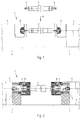
- FIG. 1 and 2 show, purely schematically, a processing machine 1 for a workpiece 2, in particular for an intaglio cylinder, with two slidably mounted on a respective machine slide 4 in the direction of the longitudinal axis 3 of the processing machine 1 Shaft bearing 5 shown.
- the shaft ends 6 of the gravure cylinder 2 are placed on two angular lifting arms 7, which can be moved hydraulically or pneumatically within the shaft bearings 5 in the longitudinal axis 3 of the processing machine 1 with a cylinder and piston unit (not shown here).
- the gravure cylinder 2 with its shaft ends 6 is placed on the angular lifting arms 7 from above by means of a lifting crane indicated by the arrow 9.
- a chuck 10 for receiving the shaft ends 6 is provided in the respective shaft bearing 5.
- the two machine slides 4 are pushed against the gravure cylinder 2 held on the lifting arms 7, so that the shaft ends 6 thereof can be picked up and clamped in by the chucks 10.
- the lifting arms 7 are withdrawn within the respective shaft bearing 5, i.e. moved away from the gravure cylinder 2 by means of piston and cylinder units, not shown, so that the shaft ends 6 are only held by the chucks 10 (state shown in FIG. 2).
- FIGS. 4 to 7 represent a view or cross sections according to the arrows and section lines E to C in FIGS. 3 and 10 and FIGS. 8 and 9 show the cross sections along section lines B and A in FIG. 3.
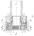
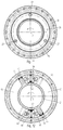
- the chuck 10 consists of a clamping head 11 with clamping parts 12a which are adjustably mounted, arcuately curved and have a rectangular cross section, 12b, 12c.
- the clamping head 11 also has an intermediate ring 13 and an outer flange 14, which are fastened to one another by means of screws 15 and clamp three guide elements or clamping disk segments 16 arranged circumferentially about the longitudinal axis 3 in a groove 17 formed between them.
- This clamping head 11 is fastened on the end face to a spindle flange 18 of a spindle 19 which can be rotated in the shaft bearing 5 (see FIG. 1) by means of screws 20.
- a rotary drive tube 21 is rotatably supported by means of a roller or ball bearing 22 and driven by two toothed racks 23 located opposite one another and which can be moved back and forth in the spindle flange. These racks 23 engage in an external toothing 24 on the circumference of the rotary drive tube 21.
- an annular disk 26 is fastened in a rotationally drivable manner to the rotary drive tube 21 by means of serration 25.
- This ring disk 26 is rotatably mounted on a roller bearing 26a within the intermediate ring 13 and carries three end faces against the clamping parts 12 and bearing or driving bolts 27 which engage therein and which are distributed in the circumferential direction of the ring disk 26 at an angle of 120 ° to one another. These driving bolts 27 form pivot axes for the clamping parts 12a, 12b and 12c. Between the spindle flange 18 and the washer 26, a bearing washer 28 is screwed onto the spindle flange 18 by means of screws 29. This bearing disk 28 is used for axially guiding the annular disk 26 between the clamping head 11 and the spindle flange 18.
- three circular arc-shaped guide grooves 30 are provided, which decrease along an arc segment with one decreasing to the longitudinal axis 3 Distance.
- a guide pin 31 engages in each guide groove 30 and is provided on the end face of a respective clamping part 12a, 12b or 12c facing the outer flange 14.
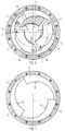
- FIG. 4 which represents the view in the direction of arrow E in FIGS. 3 and 10
- the above-mentioned guide grooves 30 are indicated in dashed lines and are clearly recognizable with their decreasing distance from the longitudinal axis 3.
- the outlines of the clamping parts 12a, 12b and 12c are also shown in dashed lines.
- the left end region 32 of a respective clamping part 12a, 12b or 12c, seen in the counterclockwise direction, is also shown in dashed lines.
- the tensioning disk segments 16 indicated by dashed lines can be seen.
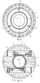
- FIGS. 5 to 8 represent the respective cross sections through the clamping head 11 along the lines DD (FIGS. 5 and 6), CC and BB.
- the guide track 33 of the respective clamping disk segments 16 is specified, which is assigned to the respective clamping part 12a, 12b or 12c.
- the clamping parts 12a, 12b and 12c have a groove 35 recessed on the outer curved surface 34, which runs along an arcuate line with a decreasing distance from the longitudinal axis 3.
- This groove 35 ends with a hump-shaped support 36, which is provided in the end region 37 of the respective clamping part 12a, 12b or 12c.
- the guidance of the hump-shaped support 36 on the guideway 33 can be clearly seen in FIG.
- the groove 35 has a greater curvature than the guide track 33 of the associated tensioning disk segment 16, which is why the groove 35 is at the bottom a counterclockwise rotation of the respective clamping part 12a, 12b or 12c will never touch the guideway 33. Therefore, only the hump-shaped support 36 rests on the guideway 33 and there is always enough play between the groove 35 and the guideway 33 (see also FIG. 6).
- the shape of the tensioning disk segments 16 with their guideways 33 can be seen above all from FIG.
- the guideways 33 advantageously run at least approximately along an Archimedean spiral with an incline of 3 ° to 8 °, in particular approximately 6.5 °.
- the arcuate inner surfaces 38 of the clamping parts 12a, 12b and 12c are of circular cylindrical design and, in the outermost rotational position, comprise the largest diameter of a shaft end 6 of the workpiece or gravure cylinder 2 (FIG. 5). With increasing rotation of the clamping parts 12a, 12b and 12c via the respective guide tracks 33, the receiving opening delimited by the arcuate inner surfaces 38 becomes smaller (see FIG. 6).
- the drive and the guidance of the toothed racks 23 within the spindle flange 18 can be seen in FIG.
- These racks 23 are each moved by a double-acting piston and cylinder unit 39 in the drawing to the left or to the right.
- the connections with a hydraulic or pneumatic pump, feed lines and associated valves are generally known and are therefore not shown here.
- the rotary drive tube 21 is rotated with its external toothing 24 in a counterclockwise or clockwise direction. This also causes a rotation of the on the Washer 26 fastened driving bolts 27, and thus rotation of the clamping parts 12a, 12b and 12c along their respective guideways 33 on the tensioning disk segments 16.
- the guide pins 31 in the guide grooves 30 (FIG.
- the machine slides 4 are moved inwards, whereby the two chucks 10 encompass the shaft ends 6.
- the clamping parts 12 are rotated by means of the adjustment mechanism described above by turning the driving pins 27 and guided by the hump-shaped supports 36 resting on the guide track 33 around the driving pins 27 until the shaft end 6 is clamped between the clamping parts 12. Because of the shape of the guideways 33 as an Archimedean spiral, there is a self-locking between a respective clamping part 12a, 12b and 12c and the cylindrical shaft end 6, so that the shaft ends 6 can no longer be released without counter-rotation of the clamping parts 12a, 12b and 12c.
- FIGS. 10 to 12 A variant of the drive for the rotary drive tube 21 is shown in FIGS. 10 to 12.
- the clamping head 11 of the chuck 10 of this variant is completely identical to that shown in FIGS. 3 to 9, which is why a further explanation of the corresponding components can be dispensed with here.
- the racks 23 and the piston and cylinder units 39 of the first embodiment are replaced here by a pure hydraulic or pneumatic drive.
- the rotary drive tube 21 is provided with two radial, diametrically opposed rotary vanes 40 which extend against the base 41 of an annular groove 42 which is provided in the spindle flange 18 and a second intermediate ring 43 abutting against it.
- the rotary wings 40 are provided at the end with a cap-shaped seal 44 and are each rotatable within an annular chamber 45, which are formed by two diametrically opposed radial separating elements 46 in the annular groove 42. These separating elements 46 are each sealed against the rotary drive tube 21 by means of a T-shaped seal 47. Furthermore, stops 48 are provided in the circumferential direction on the sides of these separating elements in order to prevent rotation limit the rotary wing 40. The other end position of the rotary wing 40 is shown in dashed lines.
- the rotary blades 40 are now acted upon by a hydraulic or pneumatic fluid which is pumped into one of the two sections or subspaces of the annular chamber 45 formed between the rotary blade 40 and the separating elements 46.
- a hydraulic or pneumatic fluid which is pumped into one of the two sections or subspaces of the annular chamber 45 formed between the rotary blade 40 and the separating elements 46.
- the principle of operation of the shaft bearing according to the invention can also be achieved if the tensioning disk segments 16 are rotatably mounted relative to the clamping parts 12a, 12b and 12c which are fastened to the tensioning head 11 and can be pivoted about a fixed pivot axis.
- the design of the inner surfaces 38 of the clamping parts 12a, 12b and 12c does not necessarily have to be arcuate, but can at least partially be wedge-shaped in order to achieve the aforementioned self-locking.
Landscapes
- Engineering & Computer Science (AREA)
- Mechanical Engineering (AREA)
- Gripping On Spindles (AREA)
- Rotary Presses (AREA)
- Manufacture Or Reproduction Of Printing Formes (AREA)
Applications Claiming Priority (2)
| Application Number | Priority Date | Filing Date | Title |
|---|---|---|---|
| CH1180/95 | 1995-04-25 | ||
| CH118095 | 1995-04-25 |
Publications (2)
| Publication Number | Publication Date |
|---|---|
| EP0739671A2 true EP0739671A2 (fr) | 1996-10-30 |
| EP0739671A3 EP0739671A3 (fr) | 1997-07-23 |
Family
ID=4204372
Family Applications (1)
| Application Number | Title | Priority Date | Filing Date |
|---|---|---|---|
| EP96105833A Withdrawn EP0739671A3 (fr) | 1995-04-25 | 1996-04-13 | Support d'un arbre |
Country Status (3)
| Country | Link |
|---|---|
| US (1) | US5785325A (fr) |
| EP (1) | EP0739671A3 (fr) |
| JP (1) | JP2957945B2 (fr) |
Families Citing this family (10)
| Publication number | Priority date | Publication date | Assignee | Title |
|---|---|---|---|---|
| JP4119583B2 (ja) * | 1999-10-06 | 2008-07-16 | 株式会社東興 | 差動四爪チャック |
| US8292305B2 (en) * | 2009-08-04 | 2012-10-23 | Chin-Chiu Chen | Adjustable magnetism shelter of a cutter holder |
| CN102581328B (zh) * | 2012-03-14 | 2013-12-04 | 赵长军 | 前置摆动缸式中空液压卡盘 |
| US9180268B2 (en) * | 2012-05-01 | 2015-11-10 | Covidien Lp | Cuff pressure measurement device for a tracheal tube |
| CN104043850A (zh) * | 2014-06-27 | 2014-09-17 | 洛阳一米机械有限公司 | 一种浮动夹具 |
| CN104525995A (zh) * | 2014-12-30 | 2015-04-22 | 东莞市佛尔盛机电科技有限公司 | 一种高压风机叶轮的加工专用夹具 |
| DE102015121391A1 (de) * | 2015-12-09 | 2017-06-14 | Röhm Gmbh | Spannmittel |
| CN111112662B (zh) * | 2019-12-24 | 2021-02-05 | 洛阳先驱自动化设备有限公司 | 一种薄壁工件加工用外夹紧装置 |
| CN111336363B (zh) * | 2020-03-21 | 2021-06-25 | 大连理工大学 | 环抱式圆柱结构件外表面固定装置及其工作方式 |
| DE102021109210B4 (de) * | 2021-04-13 | 2024-07-25 | Pva Tepla Analytical Systems Gmbh | Wafer-Chuck zur Handhabung und Durchschallung eines Wafers in einem akustischen Rastermikroskop, Verwendung eines Wafer-Chucks und Waferprozessvorrichtung mit einem Wafer-Chuck |
Family Cites Families (17)
| Publication number | Priority date | Publication date | Assignee | Title |
|---|---|---|---|---|
| DE350131C (de) * | 1922-03-14 | Curt Hisserich | Vorrichtung zum Abfraesen von Graten an Rohrenden | |
| DE16533C (de) * | F. AN-DREE in Berlin S., Prinzenstr. 32 | Centrirendes Spannfutter | ||
| US1187920A (en) * | 1910-01-03 | 1916-06-20 | Pratt & Whitney Co | Chuck. |
| US1770515A (en) * | 1928-10-13 | 1930-07-15 | Gisholt Machine Co | Self-gripping chuck |
| DE599708C (de) * | 1931-11-08 | 1934-07-07 | Otto Max Mueller | Spannfutter, insbesondere fuer Werkzeugmaschinen |
| US2154908A (en) * | 1937-06-25 | 1939-04-18 | Baird Machine Co | Chuck |
| GB534447A (en) * | 1940-02-29 | 1941-03-06 | Nat Acme Co | Improvements in work holding or chucking mechanism |
| DE954024C (de) * | 1953-06-26 | 1956-12-13 | Forkardt Paul Kg | Kraftbetaetigtes Vorderendfutter fuer Drehbaenke |
| US2890889A (en) * | 1958-07-16 | 1959-06-16 | Union Mfg Co | Combination power and hand operated chuck |
| DE2020642A1 (de) * | 1969-04-29 | 1971-04-22 | Sykes Alfred Ernest | Vorrichtung fuer die Werkstueckhaltung |
| US3698729A (en) * | 1970-02-19 | 1972-10-17 | Forkardt Paul Kg | Power operated clamping device for machine tools |
| DE2604876C3 (de) * | 1976-02-07 | 1978-11-16 | Messer Griesheim Gmbh, 6000 Frankfurt | Schweißmaschine mit einem Spannfutter |
| GB1593266A (en) * | 1977-10-19 | 1981-07-15 | Wickman Mach Tool Sales Ltd | Chucks for machine tools |
| DE2848172A1 (de) * | 1978-11-07 | 1980-05-08 | Guenter Heckmann | Umlaufender spannzylinder |
| SU1087264A1 (ru) * | 1982-02-17 | 1984-04-23 | Предприятие П/Я А-7495 | Самоцентрирующее зажимное устройство |
| JPS6154522A (ja) * | 1984-08-26 | 1986-03-18 | Keisuke Takamori | 表示装置付きフアンクシヨン選択キ− |
| DE3837007A1 (de) * | 1988-10-31 | 1990-05-03 | Krupp Widia Gmbh | Spannvorrichtung zur verbindung von werkzeugkopf und werkzeughalter an werkzeugmaschinen |
-
1996
- 1996-04-13 EP EP96105833A patent/EP0739671A3/fr not_active Withdrawn
- 1996-04-25 JP JP8105543A patent/JP2957945B2/ja not_active Expired - Lifetime
- 1996-04-25 US US08/638,891 patent/US5785325A/en not_active Expired - Fee Related
Also Published As
| Publication number | Publication date |
|---|---|
| JPH08294807A (ja) | 1996-11-12 |
| JP2957945B2 (ja) | 1999-10-06 |
| EP0739671A3 (fr) | 1997-07-23 |
| US5785325A (en) | 1998-07-28 |
Similar Documents
| Publication | Publication Date | Title |
|---|---|---|
| DE60300083T2 (de) | Vorrichtung zur Überwachung des Spannzustands einer Spannvorrichtung | |
| DE4237422C2 (de) | Werkstückhaltevorrichtung für auf Werkzeugmaschinen mehrseitig zu bearbeitende Werkstücke | |
| DE69800037T2 (de) | Spannfutter | |
| EP2425917B1 (fr) | Mandrin à diaphragme | |
| EP0753368B1 (fr) | Dispositif de serrage pour la fixation relative précise de 2 pièces | |
| DE1921282B2 (de) | Werkstückaufnahme- und Antriebsvorrichtung an einer Kurbelwellenschleifmaschine | |
| DE29603602U1 (de) | Werkzeugspanneinrichtung | |
| EP0739671A2 (fr) | Support d'un arbre | |
| DE69310579T2 (de) | Werkzeug-Ein- und Ausspannvorrichtung | |
| DE10163365B4 (de) | Spannfutter zum Festspannen dünner, scheibenförmiger Werkstücke | |
| DE2754357C2 (fr) | ||
| DE102017123681C5 (de) | Fräswerkzeug zum Bearbeiten von Holz, Holzwerkstoffen, Kunststoffen oder Leichtmetallen | |
| EP1956183A1 (fr) | Tête de serrage pour un élément de tiges | |
| EP0185170B1 (fr) | Mandrin à mors pour machines à tourner pour l'usinage de pièces suivant des axes multiples | |
| DE3930154C2 (fr) | ||
| DE861043C (de) | Zweistufiges Schnellwechsel-Spannfutter fuer Werkzeugmaschinen | |
| EP1038618B1 (fr) | Tête d'outil pour un tour | |
| WO2003095132A1 (fr) | Dispositif de serrage expansible | |
| DE4308738A1 (de) | Spann- und Löseeinrichtung für Schaftwerkzeuge | |
| DE7618904U1 (de) | Spanneinrichtung an einer werkzeugmaschine | |
| DE2924573C2 (de) | Einrichtung zum selbsttätigen radialen Positionieren der Drehwerkzeuge auf Radsatzdrehmaschinen | |
| EP0353384A2 (fr) | Dispositif de serrage pour machines-outils avec un cylindre de serrage tournant | |
| DE19856562C1 (de) | Spanneinrichtung für scheibenförmige Werkstücke | |
| DE4031381C1 (fr) | ||
| DE2228654A1 (de) | Vorrichtung zum umsetzen von teilen, insbesondere werkzeugwechselvorrichtung bei werkzeugmaschinen |
Legal Events
| Date | Code | Title | Description |
|---|---|---|---|
| PUAI | Public reference made under article 153(3) epc to a published international application that has entered the european phase |
Free format text: ORIGINAL CODE: 0009012 |
|
| AK | Designated contracting states |
Kind code of ref document: A2 Designated state(s): DE FR GB IT SE |
|
| PUAL | Search report despatched |
Free format text: ORIGINAL CODE: 0009013 |
|
| ITCL | It: translation for ep claims filed |
Representative=s name: SAIC BREVETTI S.R.L. |
|
| EL | Fr: translation of claims filed | ||
| AK | Designated contracting states |
Kind code of ref document: A3 Designated state(s): DE FR GB IT SE |
|
| GBC | Gb: translation of claims filed (gb section 78(7)/1977) | ||
| 17P | Request for examination filed |
Effective date: 19980122 |
|
| 17Q | First examination report despatched |
Effective date: 19981127 |
|
| STAA | Information on the status of an ep patent application or granted ep patent |
Free format text: STATUS: THE APPLICATION IS DEEMED TO BE WITHDRAWN |
|
| 18D | Application deemed to be withdrawn |
Effective date: 20001101 |