EP0739725B1 - Schnellbefestigungssystem für Druckplattenwechsel - Google Patents
Schnellbefestigungssystem für Druckplattenwechsel Download PDFInfo
- Publication number
- EP0739725B1 EP0739725B1 EP19950500066 EP95500066A EP0739725B1 EP 0739725 B1 EP0739725 B1 EP 0739725B1 EP 19950500066 EP19950500066 EP 19950500066 EP 95500066 A EP95500066 A EP 95500066A EP 0739725 B1 EP0739725 B1 EP 0739725B1
- Authority
- EP
- European Patent Office
- Prior art keywords
- plate
- hydraulic
- printing plate
- clamp
- over
- Prior art date
- Legal status (The legal status is an assumption and is not a legal conclusion. Google has not performed a legal analysis and makes no representation as to the accuracy of the status listed.)
- Expired - Lifetime
Links
- 239000011796 hollow space material Substances 0.000 claims 2
- 239000012530 fluid Substances 0.000 description 4
- 230000006835 compression Effects 0.000 description 2
- 238000007906 compression Methods 0.000 description 2
- 230000007423 decrease Effects 0.000 description 2
- RYGMFSIKBFXOCR-UHFFFAOYSA-N Copper Chemical compound [Cu] RYGMFSIKBFXOCR-UHFFFAOYSA-N 0.000 description 1
- 229910000831 Steel Inorganic materials 0.000 description 1
- 230000004075 alteration Effects 0.000 description 1
- 230000033228 biological regulation Effects 0.000 description 1
- 229910052802 copper Inorganic materials 0.000 description 1
- 239000010949 copper Substances 0.000 description 1
- 239000000463 material Substances 0.000 description 1
- 238000000034 method Methods 0.000 description 1
- 238000010926 purge Methods 0.000 description 1
- 230000001105 regulatory effect Effects 0.000 description 1
- 239000010959 steel Substances 0.000 description 1
- 239000011800 void material Substances 0.000 description 1
Images

Classifications
-
- B—PERFORMING OPERATIONS; TRANSPORTING
- B41—PRINTING; LINING MACHINES; TYPEWRITERS; STAMPS
- B41F—PRINTING MACHINES OR PRESSES
- B41F27/00—Devices for attaching printing elements or formes to supports
- B41F27/12—Devices for attaching printing elements or formes to supports for attaching flexible printing formes
- B41F27/1218—Devices for attaching printing elements or formes to supports for attaching flexible printing formes comprising printing plate tensioning devices
- B41F27/1225—Devices for attaching printing elements or formes to supports for attaching flexible printing formes comprising printing plate tensioning devices moving in the printing plate end substantially rectilinearly
- B41F27/1231—Devices for attaching printing elements or formes to supports for attaching flexible printing formes comprising printing plate tensioning devices moving in the printing plate end substantially rectilinearly by translatory motion substantially tangential to support surface
Definitions
- DE-U-8710030 discloses a system according to the preamble of claim 1.
- the present invention is referred to a fixing and adjusting system of the printing plate to the plate cylinder in an offset press.
- the printing plate fastening systems known in the offset presses mounts the printing plate's edges into the plate cylinder using a mechanical tightening device with screws or eccentrics, tensioning later the printing plate by the movement of the clamps in the peripherical direction of the cylinder using strews or hydraulic systems.
- the present invention has the object to avoid these inconvenients, and brings a fixing and adjusting system of the printing plate to a plate cylinder of offset presses, though the use, for the fixing over the whole lenght of the printing plate ends, of the advantages offered by the hydraulic system used on the system of teeth, that locks over their whole lenght the edges of the printing plate, with a substantial reduction of the time of realization for the fixing plate operation, substantially in the preparation and final setting of the offset presses at the beginning of their work operations.
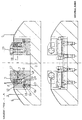
- the plate cylinder has a parallel hollow to its geometrical shaft, enough to lodge two hydraulic clamps that fixes both ends of the printing plate, that will be adjusted all around the cylinder area.
- the printing plate is introduced between the teeth of the clamp, and the actioning of the hydraulic circuit permits, in the question of one second, the fixing, over its whole lenght, of the printing plate ends, adjusting itself later the plate all along the cyilinder by any of the known methods of plate adjusting.
- the advantages deduced by this invention consists essentially, as mentioned above, of the use of the hydraulic device in order to realize the tightening and longitudinal adjusting of a printing plate to its cylinder, securing the uniform tightening over the lenght of the printing plate edges, from the point of view of time reduction and uniform tightening over the whole lenght of the printing plate ends.
- the canalization of the hydraulic fluid that arrives from the hydraulic pump, drawing 2 (36), to the main canalization, drawings 1 and 2 (7), is realized through all the lenght of the hydraulic clamp, connects with the canalization (8) and (9) that are realized in spaced intervals over the whole body (2) lenght of the hydraulic clamp.
- the fluid moves a piston (10), wich brings an U-collar (11) and an O-ring (12), over the lower tooth (4), that moves the printing plate (6) upwards and with a uniform pressure over the whole lenght of the upper tooth (5), that does not move.
- the hermeticity of the main canalization (7) all along the body (2) of the clamp, is warranted by an O-ring (17), that is intercalated between the body (2) and the upper tooth (5), and these two parts of the hydraulic clamp are fixed by screws (19), wich have warranted their hermeticity by special copper washers (18), specially used in hydraulic circuits.
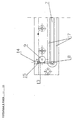
- the actioning of the hydraulic pump, as the regulating of the hydraulic pressure is detailed in the following manner, as the drawing 2;
- the bolt (26) is actioned by a hexagonal wrench turning it 90° over its shaft until a position determinated by a mechanical positioning top realized by the rod (27), that moves a shaft (28) guided over a holder (29);
- the shaft (28) is threaded to the shaft (30) wich moves the piston (31) over the pump body (32) passing the hydraulic fluid through the drilled hole (25) to the main canalization (7) of the hydraulic clamp body.
- the sealed system of the pump assy is warranted by two U-collars (33) and (34).
- U-collars (33) and (34) In order to protect the body of the pump (32) from wear of the metalic parts from wich it is made it is provided with some guides (35) of plastic material, preferably Tephlon.
- the return of the piston (31) to its rest position is accomplished by two components: a) The pressure held by the hydraulic fluid, within its run; and b) The power held by the spring (36), that warrants the return of the piston to its initial position.
- the regulation of the pressure held by the hydraulic pump is realized by the regulator (37), that turns in one or another direction, increases or decreases the distance between the shaft (28) and the shaft (30), making that the piston (31), in its compression position, increases or decreases the compression chamber (38) originating with this movement a variation of the pressure all along the whole hydraulic circuit.
Landscapes
- Supply, Installation And Extraction Of Printed Sheets Or Plates (AREA)
Claims (1)
- ES BESTEHT AUS EIN SCHNELLSPANNSCHIENEN SYSTEM FÜR OFFSETMACHINEN DRUCKPLATTEN. DIE SCHIENEN SIND AUF DER PLATTENCYLINDER EINGEBAUT UN EIN INTEGRIERTES SYSTEM BESTEHT AUS EIN PLATTENSPANNZYLINDER, ZWEI (OBERE UND UNTERE) KLAPPEN MIT ZÄHNEN IN DER PARALLELE ZU DER ZYLINDERGENERATRIZGUTTER SO BREIT WIE DIE PLATTENLÄNGE. DIESE KLAPPEN SIND SO STUDIERT UM DIE BEIDE KANNTEN DER DRUCKPLATTE ZU HALTEN, UN DIE UNTERE KLAPPE IS DURCH EIN HYDRAULISCHE HUBZYLINDER ANGETRIEBEN. SO DASS DIE HÄLT DIE PLATTE ZWICHEN DIE OBERE UND DIE UNTERE KLAPPEN.
Priority Applications (2)
| Application Number | Priority Date | Filing Date | Title |
|---|---|---|---|
| EP19950500066 EP0739725B1 (de) | 1995-04-28 | 1995-04-28 | Schnellbefestigungssystem für Druckplattenwechsel |
| DE69528040T DE69528040D1 (de) | 1995-04-28 | 1995-04-28 | Schnellbefestigungssystem für Druckplattenwechsel |
Applications Claiming Priority (1)
| Application Number | Priority Date | Filing Date | Title |
|---|---|---|---|
| EP19950500066 EP0739725B1 (de) | 1995-04-28 | 1995-04-28 | Schnellbefestigungssystem für Druckplattenwechsel |
Publications (2)
| Publication Number | Publication Date |
|---|---|
| EP0739725A1 EP0739725A1 (de) | 1996-10-30 |
| EP0739725B1 true EP0739725B1 (de) | 2002-09-04 |
Family
ID=8221651
Family Applications (1)
| Application Number | Title | Priority Date | Filing Date |
|---|---|---|---|
| EP19950500066 Expired - Lifetime EP0739725B1 (de) | 1995-04-28 | 1995-04-28 | Schnellbefestigungssystem für Druckplattenwechsel |
Country Status (2)
| Country | Link |
|---|---|
| EP (1) | EP0739725B1 (de) |
| DE (1) | DE69528040D1 (de) |
Family Cites Families (3)
| Publication number | Priority date | Publication date | Assignee | Title |
|---|---|---|---|---|
| AT296348B (de) * | 1968-05-02 | 1972-01-15 | Polygraph Leipzig | Schnellspanneinrichtung zum befestigen biegsamer druckplatten auf formzylindern |
| DD253977A1 (de) * | 1986-11-28 | 1988-02-10 | Polygraph Leipzig | Klemmvorrichtung fuer biegsame druckplatten |
| DE4214206C2 (de) * | 1992-04-30 | 1995-06-29 | Roland Man Druckmasch | Vorrichtung zum Betätigen einer Klemmschiene gegenüber der Spannschiene des Plattenzylinders einer Rotationsdruckmaschine, insbesondere Bogenoffsetdruckmaschine |
-
1995
- 1995-04-28 DE DE69528040T patent/DE69528040D1/de not_active Expired - Lifetime
- 1995-04-28 EP EP19950500066 patent/EP0739725B1/de not_active Expired - Lifetime
Also Published As
| Publication number | Publication date |
|---|---|
| EP0739725A1 (de) | 1996-10-30 |
| DE69528040D1 (de) | 2002-10-10 |
Similar Documents
| Publication | Publication Date | Title |
|---|---|---|
| EP1379385B1 (de) | Vorrichtungen zum einstellen eines anpressdrucks einer verstellbar gelagerten walze | |
| DD216421A5 (de) | Verfahren und vorrichtung zur befestigung und justierung einer druckplatte auf einem plattenzylinder einer rotationsdruckmaschine | |
| EP1539495B1 (de) | Vorrichtungen und verfahren zum einstellen des anpressdrucks einer verstellbar gelagerten walze | |
| EP0739725B1 (de) | Schnellbefestigungssystem für Druckplattenwechsel | |
| EP0596337B1 (de) | Vorrichtung für das registergerechte Anlegen von Druckplatten auf dem Plattenzylinder von Druckmaschinen | |
| RU1830004C (ru) | Устройство дл регулировани приводки | |
| EP1246727B1 (de) | Verfahren zum Einstellen einer Walze einer Druckmaschine | |
| EP0739726B1 (de) | Vorrichtung zum Spannen einer Druckplatte auf einem Plattenzylinder von Rotationsdruckmaschinen | |
| EP0142874B1 (de) | Zum Aufspannen von Stichdruckplatten eingerichteter Formzylinder für Rollendruckmaschinen | |
| AT519U1 (de) | Spritzgiessmaschine | |
| EP0087041A1 (de) | Spannklemme zum Montieren von Druckplatten oder dgl. auf dem Arbeitstisch von Stempelpressen | |
| CA2073118A1 (en) | Intaglio printing machine | |
| EP1413433A1 (de) | Druckwerk einer Rollenrotationsdruckmaschine für Zeitungsdruck | |
| DE19716424B4 (de) | Einrichtung zum Vermeiden des Ablegens von Farbe auf Zylindern von Druckmaschinen | |
| EP0631868B1 (de) | Vorrichtung zum passgenauen Spannen von Druckplatten auf dem Plattenzylinder von Druckmaschinen | |
| EP0703018A1 (de) | Mechanische oder hydraulische Presse | |
| DD242027A1 (de) | Zusatzeinrichtung zur druckumstellung | |
| DE202006012655U1 (de) | Spannplatte für einen Federspanner und Federspanner | |
| US6588815B1 (en) | Transfer press embodying a piston-cylinder assembly to effect gripping activity | |
| DE3115141A1 (de) | Vorrichtung zum diagonalverstellen eines zylinders einer druckmaschine, vorzugsweise des plattenzylinders einer bogenrotations-offsetdruckmaschine | |
| JP2549789Y2 (ja) | 開頭式圧延機キャップの固定装置 | |
| FI71605B (fi) | Hydraulcylinder | |
| DE7431974U (de) | Schraubenzieher für Zylinderschrauben mit Innensechskant | |
| EP0331777A1 (de) | Spannvorrichtung zur Befestigung eines Aufzuges am Zylinder einer Rotationsdruckmaschine | |
| EP0653257B1 (de) | Schmiedemaschine |
Legal Events
| Date | Code | Title | Description |
|---|---|---|---|
| PUAI | Public reference made under article 153(3) epc to a published international application that has entered the european phase |
Free format text: ORIGINAL CODE: 0009012 |
|
| AK | Designated contracting states |
Kind code of ref document: A1 Designated state(s): BE DE ES FR |
|
| 17P | Request for examination filed |
Effective date: 19970421 |
|
| 17Q | First examination report despatched |
Effective date: 19990607 |
|
| GRAG | Despatch of communication of intention to grant |
Free format text: ORIGINAL CODE: EPIDOS AGRA |
|
| GRAG | Despatch of communication of intention to grant |
Free format text: ORIGINAL CODE: EPIDOS AGRA |
|
| GRAH | Despatch of communication of intention to grant a patent |
Free format text: ORIGINAL CODE: EPIDOS IGRA |
|
| GRAH | Despatch of communication of intention to grant a patent |
Free format text: ORIGINAL CODE: EPIDOS IGRA |
|
| RAP1 | Party data changed (applicant data changed or rights of an application transferred) |
Owner name: TGA INGENIERIA GRAFICA, S.L. |
|
| GRAA | (expected) grant |
Free format text: ORIGINAL CODE: 0009210 |
|
| AK | Designated contracting states |
Kind code of ref document: B1 Designated state(s): BE DE ES FR |
|
| PG25 | Lapsed in a contracting state [announced via postgrant information from national office to epo] |
Ref country code: FR Free format text: LAPSE BECAUSE OF NON-PAYMENT OF DUE FEES Effective date: 20020904 Ref country code: BE Free format text: LAPSE BECAUSE OF FAILURE TO SUBMIT A TRANSLATION OF THE DESCRIPTION OR TO PAY THE FEE WITHIN THE PRESCRIBED TIME-LIMIT Effective date: 20020904 |
|
| REF | Corresponds to: |
Ref document number: 69528040 Country of ref document: DE Date of ref document: 20021010 |
|
| PG25 | Lapsed in a contracting state [announced via postgrant information from national office to epo] |
Ref country code: DE Free format text: LAPSE BECAUSE OF FAILURE TO SUBMIT A TRANSLATION OF THE DESCRIPTION OR TO PAY THE FEE WITHIN THE PRESCRIBED TIME-LIMIT Effective date: 20021205 |
|
| PG25 | Lapsed in a contracting state [announced via postgrant information from national office to epo] |
Ref country code: ES Free format text: LAPSE BECAUSE OF FAILURE TO SUBMIT A TRANSLATION OF THE DESCRIPTION OR TO PAY THE FEE WITHIN THE PRESCRIBED TIME-LIMIT Effective date: 20030328 |
|
| EN | Fr: translation not filed | ||
| PLBE | No opposition filed within time limit |
Free format text: ORIGINAL CODE: 0009261 |
|
| STAA | Information on the status of an ep patent application or granted ep patent |
Free format text: STATUS: NO OPPOSITION FILED WITHIN TIME LIMIT |
|
| 26N | No opposition filed |
Effective date: 20030605 |