EP0740023A1 - Werkzeugarm mit seitlichem Doppelgelenk - Google Patents
Werkzeugarm mit seitlichem Doppelgelenk Download PDFInfo
- Publication number
- EP0740023A1 EP0740023A1 EP96420140A EP96420140A EP0740023A1 EP 0740023 A1 EP0740023 A1 EP 0740023A1 EP 96420140 A EP96420140 A EP 96420140A EP 96420140 A EP96420140 A EP 96420140A EP 0740023 A1 EP0740023 A1 EP 0740023A1
- Authority
- EP
- European Patent Office
- Prior art keywords
- tool
- arrow
- articulation
- arm
- axis
- Prior art date
- Legal status (The legal status is an assumption and is not a legal conclusion. Google has not performed a legal analysis and makes no representation as to the accuracy of the status listed.)
- Ceased
Links
- 238000006073 displacement reaction Methods 0.000 claims description 14
- 230000008878 coupling Effects 0.000 abstract 2
- 238000010168 coupling process Methods 0.000 abstract 2
- 238000005859 coupling reaction Methods 0.000 abstract 2
- 230000006978 adaptation Effects 0.000 description 2
- 238000010586 diagram Methods 0.000 description 2
Images


Classifications
-
- E—FIXED CONSTRUCTIONS
- E02—HYDRAULIC ENGINEERING; FOUNDATIONS; SOIL SHIFTING
- E02F—DREDGING; SOIL-SHIFTING
- E02F3/00—Dredgers; Soil-shifting machines
- E02F3/04—Dredgers; Soil-shifting machines mechanically-driven
- E02F3/28—Dredgers; Soil-shifting machines mechanically-driven with digging tools mounted on a dipper- or bucket-arm, i.e. there is either one arm or a pair of arms, e.g. dippers, buckets
- E02F3/30—Dredgers; Soil-shifting machines mechanically-driven with digging tools mounted on a dipper- or bucket-arm, i.e. there is either one arm or a pair of arms, e.g. dippers, buckets with a dipper-arm pivoted on a cantilever beam, i.e. boom
- E02F3/307—Dredgers; Soil-shifting machines mechanically-driven with digging tools mounted on a dipper- or bucket-arm, i.e. there is either one arm or a pair of arms, e.g. dippers, buckets with a dipper-arm pivoted on a cantilever beam, i.e. boom the boom and the dipper-arm being connected so as to permit relative movement in more than one plane
-
- E—FIXED CONSTRUCTIONS
- E02—HYDRAULIC ENGINEERING; FOUNDATIONS; SOIL SHIFTING
- E02F—DREDGING; SOIL-SHIFTING
- E02F3/00—Dredgers; Soil-shifting machines
- E02F3/04—Dredgers; Soil-shifting machines mechanically-driven
- E02F3/28—Dredgers; Soil-shifting machines mechanically-driven with digging tools mounted on a dipper- or bucket-arm, i.e. there is either one arm or a pair of arms, e.g. dippers, buckets
- E02F3/30—Dredgers; Soil-shifting machines mechanically-driven with digging tools mounted on a dipper- or bucket-arm, i.e. there is either one arm or a pair of arms, e.g. dippers, buckets with a dipper-arm pivoted on a cantilever beam, i.e. boom
- E02F3/302—Dredgers; Soil-shifting machines mechanically-driven with digging tools mounted on a dipper- or bucket-arm, i.e. there is either one arm or a pair of arms, e.g. dippers, buckets with a dipper-arm pivoted on a cantilever beam, i.e. boom with an additional link
-
- E—FIXED CONSTRUCTIONS
- E02—HYDRAULIC ENGINEERING; FOUNDATIONS; SOIL SHIFTING
- E02F—DREDGING; SOIL-SHIFTING
- E02F3/00—Dredgers; Soil-shifting machines
- E02F3/04—Dredgers; Soil-shifting machines mechanically-driven
- E02F3/28—Dredgers; Soil-shifting machines mechanically-driven with digging tools mounted on a dipper- or bucket-arm, i.e. there is either one arm or a pair of arms, e.g. dippers, buckets
- E02F3/30—Dredgers; Soil-shifting machines mechanically-driven with digging tools mounted on a dipper- or bucket-arm, i.e. there is either one arm or a pair of arms, e.g. dippers, buckets with a dipper-arm pivoted on a cantilever beam, i.e. boom
- E02F3/301—Dredgers; Soil-shifting machines mechanically-driven with digging tools mounted on a dipper- or bucket-arm, i.e. there is either one arm or a pair of arms, e.g. dippers, buckets with a dipper-arm pivoted on a cantilever beam, i.e. boom with more than two arms (boom included), e.g. two-part boom with additional dipper-arm
-
- E—FIXED CONSTRUCTIONS
- E02—HYDRAULIC ENGINEERING; FOUNDATIONS; SOIL SHIFTING
- E02F—DREDGING; SOIL-SHIFTING
- E02F3/00—Dredgers; Soil-shifting machines
- E02F3/04—Dredgers; Soil-shifting machines mechanically-driven
- E02F3/28—Dredgers; Soil-shifting machines mechanically-driven with digging tools mounted on a dipper- or bucket-arm, i.e. there is either one arm or a pair of arms, e.g. dippers, buckets
- E02F3/30—Dredgers; Soil-shifting machines mechanically-driven with digging tools mounted on a dipper- or bucket-arm, i.e. there is either one arm or a pair of arms, e.g. dippers, buckets with a dipper-arm pivoted on a cantilever beam, i.e. boom
- E02F3/32—Dredgers; Soil-shifting machines mechanically-driven with digging tools mounted on a dipper- or bucket-arm, i.e. there is either one arm or a pair of arms, e.g. dippers, buckets with a dipper-arm pivoted on a cantilever beam, i.e. boom working downwardly and towards the machine, e.g. with backhoes
Definitions
- the present invention relates to an improvement made to public works machines comprising a self-propelled chassis on which is mounted a turret carrying work equipment.
- It relates more particularly to an improvement made to the machines of the type subject of FR-A-2 532 671 and whose work equipment has a structure such that it makes it possible to work either as a loader or excavator by simple change of work tool.
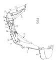
- Figure 1 attached schematically illustrates the general structure of such a machine used as an excavator.
- the work equipment designated by the general reference (1), is composed of four articulated and angularly deployable elements relative to each other, namely an arrow (2), a spout arrow (3), an arm (4) at the end of which is mounted the tool consisting of a bucket (5).
- This equipment is mounted on a turret (6) carried by a conventional vehicle preferably comprising a frame articulated in two parts, the engine being mounted on the rear chassis and the driving position and the work equipment (1) being , meanwhile, mounted side by side on the turret (6) associated with the front chassis.
- the various elements of the equipment are interconnected by an articulation allowing their angular positioning to be modified with respect to each other around horizontal pivot axes, the displacement being obtained by means of jacks.
- the boom (2) is articulated relative to the turret (6) and its position is adjusted by the boom cylinder (7) by means of two arms (8,9).
- the arrow spout (3) is connected to the other end (10) of the arrow (2) and the angular position ⁇ of these two elements (2,3) is adjusted by means of the jack (11) called “jack of arrowhead ".
- the arm (4) is articulated at the end (12) of the arrow spout (3) and the angle ⁇ between these two elements is adjusted by means of a third cylinder (13) called “cylinder of arms ".
- the bucket (5) is mounted at the end (17) of the arm (4) and its position is adjusted by a fourth cylinder (15) called "bucket cylinder".
- control of the various cylinders can be either individual, or possibly carried out in accordance with the teachings of application PCT / FR 95/01286.
- the tool (5) is therefore moved in space on the one hand by modifying the positioning of the various elements forming the work equipment (1) by pivoting about a horizontal axis of the joint. connecting the elements together and to the carrier, and, on the other hand, by rotation of the turret (6) which makes it possible to work as well in the axis of the vehicle, as on both sides of the latter at any angle.
- Such a type of machine is therefore designed to allow work to be carried out while keeping the various elements of the work equipment in line with one another, in the same vertical plane, the axes of articulation being parallel to the ground. and between them.
- a structure poses problems when it is desired to work offset, a possibility which has been obtained to date by mounting the arm jack (13) by means of cardan joints.
- the arm jack (13) poses problems, since this causes the cylinder to rotate and consequently wear out.
- the cylinder forms an angle relative to the element it controls, which results in a decrease in its efficiency.
- the device according to the invention is characterized in that at least the tool-carrying arm is connected to the element which precedes it by means of a double articulation allowing on the one hand an angular displacement around a horizontal axis , and, on the other hand, a lateral angular displacement around an axis passing in a plane orthogonal to the horizontal pivot axis, the control of this lateral displacement being obtained by means of a jack mounted laterally with respect to to the support element and which causes the pivoting of the double articulation, the jack controlling the angular movement around a horizontal axis of the tool-carrying arm, for its part, bearing on this articulation in front of the pivoting axis lateral.
- the double articulation according to the invention is at least between the arrow spout and the tool arm, the articulation between the end of the arrow and that of the arrow spout can be simple.
- the two articulations provided at each end of the arrow spout will be produced in accordance with the invention so as to be able to carry out a double offset.
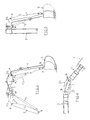
- the machine according to the invention therefore comprises work equipment (1) composed of four angularly articulated elements, deployable with respect to each other, namely a boom (2), a boom spout (3), an arm (4) at the end of which is mounted the tool consisting of a bucket (5) .
- This equipment is mounted on a turret (6) carried by a conventional vehicle.
- the boom (2) is articulated with respect to the turret (6) and its position is adjusted by the boom cylinder (7) by means of two arms (8,9).
- the boom spout (3) is connected to the end (10) of the boom (2) and the angular position ⁇ of these two elements (2,3) is adjusted by means of the boom spout cylinder (11).
- the arm (4) is articulated at the end (12) of the arrow spout (3) and the angle ⁇ between these two elements is adjusted by means of a third jack (13).
- the bucket (5) is mounted at the end (14) of the arm (4) and its position is adjusted by a fourth cylinder (15) called "bucket cylinder".
- At least the arm (4) is connected to the element which precedes it, therefore in the present case to the arrow spout (3) by means of a double articulation designated by the general reference ( 20) and which allows on the one hand, the angular displacement around the horizontal axis A, and, on the other hand, a lateral angular displacement around an axis B passing in a plane orthogonal to the horizontal pivot axis AT.
- the work equipment is preferably designed as illustrated in Figures 3 to 6 so that the connection between the end (10) of the arrow (2) and the end of the arrow spout (3) is made in a similar manner.
- the control of the lateral displacement is obtained by means of a jack (22) mounted laterally with respect to the jib spout (3) and which acts on the double articulation.
- the jacks (11,13) controlling the angular displacements around the horizontal axes A take, for their part, support on the double articulation (20) in front of the lateral pivot axis B, which allows an action in line even during a work in offset.
- the solution according to the invention has very many advantages among which we can cite in particular, when the machine allows to carry out a double offset, to have an additional angular position for the tool (6) making it possible to bypass obstacles.
Landscapes
- Engineering & Computer Science (AREA)
- Mechanical Engineering (AREA)
- Mining & Mineral Resources (AREA)
- Civil Engineering (AREA)
- General Engineering & Computer Science (AREA)
- Structural Engineering (AREA)
- Operation Control Of Excavators (AREA)
- Forklifts And Lifting Vehicles (AREA)
- Shovels (AREA)
- Jib Cranes (AREA)
Applications Claiming Priority (2)
| Application Number | Priority Date | Filing Date | Title |
|---|---|---|---|
| FR9505184A FR2733525B1 (fr) | 1995-04-25 | 1995-04-25 | Engin de travaux publics dont l'outil de travail est monte a l'extremite d'un bras articule |
| FR9505184 | 1995-04-25 |
Publications (1)
| Publication Number | Publication Date |
|---|---|
| EP0740023A1 true EP0740023A1 (de) | 1996-10-30 |
Family
ID=9478586
Family Applications (1)
| Application Number | Title | Priority Date | Filing Date |
|---|---|---|---|
| EP96420140A Ceased EP0740023A1 (de) | 1995-04-25 | 1996-04-24 | Werkzeugarm mit seitlichem Doppelgelenk |
Country Status (7)
| Country | Link |
|---|---|
| US (1) | US5661917A (de) |
| EP (1) | EP0740023A1 (de) |
| JP (1) | JPH08302725A (de) |
| KR (1) | KR960037990A (de) |
| CN (1) | CN1143139A (de) |
| CA (1) | CA2174789A1 (de) |
| FR (1) | FR2733525B1 (de) |
Cited By (3)
| Publication number | Priority date | Publication date | Assignee | Title |
|---|---|---|---|---|
| EP1798344A4 (de) * | 2004-09-29 | 2011-02-23 | Hitachi Construction Machinery | Arbeitsvorrichtung für baumaschinen |
| EP2639360A2 (de) | 2008-07-14 | 2013-09-18 | Hudson Bay Holding B.V. | Mobile Vorrichtung |
| DE102014000027A1 (de) | 2014-01-04 | 2014-10-30 | Johannes Burde | Teleskopsystem für die Integration in Monoblock- und Verstellausleger für das Verfahren des Stiel- und Hauptlagers |
Families Citing this family (15)
| Publication number | Priority date | Publication date | Assignee | Title |
|---|---|---|---|---|
| JP3775687B2 (ja) * | 1996-08-15 | 2006-05-17 | 日立建機株式会社 | 3関節型掘削機の操作制御装置 |
| ATE445047T1 (de) | 1998-08-31 | 2009-10-15 | Yanmar Co Ltd | Erdbewegungsmaschine mit sehr kleinem drehradius |
| US6409457B1 (en) * | 1999-10-15 | 2002-06-25 | George Korycan | Work vehicle |
| DE10321070B3 (de) * | 2003-05-10 | 2004-11-04 | O & K Orenstein & Koppel Gmbh | Geteilter Auslegearm für Bagger |
| US20080020867A1 (en) * | 2003-08-28 | 2008-01-24 | Callaway Golf Company | Golfer's impact properties during a golf swing |
| WO2005035882A2 (en) * | 2003-10-03 | 2005-04-21 | The Charles Machine Works, Inc. | Multi-function work machine |
| US7698838B1 (en) * | 2005-11-09 | 2010-04-20 | Strayhorn David W | Hoe equipped excavator having increased range |
| US9777459B2 (en) | 2012-07-31 | 2017-10-03 | Solar Foundations Usa, Inc | Attachment for a skid steer loader and method of use thereof |
| CN104563176B (zh) * | 2015-01-15 | 2017-11-28 | 王学义 | 装载机的拨料装置 |
| CN108118730A (zh) * | 2016-11-29 | 2018-06-05 | 广西大学 | 一种用于装配作业的伺服驱动三活动度连杆机构机械手臂 |
| CN106759564A (zh) * | 2016-12-30 | 2017-05-31 | 徐州徐工挖掘机械有限公司 | 一种挖掘机隧道用偏转式工作装置结构 |
| CN108702898A (zh) * | 2018-05-30 | 2018-10-26 | 泉州永春佳鼎农业机械有限公司 | 一种用于农业种植挖沟的移动设备 |
| DE102019100075B3 (de) * | 2019-01-03 | 2020-03-19 | Mecalac Baumaschinen GmbH | Radlader |
| CN111058503A (zh) * | 2019-12-13 | 2020-04-24 | 谢志坚 | 一种具有挖铲功能的水利工程清淤设备 |
| NL2024981B1 (en) * | 2020-02-24 | 2021-10-14 | Hudson I P B V | Electric drive of mobile apparatus |
Citations (3)
| Publication number | Priority date | Publication date | Assignee | Title |
|---|---|---|---|---|
| GB2086347A (en) * | 1980-11-04 | 1982-05-12 | Vema Spa | Articulated arm for excavator machines |
| JPS58135232A (ja) * | 1982-02-03 | 1983-08-11 | Ishikawajima Harima Heavy Ind Co Ltd | 掘削機 |
| GB2222998A (en) * | 1988-09-22 | 1990-03-28 | Kubota Ltd | Homing control for backhoe bucket |
Family Cites Families (11)
| Publication number | Priority date | Publication date | Assignee | Title |
|---|---|---|---|---|
| US3099358A (en) * | 1960-08-01 | 1963-07-30 | Int Harvester Co | Means for shifting the axis of boom means or the like |
| FR1546526A (fr) * | 1967-06-21 | 1968-11-22 | Poclain Sa | Perfectionnements aux engins de manutention à tourelle |
| FR2031763A5 (de) * | 1969-02-06 | 1970-11-20 | Poclain Sa | |
| SE437050B (sv) * | 1982-06-04 | 1985-02-04 | Ingemar Eriksson | Till en lastmaskin applicerbart grevaggregat for mindre grevarbeten |
| FR2532671A1 (fr) * | 1982-09-08 | 1984-03-09 | Pingon Pierre De | Chargeur-excavateur a un seul equipement de travail |
| JPS60169352U (ja) * | 1984-04-18 | 1985-11-09 | 株式会社 竹内製作所 | 掘削作業装置 |
| DE3435981A1 (de) * | 1984-10-01 | 1986-04-17 | Macmoter S.P.A., Modigliana | Kompaktbagger |
| DE3533427A1 (de) * | 1985-09-19 | 1987-03-26 | Schaeff Karl Gmbh & Co | Seitenversatzeinrichtung fuer eine baggerkonsole |
| DE3843753A1 (de) * | 1988-12-24 | 1990-06-28 | Schaeff Karl Gmbh & Co | Baggerarm |
| JPH04254625A (ja) * | 1990-11-30 | 1992-09-09 | Hitachi Constr Mach Co Ltd | オフセットブーム式建設機械 |
| FR2707956B1 (fr) * | 1993-07-01 | 1995-10-06 | Thibault Jacques | Emballage souple à double fermeture, notamment pour la présentation et l'expédition d'objets. |
-
1995
- 1995-04-25 FR FR9505184A patent/FR2733525B1/fr not_active Expired - Fee Related
-
1996
- 1996-04-23 CA CA002174789A patent/CA2174789A1/fr not_active Abandoned
- 1996-04-24 CN CN96108977A patent/CN1143139A/zh active Pending
- 1996-04-24 EP EP96420140A patent/EP0740023A1/de not_active Ceased
- 1996-04-24 JP JP8102938A patent/JPH08302725A/ja not_active Withdrawn
- 1996-04-25 KR KR1019960014087A patent/KR960037990A/ko not_active Withdrawn
- 1996-04-25 US US08/626,430 patent/US5661917A/en not_active Expired - Fee Related
Patent Citations (3)
| Publication number | Priority date | Publication date | Assignee | Title |
|---|---|---|---|---|
| GB2086347A (en) * | 1980-11-04 | 1982-05-12 | Vema Spa | Articulated arm for excavator machines |
| JPS58135232A (ja) * | 1982-02-03 | 1983-08-11 | Ishikawajima Harima Heavy Ind Co Ltd | 掘削機 |
| GB2222998A (en) * | 1988-09-22 | 1990-03-28 | Kubota Ltd | Homing control for backhoe bucket |
Non-Patent Citations (1)
| Title |
|---|
| PATENT ABSTRACTS OF JAPAN vol. 7, no. 250 (M - 254)<1395> 8 November 1983 (1983-11-08) * |
Cited By (3)
| Publication number | Priority date | Publication date | Assignee | Title |
|---|---|---|---|---|
| EP1798344A4 (de) * | 2004-09-29 | 2011-02-23 | Hitachi Construction Machinery | Arbeitsvorrichtung für baumaschinen |
| EP2639360A2 (de) | 2008-07-14 | 2013-09-18 | Hudson Bay Holding B.V. | Mobile Vorrichtung |
| DE102014000027A1 (de) | 2014-01-04 | 2014-10-30 | Johannes Burde | Teleskopsystem für die Integration in Monoblock- und Verstellausleger für das Verfahren des Stiel- und Hauptlagers |
Also Published As
| Publication number | Publication date |
|---|---|
| JPH08302725A (ja) | 1996-11-19 |
| FR2733525B1 (fr) | 1997-07-04 |
| US5661917A (en) | 1997-09-02 |
| CA2174789A1 (fr) | 1996-10-26 |
| KR960037990A (ko) | 1996-11-19 |
| CN1143139A (zh) | 1997-02-19 |
| FR2733525A1 (fr) | 1996-10-31 |
Similar Documents
| Publication | Publication Date | Title |
|---|---|---|
| FR2733525A1 (fr) | Engin de travaux publics dont l'outil de travail est monte a l'extremite d'un bras articule | |
| FR2595107A1 (fr) | Vehicule de type pelleteuse a pivotement complet a rayon reduit pour faciliter les operations dans un site resserre | |
| FR2635130A1 (de) | ||
| FR2615219A1 (fr) | Vehicule a pelle retrocaveuse | |
| EP0997062B1 (de) | Landmaschine | |
| FR2624898A1 (fr) | Appareil de bulldozer pour engin de chantier comprenant plusieurs verins de compensation des forces developpees pendant les operations de terrassement, excavation ou autres | |
| FR2493370A1 (fr) | Bras articule pour engin d'excavation | |
| EP0700795B1 (de) | Markierungsgerät zum Aufbringen von Zweidimensionellen-Identifikationszeichen auf der Oberfläche eines Gegenstandes | |
| FR2816166A1 (fr) | Machine robotisee de taille d'arbustes ou d'arbres tels que des arbres fruitiers | |
| US5634523A (en) | Blade device | |
| FR2499535A1 (fr) | Procede et dispositif pour la commande de la fleche d'un appareil de levage | |
| FR2532671A1 (fr) | Chargeur-excavateur a un seul equipement de travail | |
| FR2701627A1 (fr) | Dispositif adaptable sur véhicule automoteur du genre tracteur, notamment pour l'entretien des espaces verts, talus et accotements. | |
| EP2959759A1 (de) | Landwirtschaftliche maschine, die mit einer zentriervorrichtung ausgestattet ist | |
| FR2727998A1 (fr) | Engin de travaux publics de type chargeur, dont la cabine de pilotage ainsi que l'equipement de travail sont montes sur une tourelle | |
| FR3032595A1 (fr) | Machine de coupe de vegetaux et vehicule automobile comprenant une telle machine de coupe | |
| FR2506830A1 (fr) | Tariere pendulaire | |
| FR2701047A1 (fr) | Système universel de liaison pour la solidarisation d'un accessoire, notamment d'un godet ou d'une benne, au bras articulé d'un engin de travaux publics. | |
| EP1245739B1 (de) | Baumaschine | |
| FR2494747A1 (fr) | Accessoire formant outil pour engin de terrassement et engin de terrassement equipe d'un tel accessoire | |
| FR2750411A1 (fr) | Grue de chantier a pivot inferieur comprenant un chariot | |
| EP0750702B1 (de) | Baggerlader | |
| FR2629114A1 (fr) | Vehicule pour travaux de terrassement | |
| EP1527671B1 (de) | Mäher oder Häcksler, der an einem selbstfahrenden traktorartigen Fahrzeug anbringbar ist | |
| FR2569216A1 (fr) | Dispositif pour le curage, en particulier de saignees perpendiculaires a une voie routiere |
Legal Events
| Date | Code | Title | Description |
|---|---|---|---|
| PUAI | Public reference made under article 153(3) epc to a published international application that has entered the european phase |
Free format text: ORIGINAL CODE: 0009012 |
|
| AK | Designated contracting states |
Kind code of ref document: A1 Designated state(s): AT BE CH DE DK ES FI FR GB IT LI LU NL PT SE |
|
| 17P | Request for examination filed |
Effective date: 19961212 |
|
| GRAG | Despatch of communication of intention to grant |
Free format text: ORIGINAL CODE: EPIDOS AGRA |
|
| 17Q | First examination report despatched |
Effective date: 19990930 |
|
| STAA | Information on the status of an ep patent application or granted ep patent |
Free format text: STATUS: THE APPLICATION HAS BEEN REFUSED |
|
| 18R | Application refused |
Effective date: 20000319 |