EP0740072B1 - Methode und Schaltung zur Erkennung eines Zündfunkens in einer inneren Brennkraftmaschine - Google Patents
Methode und Schaltung zur Erkennung eines Zündfunkens in einer inneren Brennkraftmaschine Download PDFInfo
- Publication number
- EP0740072B1 EP0740072B1 EP95830169A EP95830169A EP0740072B1 EP 0740072 B1 EP0740072 B1 EP 0740072B1 EP 95830169 A EP95830169 A EP 95830169A EP 95830169 A EP95830169 A EP 95830169A EP 0740072 B1 EP0740072 B1 EP 0740072B1
- Authority
- EP
- European Patent Office
- Prior art keywords
- voltage signal
- spark
- circuit
- voltage
- logic level
- Prior art date
- Legal status (The legal status is an assumption and is not a legal conclusion. Google has not performed a legal analysis and makes no representation as to the accuracy of the status listed.)
- Expired - Lifetime
Links
- 238000000034 method Methods 0.000 title claims description 11
- 238000002485 combustion reaction Methods 0.000 title claims description 8
- 230000011664 signaling Effects 0.000 claims description 4
- 238000004804 winding Methods 0.000 claims 1
- 238000010586 diagram Methods 0.000 description 3
- 230000003197 catalytic effect Effects 0.000 description 1
- 230000002596 correlated effect Effects 0.000 description 1
- 230000006866 deterioration Effects 0.000 description 1
- 238000004880 explosion Methods 0.000 description 1
- 230000001052 transient effect Effects 0.000 description 1
Images


Classifications
-
- H—ELECTRICITY
- H01—ELECTRIC ELEMENTS
- H01T—SPARK GAPS; OVERVOLTAGE ARRESTERS USING SPARK GAPS; SPARKING PLUGS; CORONA DEVICES; GENERATING IONS TO BE INTRODUCED INTO NON-ENCLOSED GASES
- H01T13/00—Sparking plugs
- H01T13/58—Testing
- H01T13/60—Testing of electrical properties
-
- F—MECHANICAL ENGINEERING; LIGHTING; HEATING; WEAPONS; BLASTING
- F02—COMBUSTION ENGINES; HOT-GAS OR COMBUSTION-PRODUCT ENGINE PLANTS
- F02P—IGNITION, OTHER THAN COMPRESSION IGNITION, FOR INTERNAL-COMBUSTION ENGINES; TESTING OF IGNITION TIMING IN COMPRESSION-IGNITION ENGINES
- F02P17/00—Testing of ignition installations, e.g. in combination with adjusting; Testing of ignition timing in compression-ignition engines
- F02P17/12—Testing characteristics of the spark, ignition voltage or current
-
- G—PHYSICS
- G01—MEASURING; TESTING
- G01R—MEASURING ELECTRIC VARIABLES; MEASURING MAGNETIC VARIABLES
- G01R29/00—Arrangements for measuring or indicating electric quantities not covered by groups G01R19/00 - G01R27/00
- G01R29/02—Measuring characteristics of individual pulses, e.g. deviation from pulse flatness, rise time or duration
- G01R29/027—Indicating that a pulse characteristic is either above or below a predetermined value or within or beyond a predetermined range of values
- G01R29/0273—Indicating that a pulse characteristic is either above or below a predetermined value or within or beyond a predetermined range of values the pulse characteristic being duration, i.e. width (indicating that frequency of pulses is above or below a certain limit)
Definitions
- the present invention relates to a method for detecting the presence of a spark in an electronic ignition device for an internal combustion motor and to a related circuit.
- the technical problem underlying the present invention is to provide a method and related circuit for correctly and accurately detecting a spark in an electronic ignition device of an internal combustion motor.
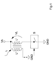
- reference number 1 indicates as a whole and diagrammatically a circuit provided in accordance with the present invention for detecting the presence of a spark produced by means of a spark coil L inserted in an electronic ignition device of an internal combustion motor.
- the coil L comprises a primary circuit L' inserted between a power supply voltage generator Vb and a controlled switch S and a secondary circuit L".
- the circuit 1 also comprises a first input block I provided e.g. by means of a resistive divider (R1,R2) having an input terminal connected to the primary circuit L' of the coil L and an output terminal.
- R1,R2 resistive divider
- This circuit comprises also a comparator C with hysteresis having a first input terminal connected to the output terminal of the input block I.
- the comparator also comprises a second and a third input terminals kept respectively at a first U1 and a second U2 reference voltage.
- this first reference voltage U1 and second reference voltage U2 represent respectively the upper and lower thresholds of the comparator C.
- the second reference voltage U2 is obtained preferably by means of a resistive divider (R3,R4) connected to the supply voltage generator Vb.
- the comparator C also comprises a low-pass filter FB.
- the circuit 1 also comprises a second signalling block SEG having an input terminal connected to an output terminal of the comparator C and an output terminal which is an output terminal OUT in the drawing of the circuit 1.
- This second signalling block SEG comprises in turn a counter CON having a first input terminal connected to the output terminal of the comparator C and a second input terminal receiving a timing signal Ck.
- the counter CON has an output connected to an input of a digital comparator CD having a second input terminal connected to a memory element M in which is memorized a binary reference value B.
- the comparator C with hysteresis compares this voltage U with the upper threshold U1 and lower threshold U2.
- a voltage Vc which is at a high logic level when the voltage U exceeds the threshold value U1.
- the voltage Vc by means of the filter FB keeps this logic level high for the entire duration of the transient until the voltage U falls below the lower threshold value U2 as shown in FIG. 4.
- the duration of the voltage Vc is proportional to the duration of the overvoltage created on the primary circuit L' of the coil L when the controlled switch S opens.
Landscapes
- Engineering & Computer Science (AREA)
- Chemical & Material Sciences (AREA)
- Combustion & Propulsion (AREA)
- Mechanical Engineering (AREA)
- General Engineering & Computer Science (AREA)
- Physics & Mathematics (AREA)
- General Physics & Mathematics (AREA)
- Ignition Installations For Internal Combustion Engines (AREA)
Claims (5)
- Verfahren zum Erfassen eines mittels einer Anregerspule (L) erzeugten Funkens, mit einem an einen Versorgungsstromgenerator (Vb) verbunden Primärkreis (L'), und einem Sekundärkreis (L"), wobei die Anregerspule (L) in einer elektronischen Zündvorrichtung eines Verbrennungsmotors eingesetzt ist, und wobei besagtes Verfahren dadurch gekennzeichnet ist, dass es folgende Schritte aufweist:Erzeugen eines ersten Spannungssignals (U), proportional zu einer im Primärkreis der Anregerspule (L) vorhandenen Spannung (VL);Vergleich zwischen dem ersten Spannungssignal (U) und einem ersten oberen Schwellwert (U1), und anschließendes Erzeugen eines zweiten Spannungssignals (Vc) mit einem ersten logischen Pegel, wenn der erste Spannungssignal den ersten oberen Schwellwert (U1) überschreitet;Aufrechthalten des besagten zweiten Spannungssignals (Vc) mit dem ersten logischen Pegel;Vergleich zwischen dem ersten Spannungssignal (U) und einem zweiten unteren Schwellwert (U2), proportional zur Versorgungsspannung (Vb), und anschließendes Erzeugen eines zweiten Spannungssignals (Vc) mit einem zweiten logischen Pegel, wenn der erste Spannungssignal den zweiten unteren Schwellwert (U2) unterschreitet;Erfassen der Zeitdauer des zweiten Spannungssignals (Vc); undMelden der Anwesenheit eines Funkens auf der sekundären Wicklung, falls besagte Zeitdauer einen Referenzwert (B) überschreitet.
- Verfahren nach Anspruch 1, dadurch gekennzeichnet dass der Schritt des Erfassen der Zeitdauer des zweiten Spannungssignals (Vc) folgenden Schritt beinhaltet:Erzeugen eines zur Zeitdauer des digitalen Spannungssignals (Vc) proportionalen Wertes (A).
- Verfahren nach Anspruch 2, dadurch gekennzeichnet dass der Schritt des Melden der Anwesenheit eines Funkens folgenden Schritt beinhaltet:Erzeugen eines Ausgangswertes (OUT), mit einem hohen logischen Pegel, wenn die Zeitdauer des zweiten Spannungssignals (Vc) einen Referenzwert (B) überschreitet.
- Verfahren nach Anspruch 1, dadurch gekennzeichnet dass der erste obere Schwellwert (U1) konstant ist.
- Verfahren nach Anspruch 1, dadurch gekennzeichnet dass der erste logische Pegel hoch und der zweite logische Pegel tief ist.
Priority Applications (3)
| Application Number | Priority Date | Filing Date | Title |
|---|---|---|---|
| EP95830169A EP0740072B1 (de) | 1995-04-28 | 1995-04-28 | Methode und Schaltung zur Erkennung eines Zündfunkens in einer inneren Brennkraftmaschine |
| DE69527702T DE69527702T2 (de) | 1995-04-28 | 1995-04-28 | Methode und Schaltung zur Erkennung eines Zündfunkens in einer inneren Brennkraftmaschine |
| US08/639,779 US5790039A (en) | 1995-04-28 | 1996-04-29 | Method for detecting the presence of a spark in an electronic ignition system used with an internal combustion engine |
Applications Claiming Priority (1)
| Application Number | Priority Date | Filing Date | Title |
|---|---|---|---|
| EP95830169A EP0740072B1 (de) | 1995-04-28 | 1995-04-28 | Methode und Schaltung zur Erkennung eines Zündfunkens in einer inneren Brennkraftmaschine |
Publications (2)
| Publication Number | Publication Date |
|---|---|
| EP0740072A1 EP0740072A1 (de) | 1996-10-30 |
| EP0740072B1 true EP0740072B1 (de) | 2002-08-07 |
Family
ID=8221908
Family Applications (1)
| Application Number | Title | Priority Date | Filing Date |
|---|---|---|---|
| EP95830169A Expired - Lifetime EP0740072B1 (de) | 1995-04-28 | 1995-04-28 | Methode und Schaltung zur Erkennung eines Zündfunkens in einer inneren Brennkraftmaschine |
Country Status (3)
| Country | Link |
|---|---|
| US (1) | US5790039A (de) |
| EP (1) | EP0740072B1 (de) |
| DE (1) | DE69527702T2 (de) |
Cited By (1)
| Publication number | Priority date | Publication date | Assignee | Title |
|---|---|---|---|---|
| TWI463144B (zh) * | 2012-08-17 | 2014-12-01 | Prolific Technology Inc | 可偵測突波訊號特性之突波偵測裝置 |
Families Citing this family (13)
| Publication number | Priority date | Publication date | Assignee | Title |
|---|---|---|---|---|
| JP3228159B2 (ja) | 1996-12-06 | 2001-11-12 | トヨタ自動車株式会社 | エンジンの点火プラグ検査方法 |
| EP1003967B1 (de) * | 1997-08-12 | 2005-02-16 | Siemens Aktiengesellschaft | Mess- und diagnoseeinrichtung für ein zündsystem einer brennkraftmaschine |
| US6278278B1 (en) | 1998-08-12 | 2001-08-21 | Siemens Aktiengesellschaft | Measuring and diagnostic device for an ignition system of an internal combustion engine |
| DE60015711T2 (de) * | 2000-01-27 | 2005-11-24 | Stmicroelectronics S.R.L., Agrate Brianza | Elektronische Zündungseinheit mit Beschränkung der Spannung an eine Anschluss der Zündungspulenprimärwicklung |
| US6492818B1 (en) * | 2000-11-06 | 2002-12-10 | Cummins, Inc. | Apparatus and method for determining component fault conditions as a function of primary coil voltage in a capacitive discharge ignition system |
| EP1403761B1 (de) * | 2001-06-27 | 2008-06-04 | Sony Corporation | Integrierte schaltungseinrichtung, informationsverarbeitungseinrichtung, informationsaufzeichnungseinrichtungsspeicher-verwaltungsverfahren, mobilendgeräteeinrichtung, integrierte halbleiterschaltungseinrichtung und kommunikationsverfahren mit tragbarem endgerät |
| DE102006054016A1 (de) * | 2006-11-16 | 2008-05-21 | Bayerische Motoren Werke Ag | Elektronische Überwachung des Bordnetzes eines Kraftfahrzeugs auf Spannungsspitzen oder Spannungseinbrüche |
| ITMI20130002A1 (it) * | 2013-01-03 | 2014-07-04 | St Microelectronics Srl | Apparato di controllo di una candela di accensione e sistema di accensione elettronica di motori con protezione da secondario aperto |
| CN103324226A (zh) * | 2013-06-28 | 2013-09-25 | 成都汉康信息产业有限公司 | 过压保护型遥测终端机 |
| JP5901718B1 (ja) * | 2014-09-24 | 2016-04-13 | 三菱電機株式会社 | 内燃機関制御装置 |
| EP3260778B1 (de) | 2016-06-21 | 2021-07-21 | John Zink Company, L.L.C. | System und verfahren zur detektion eines elektrischen funkens |
| CN106655084A (zh) * | 2016-10-25 | 2017-05-10 | 上海联影医疗科技有限公司 | 一种高压发生器打火保护装置及方法 |
| SE542389C2 (en) * | 2018-09-04 | 2020-04-21 | Sem Ab | An ignition system and method controlling spark ignited combustion engines |
Citations (1)
| Publication number | Priority date | Publication date | Assignee | Title |
|---|---|---|---|---|
| EP0654604A1 (de) * | 1993-11-22 | 1995-05-24 | Magneti Marelli France | Verfahren und Vorrichtung einer Spulenzündung mit zusätzlichen Entladungen zur Diagnose |
Family Cites Families (11)
| Publication number | Priority date | Publication date | Assignee | Title |
|---|---|---|---|---|
| US4377785A (en) * | 1979-07-06 | 1983-03-22 | Nippon Soken, Inc. | Device for diagnosing ignition system for use in internal combustion engine |
| IT1119341B (it) * | 1979-08-02 | 1986-03-10 | Cselt Centro Studi Lab Telecom | Analizzatore di tensioni impulsive |
| US4918389A (en) * | 1988-06-03 | 1990-04-17 | Robert Bosch Gmbh | Detecting misfiring in spark ignition engines |
| DE3907616A1 (de) * | 1989-03-09 | 1990-09-20 | Bosch Gmbh Robert | Schaltungsanordnung zur messung der primaerspannung einer zuendspule |
| US4913123A (en) * | 1989-03-23 | 1990-04-03 | Ford Motor Company | Ignition timing system with feedback correction |
| DE4009451C2 (de) * | 1989-03-27 | 1995-02-16 | Mitsubishi Electric Corp | Zündvorrichtung für eine Brennkraftmaschine |
| DE4020986C2 (de) * | 1990-07-02 | 1998-09-03 | Telefunken Microelectron | Elektronisches Zündsystem für eine Brennkraftmaschine |
| FR2676506B1 (fr) * | 1991-05-15 | 1993-09-03 | Siemens Automotive Sa | Procede et dispositif de detection de rates d'allumage dans un cylindre de moteur a combustion interne et leur application. |
| US5283527A (en) * | 1991-06-28 | 1994-02-01 | Ford Motor Company | Methods and apparatus for detecting short circuited secondary coil winding via monitoring primary coil winding |
| US5446385A (en) * | 1992-10-02 | 1995-08-29 | Robert Bosch Gmbh | Ignition system for internal combustion engines |
| US5534781A (en) * | 1994-08-15 | 1996-07-09 | Chrysler Corporation | Combustion detection via ionization current sensing for a "coil-on-plug" ignition system |
-
1995
- 1995-04-28 EP EP95830169A patent/EP0740072B1/de not_active Expired - Lifetime
- 1995-04-28 DE DE69527702T patent/DE69527702T2/de not_active Expired - Fee Related
-
1996
- 1996-04-29 US US08/639,779 patent/US5790039A/en not_active Expired - Lifetime
Patent Citations (1)
| Publication number | Priority date | Publication date | Assignee | Title |
|---|---|---|---|---|
| EP0654604A1 (de) * | 1993-11-22 | 1995-05-24 | Magneti Marelli France | Verfahren und Vorrichtung einer Spulenzündung mit zusätzlichen Entladungen zur Diagnose |
Cited By (1)
| Publication number | Priority date | Publication date | Assignee | Title |
|---|---|---|---|---|
| TWI463144B (zh) * | 2012-08-17 | 2014-12-01 | Prolific Technology Inc | 可偵測突波訊號特性之突波偵測裝置 |
Also Published As
| Publication number | Publication date |
|---|---|
| US5790039A (en) | 1998-08-04 |
| DE69527702D1 (de) | 2002-09-12 |
| DE69527702T2 (de) | 2002-12-05 |
| EP0740072A1 (de) | 1996-10-30 |
Similar Documents
| Publication | Publication Date | Title |
|---|---|---|
| EP0740072B1 (de) | Methode und Schaltung zur Erkennung eines Zündfunkens in einer inneren Brennkraftmaschine | |
| US7525783B2 (en) | Monitoring method for an actuator and corresponding driver circuit | |
| JPH088748B2 (ja) | 満充電検出回路 | |
| KR960020286A (ko) | 링트립 판정회로 | |
| US4478200A (en) | Electronic ignition system for internal combustion engine capable of supplying electric power to auxiliary unit | |
| EP0183223B1 (de) | Elektronische Zündanlage für Brennkraftmaschine | |
| US6367318B1 (en) | Multicharge ignition system having combustion feedback for termination | |
| KR100297673B1 (ko) | 점화제어시스템 | |
| KR930005158B1 (ko) | 내연기관의 노크 억제장치 | |
| EP0030816B1 (de) | Signalisieranordnungen für elektrische Wechselstromversorgung | |
| US4082075A (en) | Input quarter cycle timing circuit | |
| KR940001583B1 (ko) | 점화장치용 일시정지 제어신호 발생방법 및 일시정지 제어회로 | |
| US4204508A (en) | Ignition system for internal combustion engine | |
| US6948484B2 (en) | Capacitor discharge ignition device | |
| GB2180356A (en) | Ignition testing | |
| US4053823A (en) | Ignition arc monitor circuit | |
| JPH10176643A (ja) | コンデンサ充放電式点火装置 | |
| US4893085A (en) | Ignition monitoring circuit for an ignition system of an internal combustion engine including an erroneous pulse eliminating circuit means | |
| JP3582961B2 (ja) | 内燃機関のプレイグニッション検出装置 | |
| US4403592A (en) | Engine ignition system with automatic timing shift | |
| JP3283605B2 (ja) | イオン電流検出装置 | |
| EP0824704A2 (de) | Schaltung zur detektion des betrages oder der schwankung einer eingangsgleichspannung | |
| JP2848470B2 (ja) | 内燃機関用点火装置の故障検出装置 | |
| KR100700851B1 (ko) | 차량용 점화 고장 감지기 | |
| JPS62293941A (ja) | バツテリ−充電回路 |
Legal Events
| Date | Code | Title | Description |
|---|---|---|---|
| PUAI | Public reference made under article 153(3) epc to a published international application that has entered the european phase |
Free format text: ORIGINAL CODE: 0009012 |
|
| AK | Designated contracting states |
Kind code of ref document: A1 Designated state(s): DE FR GB IT |
|
| 17P | Request for examination filed |
Effective date: 19970421 |
|
| 17Q | First examination report despatched |
Effective date: 19970926 |
|
| RAP3 | Party data changed (applicant data changed or rights of an application transferred) |
Owner name: STMICROELECTRONICS S.R.L. |
|
| GRAG | Despatch of communication of intention to grant |
Free format text: ORIGINAL CODE: EPIDOS AGRA |
|
| RAP1 | Party data changed (applicant data changed or rights of an application transferred) |
Owner name: CHRYSLER CORPORATION Owner name: STMICROELECTRONICS S.R.L. |
|
| GRAG | Despatch of communication of intention to grant |
Free format text: ORIGINAL CODE: EPIDOS AGRA |
|
| GRAG | Despatch of communication of intention to grant |
Free format text: ORIGINAL CODE: EPIDOS AGRA |
|
| GRAH | Despatch of communication of intention to grant a patent |
Free format text: ORIGINAL CODE: EPIDOS IGRA |
|
| GRAH | Despatch of communication of intention to grant a patent |
Free format text: ORIGINAL CODE: EPIDOS IGRA |
|
| GRAA | (expected) grant |
Free format text: ORIGINAL CODE: 0009210 |
|
| RAP1 | Party data changed (applicant data changed or rights of an application transferred) |
Owner name: DAIMLERCHRYSLER CORPORATION Owner name: STMICROELECTRONICS S.R.L. |
|
| AK | Designated contracting states |
Kind code of ref document: B1 Designated state(s): DE FR GB IT |
|
| REG | Reference to a national code |
Ref country code: GB Ref legal event code: FG4D |
|
| REF | Corresponds to: |
Ref document number: 69527702 Country of ref document: DE Date of ref document: 20020912 |
|
| ET | Fr: translation filed | ||
| PLBE | No opposition filed within time limit |
Free format text: ORIGINAL CODE: 0009261 |
|
| STAA | Information on the status of an ep patent application or granted ep patent |
Free format text: STATUS: NO OPPOSITION FILED WITHIN TIME LIMIT |
|
| 26N | No opposition filed |
Effective date: 20030508 |
|
| PGFP | Annual fee paid to national office [announced via postgrant information from national office to epo] |
Ref country code: DE Payment date: 20040329 Year of fee payment: 10 |
|
| PG25 | Lapsed in a contracting state [announced via postgrant information from national office to epo] |
Ref country code: IT Free format text: LAPSE BECAUSE OF NON-PAYMENT OF DUE FEES;WARNING: LAPSES OF ITALIAN PATENTS WITH EFFECTIVE DATE BEFORE 2007 MAY HAVE OCCURRED AT ANY TIME BEFORE 2007. THE CORRECT EFFECTIVE DATE MAY BE DIFFERENT FROM THE ONE RECORDED. Effective date: 20050428 |
|
| PG25 | Lapsed in a contracting state [announced via postgrant information from national office to epo] |
Ref country code: DE Free format text: LAPSE BECAUSE OF NON-PAYMENT OF DUE FEES Effective date: 20051101 |
|
| PGFP | Annual fee paid to national office [announced via postgrant information from national office to epo] |
Ref country code: GB Payment date: 20060327 Year of fee payment: 12 |
|
| GBPC | Gb: european patent ceased through non-payment of renewal fee |
Effective date: 20070428 |
|
| PG25 | Lapsed in a contracting state [announced via postgrant information from national office to epo] |
Ref country code: GB Free format text: LAPSE BECAUSE OF NON-PAYMENT OF DUE FEES Effective date: 20070428 |
|
| PGFP | Annual fee paid to national office [announced via postgrant information from national office to epo] |
Ref country code: FR Payment date: 20070426 Year of fee payment: 13 |
|
| REG | Reference to a national code |
Ref country code: FR Ref legal event code: ST Effective date: 20081231 |
|
| REG | Reference to a national code |
Ref country code: FR Ref legal event code: CD |
|
| PG25 | Lapsed in a contracting state [announced via postgrant information from national office to epo] |
Ref country code: FR Free format text: LAPSE BECAUSE OF NON-PAYMENT OF DUE FEES Effective date: 20080430 |