EP0740099A1 - Dispositif d'ajustage - Google Patents
Dispositif d'ajustage Download PDFInfo
- Publication number
- EP0740099A1 EP0740099A1 EP96106771A EP96106771A EP0740099A1 EP 0740099 A1 EP0740099 A1 EP 0740099A1 EP 96106771 A EP96106771 A EP 96106771A EP 96106771 A EP96106771 A EP 96106771A EP 0740099 A1 EP0740099 A1 EP 0740099A1
- Authority
- EP
- European Patent Office
- Prior art keywords
- expansion element
- adjusting device
- tubular
- installation device
- flanges
- Prior art date
- Legal status (The legal status is an assumption and is not a legal conclusion. Google has not performed a legal analysis and makes no representation as to the accuracy of the status listed.)
- Withdrawn
Links
- 239000000463 material Substances 0.000 claims abstract description 3
- 238000009434 installation Methods 0.000 claims description 46
- CURLTUGMZLYLDI-UHFFFAOYSA-N Carbon dioxide Chemical compound O=C=O CURLTUGMZLYLDI-UHFFFAOYSA-N 0.000 description 4
- 229910002092 carbon dioxide Inorganic materials 0.000 description 2
- 239000001569 carbon dioxide Substances 0.000 description 2
- 230000007613 environmental effect Effects 0.000 description 2
- 230000006978 adaptation Effects 0.000 description 1
- 230000001419 dependent effect Effects 0.000 description 1
- 239000007788 liquid Substances 0.000 description 1
- 238000000034 method Methods 0.000 description 1
- 230000002787 reinforcement Effects 0.000 description 1
- XLYOFNOQVPJJNP-UHFFFAOYSA-N water Substances O XLYOFNOQVPJJNP-UHFFFAOYSA-N 0.000 description 1
- 238000004804 winding Methods 0.000 description 1
Images



Classifications
-
- F—MECHANICAL ENGINEERING; LIGHTING; HEATING; WEAPONS; BLASTING
- F16—ENGINEERING ELEMENTS AND UNITS; GENERAL MEASURES FOR PRODUCING AND MAINTAINING EFFECTIVE FUNCTIONING OF MACHINES OR INSTALLATIONS; THERMAL INSULATION IN GENERAL
- F16L—PIPES; JOINTS OR FITTINGS FOR PIPES; SUPPORTS FOR PIPES, CABLES OR PROTECTIVE TUBING; MEANS FOR THERMAL INSULATION IN GENERAL
- F16L23/00—Flanged joints
- F16L23/003—Auxiliary devices
-
- F—MECHANICAL ENGINEERING; LIGHTING; HEATING; WEAPONS; BLASTING
- F16—ENGINEERING ELEMENTS AND UNITS; GENERAL MEASURES FOR PRODUCING AND MAINTAINING EFFECTIVE FUNCTIONING OF MACHINES OR INSTALLATIONS; THERMAL INSULATION IN GENERAL
- F16L—PIPES; JOINTS OR FITTINGS FOR PIPES; SUPPORTS FOR PIPES, CABLES OR PROTECTIVE TUBING; MEANS FOR THERMAL INSULATION IN GENERAL
- F16L23/00—Flanged joints
- F16L23/006—Attachments
Definitions
- the invention relates to an adjusting device for adjusting an installation device between two flanges of a pipeline system, the two flanges being connectable via preferably bolt-shaped connecting means.
- Installation devices for use in a piping system for example measuring devices for measuring process parameters, such as volume flow meters, and accessories, are basically designed for mounting between two flanges of the piping system.
- these flanges correspond to different standards for different piping systems, such as DIN, ANSI and JIS.
- flangeless devices are nowadays increasingly used which can be clamped between the flanges of two sections of the piping system.
- the flanges are connected by connecting means which run in the longitudinal direction of the mounting device.
- bolts are used as connecting means, which, however, can have different bolt diameters depending on the application and the standard used.
- the adjustment is carried out by means of two rings with eccentrics, which are arranged around the casing of an installation device to be mounted.
- the rings By turning the rings, the preferably bolt-shaped connecting means are pressed outwards against the edge of the flange bores for the connecting means, the installation device being adjusted relative to the pipeline system at the same time.
- the known adjustment devices are problematic from various points of view. Initially, the known adjustment devices can only be used once. After the installation of the installation device in the pipeline system, the known adjustment devices are caught within the connecting means. Since the known adjustment devices are thus connected to the installation device over the entire service life, they, like the installation devices, may have to be resistant to extreme environmental conditions, such as high or low temperatures, which causes additional costs. Furthermore, it is necessary in the known adjusting devices that they are both adapted to the type of flange used and that they are adapted to the diameter of the mounting device. The use of the known adjustment devices for installation devices with an irregularly shaped jacket is not possible or only possible under special conditions. Finally, the casing of the installation device is not infrequently damaged when using the known adjusting devices.
- the present invention is therefore based on the object of providing an easy-to-use, flexible and inexpensive adjusting device.
- the adjusting device consists essentially of an expansion element which can be expanded by the inflow of a medium, and in that the expansion element lies in the expanded state on the installation device and the connecting elements.
- the adjusting device according to the invention is inserted over the largest possible area between the installation device and the surrounding preferably bolt-shaped connecting means.
- an inflowing medium such as a gas or a liquid
- the essentially tubular installation device between the connecting means is adjusted with sufficient pressure of the inflowing medium in such a way that the axis of the installation device is coaxial with the axis of the piping system.
- the installation device After the installation device has been adjusted in this way, it can, if necessary, be brought into a suitable installation position by rotating it about its axis. Then the connecting means of the two flanges are tightened and thus the installation device between the two flanges of the piping system. After the installation device has been clamped in, the medium is allowed to flow out of the expansion element and, after the expansion element has slackened, it can be removed from the space between the installation device and the connecting means.
- the adjusting device according to the invention therefore does not remain on the mounting device and is therefore reusable or does not have to be adapted to extreme environmental conditions during operation of the mounting device, while on the other hand it ensures and goes a much more flexible adaptation to the flange types or connecting means and mounting devices used in addition, particularly gently with the jacket of the mounting device.
- the adjustment device according to the invention can also be produced much more cost-effectively.
- the adjusting device according to the invention experiences a first advantageous embodiment in that the expansion element consists of a material that is as inelastic as possible. This additional measure ensures that relatively large forces build up between the installation device and the connecting means, since the pressure built up cannot ineffectively dissipate via expansion of the expansion element at locations where it is not in contact with the installation device or the connecting means.
- the adjustment device according to the invention is particularly easy to handle in that the expansion element is essentially cuff-shaped. Such a configuration of the expansion element ensures that it can be placed around the respective installation device in one movement.
- the adjusting device according to the invention is particularly flexible in that the expansion element is essentially tubular and that the length of the tubular expansion element is at least a multiple of the circumference of the mounting device. This measure ensures that the expansion element almost in connection with all conceivable Mounting devices can be used in that it is wrapped around the mounting device at regular intervals.
- tubular expansion element is used several times in connection with a specific installation device, it is advantageous to connect the tubular expansion element with a sleeve. This ensures particularly simple handling of the adjusting device according to the invention.
- the simplest and least expensive version of the tubular expansion element is that it is firmly closed at its first end.
- the tubular expansion element can be designed such that it can be closed at any point.
- the tubular expansion element is advantageously closed at any point by a clamping device.
- the closure at any point on the expansion element has the advantage that the medium flowing into the tubular expansion element does not flow unused into a section of the tubular expansion element that is no longer required for adjustment.
- a tubular expansion element has a particularly advantageous embodiment in that the medium flows into the tubular expansion element from a second end. There is therefore no need to provide separate access to the expansion element.
- the adjustment device according to the invention is particularly advantageous in that the gas of a high-pressure cartridge can be used as the medium. This ensures a particularly simple, location-independent handling of the adjustment device.
- the connection of the expansion element to existing high-pressure air systems or water pipes is also conceivable.
- FIG. 1 of the drawing shows an exemplary embodiment of an adjusting device according to the invention for adjusting an essentially tubular installation device 1 between two flanges 2, 3 of a pipeline system 4, the two flanges 2, 3 being connected via bolt-shaped connecting means 5.
- the bolt-shaped connecting means 5 are provided with attached nuts 6 at their ends.
- FIG. 1 The exemplary embodiment of an adjusting device 1 according to the invention shown in FIG. 1 essentially consists of a tubular expansion element 7 that can be expanded by the inflow of a medium.
- the tubular expansion element 7 is shown in the unexpanded state.
- the tubular expansion element 7 is shown wrapped around the installation device 1 at regular intervals. The winding of the tubular expansion element 7 over the entire length of the installation device 1 ensures a uniform adjustment of the installation device 1 over the entire length.
- a common high-pressure cartridge 8 filled with carbon dioxide is shown in FIG. 1 as the source of the medium which provides for the expansion of the tubular expansion element 7.
- This high-pressure cartridge 8 is inserted into the holder 9, also shown, and opened by screwing the holder 9.
- FIG. 2 shows the exemplary embodiment of an adjusting device according to the invention shown in FIG. 1, cut along the line II-II shown in FIG. 1.
- the tubular expansion element 7, as in FIG. 1 is shown in the unexpanded state.
- the axes of the installation device 1 and the piping system 4 are not coaxial, but are at a distance ⁇ C from one another.
- the bolt-shaped connecting means 5 are each due to their weight on the lower sides of flange bores 10 in the flanges 2, 3.
- the tubular expansion element 7 is firmly closed at its first end 11.
- Fig. 3 shows the embodiment of an adjusting device according to the invention in the expanded state in the section already shown in Fig. 2.
- the axes of the installation device 1 and the piping system 4 are now coaxial in the expanded state of the expansion element 7.
- the bolt-shaped connecting means 5 are pressed radially outward against the flange bores 10 by the forces that occur. It is now readily understood that this adjustment is independent of the one chosen Execution of the flange and possibly varying diameter of the bolt-shaped connecting means 5 succeed.
- FIG. 1 shows the state shown in FIG.
- the bolt-shaped connecting means 5 are now tightened and thus the installation device 1 is fastened between the flanges 2, 3.
- the holder 9 can be opened, as a result of which the carbon dioxide gas located in the tubular expansion element 7 flows out and the tubular expansion element 7 is thus released.
- a commercially available garden hose with cross-braided reinforcement is excellently suitable for the tubular expansion element 7.
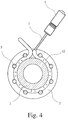
- FIG. 4 shows an embodiment of the adjusting device according to the invention, in which the expansion element 7 is connected to a sleeve 12; the tubular expansion element 7 is, as it were, integrated into the sleeve 12.
- FIG. 6, shows that the expansion element 7 is arranged in a meandering manner in the sleeve 12.
- the sleeve 12 with the integrated expansion element 7 is therefore placed between the installation device 1 and the connecting element 5. This can be simpler than the wrapping of the installation device 1 with the tubular expansion element 7 necessary for the exemplary embodiment according to FIGS. 1 to 3.
Landscapes
- Engineering & Computer Science (AREA)
- General Engineering & Computer Science (AREA)
- Mechanical Engineering (AREA)
- Supports For Pipes And Cables (AREA)
- Joints Allowing Movement (AREA)
- Pipe Accessories (AREA)
Applications Claiming Priority (2)
| Application Number | Priority Date | Filing Date | Title |
|---|---|---|---|
| DE19515237A DE19515237C2 (de) | 1995-04-29 | 1995-04-29 | Justiervorrichtung |
| DE19515237 | 1995-04-29 |
Publications (1)
| Publication Number | Publication Date |
|---|---|
| EP0740099A1 true EP0740099A1 (fr) | 1996-10-30 |
Family
ID=7760350
Family Applications (1)
| Application Number | Title | Priority Date | Filing Date |
|---|---|---|---|
| EP96106771A Withdrawn EP0740099A1 (fr) | 1995-04-29 | 1996-04-29 | Dispositif d'ajustage |
Country Status (5)
| Country | Link |
|---|---|
| US (1) | US5758903A (fr) |
| EP (1) | EP0740099A1 (fr) |
| JP (1) | JPH08303675A (fr) |
| CN (1) | CN1138674A (fr) |
| DE (1) | DE19515237C2 (fr) |
Families Citing this family (6)
| Publication number | Priority date | Publication date | Assignee | Title |
|---|---|---|---|---|
| DE29714082U1 (de) * | 1997-08-07 | 1997-10-02 | Feodor Burgmann Dichtungswerke GmbH & Co, 82515 Wolfratshausen | Montageanordnung mit Sicherungsring |
| US7703745B2 (en) * | 2006-04-25 | 2010-04-27 | Fisher Controls International Llc | Seal retainer/longitudinal centering clips with multiple flange capability |
| CN101251376B (zh) * | 2008-03-20 | 2010-04-21 | 上海交通大学 | 圆柱体环抱周向扫查机构 |
| PL2829781T3 (pl) * | 2013-07-22 | 2015-12-31 | Hauff Technik Gmbh & Co Kg | Korpus dociskowy dla uszczelki dociskowej i uszczelka dociskowa |
| PL3290765T3 (pl) | 2016-08-30 | 2020-07-13 | Hauff-Technik Gmbh & Co. Kg | Ściskana uszczelka z naciskowym korpusem |
| CN112207156A (zh) * | 2020-11-11 | 2021-01-12 | 湖南金海钢结构有限公司 | 一种钢管管径校圆装置及校圆方法 |
Citations (3)
| Publication number | Priority date | Publication date | Assignee | Title |
|---|---|---|---|---|
| FR1598405A (fr) * | 1968-12-11 | 1970-07-06 | ||
| US3643983A (en) * | 1969-11-21 | 1972-02-22 | Andrews Ind | Devices for axial alignment of pipe or other flanges |
| DE2160199B2 (de) * | 1971-12-04 | 1974-01-24 | Gustav F. Gerdts Kg, 2800 Bremen | Zentrierring für flanschlose Armaturen |
Family Cites Families (17)
| Publication number | Priority date | Publication date | Assignee | Title |
|---|---|---|---|---|
| DE1074336B (de) * | 1960-01-28 | Siemens & Halske Aktiengesellschaft, Berlin und München | Verfahren zum Verbinden von Rohren mit genauer Innenzentrierung, insbesondere von Hohlleiterrohren für die Übertragung von Hoi-Wellen | |
| US2517391A (en) * | 1947-03-06 | 1950-08-01 | Smith Corp A O | Joint coupling |
| DE850671C (de) * | 1949-08-04 | 1952-09-25 | Siemens Ag | Einbauanordnung fuer Zaehlwerke, insbesondere von Fluessigkeitsmessern |
| US3082022A (en) * | 1958-11-03 | 1963-03-19 | James A Moore | Coupling for plastic pipe having segmented interlocked clamping rings |
| GB1019691A (en) * | 1964-02-25 | 1966-02-09 | Ass Elect Ind | Improvements in or relating to the clamping together of coaxial pipes |
| US3406986A (en) * | 1967-06-16 | 1968-10-22 | Phillips Petroleum Co | Conduit coupling |
| DE2214636A1 (de) * | 1972-03-25 | 1973-10-04 | Guenter Perske | Verfahren und vorrichtung zum ausrichten von rohren |
| US3830527A (en) * | 1972-08-04 | 1974-08-20 | Phillips Petroleum Co | Aligning apparatus |
| US3875969A (en) * | 1973-01-31 | 1975-04-08 | Foxboro Co | Alignment sleeves for flangeless flowmeters and the like |
| US3876337A (en) * | 1973-03-15 | 1975-04-08 | Varian Associates | High vacuum pumping systems |
| US4872709A (en) * | 1983-05-02 | 1989-10-10 | The Dow Chemical Company | Pipe aligning apparatus |
| DE3340465C2 (de) * | 1983-11-09 | 1986-07-03 | Deutsche Gesellschaft für Wiederaufarbeitung von Kernbrennstoffen mbH, 3000 Hannover | Rohrleitungsverbindungsvorrichtung zum Verbinden von ortsfesten Rohrleitungsanschlüssen |
| DE3341044A1 (de) * | 1983-11-12 | 1985-05-30 | Deutsche Gesellschaft für Wiederaufarbeitung von Kernbrennstoffen mbH, 3000 Hannover | Zentriervorrichtung fuer zusammenkuppelbare rohrleitungsteile |
| US4637641A (en) * | 1985-06-05 | 1987-01-20 | Kennedy Jr Harold | Assembly means for standardized mechanical joint for pipeline appurtenances |
| FR2615267B1 (fr) * | 1987-05-13 | 1989-09-22 | Bibollet Bruno | Outil destine a l'emboitement de canalisations |
| GB8814368D0 (en) * | 1988-06-16 | 1988-07-20 | Hunting Oilfield Services Ltd | Improvements in & relating to method & apparatus for carrying out sub-sea operations lines |
| DE3830367A1 (de) * | 1988-09-07 | 1990-03-15 | Metallgesellschaft Ag | Einrichtung zur fernmontage eines einbauteils |
-
1995
- 1995-04-29 DE DE19515237A patent/DE19515237C2/de not_active Expired - Fee Related
-
1996
- 1996-04-26 US US08/639,867 patent/US5758903A/en not_active Expired - Fee Related
- 1996-04-29 EP EP96106771A patent/EP0740099A1/fr not_active Withdrawn
- 1996-04-29 CN CN96107377A patent/CN1138674A/zh active Pending
- 1996-04-30 JP JP8108893A patent/JPH08303675A/ja active Pending
Patent Citations (3)
| Publication number | Priority date | Publication date | Assignee | Title |
|---|---|---|---|---|
| FR1598405A (fr) * | 1968-12-11 | 1970-07-06 | ||
| US3643983A (en) * | 1969-11-21 | 1972-02-22 | Andrews Ind | Devices for axial alignment of pipe or other flanges |
| DE2160199B2 (de) * | 1971-12-04 | 1974-01-24 | Gustav F. Gerdts Kg, 2800 Bremen | Zentrierring für flanschlose Armaturen |
Also Published As
| Publication number | Publication date |
|---|---|
| US5758903A (en) | 1998-06-02 |
| JPH08303675A (ja) | 1996-11-22 |
| DE19515237C2 (de) | 1997-04-24 |
| DE19515237A1 (de) | 1996-10-31 |
| CN1138674A (zh) | 1996-12-25 |
Similar Documents
| Publication | Publication Date | Title |
|---|---|---|
| DE102009052674B4 (de) | Verfahren und Vorrichtung zum Verbinden von Doppelmantelrohren | |
| EP0550813A1 (fr) | Raccord de tuyaux | |
| DE2832614A1 (de) | Verbindungsstueck fuer rohrleitungen | |
| DE3443943A1 (de) | Rohrverbindung | |
| DE102021115904A1 (de) | Flanschverbindungsanordnung für eine rohrleitung | |
| DE2922403A1 (de) | Rohrverbindungsstueck | |
| DE19515237C2 (de) | Justiervorrichtung | |
| EP0899493A1 (fr) | Traversée de câble/tuyaux pour une ouverture dans un mur | |
| EP3967888A1 (fr) | Dispositif de fixation | |
| DE102019002736B4 (de) | Wärmetauschersystem mit einer Manschette zum Verbinden von Leitungen eines Wärmetauschermoduls | |
| DE2002826A1 (de) | Kupplungsstueck fuer Roehren oder Schlaeuche | |
| DE4123383C2 (de) | Anordnung mit einer Elektro-Schweißmuffe | |
| DE19910522C1 (de) | Rohrinnenmuffe mit Manschette und Packer sowie Verfahren zur Innenabdichtung von Rohrleitungen | |
| EP0959291A2 (fr) | Raccord de tuyau | |
| EP3885588B1 (fr) | Manchon isolant | |
| AT401095B (de) | Anschluss eines gerätes an eine rohrförmige armatur | |
| DE29600241U1 (de) | Lösbare Rohrverbindung für Kunststoffrohre | |
| DE7035177U (de) | Schutzvorrichtung fuer leitungen. | |
| DE102019110305B4 (de) | Hausanschlussbuchse und Hausanschlussanordnung | |
| EP0340338B1 (fr) | Raccord de tuyau | |
| DE19852582C2 (de) | Elastisches Absperrelement zum abdichtenden Absperren eines Ringspaltes zwischen wenigstens einer Medienleitung und einer diese umgebenden Wandung, beispielsweise einem Schutzrohr | |
| EP1174234A2 (fr) | Méthode et dispositif pour revêtir la paroi intérieure de tuyaux | |
| DE102024100232A1 (de) | Anschlussset für Wärme- und/oder Kälteerzeuger, insbesondere Wärmepumpen, sowie Mehrfachrohrsystem | |
| DE9103870U1 (de) | Vorrichtung zum Prüfen von Rohrleitungen | |
| DE9310712U1 (de) | Rohrverbindung |
Legal Events
| Date | Code | Title | Description |
|---|---|---|---|
| PUAI | Public reference made under article 153(3) epc to a published international application that has entered the european phase |
Free format text: ORIGINAL CODE: 0009012 |
|
| AK | Designated contracting states |
Kind code of ref document: A1 Designated state(s): CH DE FR GB LI NL |
|
| 17P | Request for examination filed |
Effective date: 19970104 |
|
| 17Q | First examination report despatched |
Effective date: 19981120 |
|
| STAA | Information on the status of an ep patent application or granted ep patent |
Free format text: STATUS: THE APPLICATION IS DEEMED TO BE WITHDRAWN |
|
| 18D | Application deemed to be withdrawn |
Effective date: 19990601 |