EP0740159A1 - Système de mesure pour décharges partielles - Google Patents
Système de mesure pour décharges partielles Download PDFInfo
- Publication number
- EP0740159A1 EP0740159A1 EP95201031A EP95201031A EP0740159A1 EP 0740159 A1 EP0740159 A1 EP 0740159A1 EP 95201031 A EP95201031 A EP 95201031A EP 95201031 A EP95201031 A EP 95201031A EP 0740159 A1 EP0740159 A1 EP 0740159A1
- Authority
- EP
- European Patent Office
- Prior art keywords
- mhz
- signal
- voltage
- interruption
- cable
- Prior art date
- Legal status (The legal status is an assumption and is not a legal conclusion. Google has not performed a legal analysis and makes no representation as to the accuracy of the status listed.)
- Withdrawn
Links
Images

Classifications
-
- G—PHYSICS
- G01—MEASURING; TESTING
- G01R—MEASURING ELECTRIC VARIABLES; MEASURING MAGNETIC VARIABLES
- G01R31/00—Arrangements for testing electric properties; Arrangements for locating electric faults; Arrangements for electrical testing characterised by what is being tested not provided for elsewhere
- G01R31/12—Testing dielectric strength or breakdown voltage ; Testing or monitoring effectiveness or level of insulation, e.g. of a cable or of an apparatus, for example using partial discharge measurements; Electrostatic testing
- G01R31/1227—Testing dielectric strength or breakdown voltage ; Testing or monitoring effectiveness or level of insulation, e.g. of a cable or of an apparatus, for example using partial discharge measurements; Electrostatic testing of components, parts or materials
- G01R31/1263—Testing dielectric strength or breakdown voltage ; Testing or monitoring effectiveness or level of insulation, e.g. of a cable or of an apparatus, for example using partial discharge measurements; Electrostatic testing of components, parts or materials of solid or fluid materials, e.g. insulation films, bulk material; of semiconductors or LV electronic components or parts; of cable, line or wire insulation
- G01R31/1272—Testing dielectric strength or breakdown voltage ; Testing or monitoring effectiveness or level of insulation, e.g. of a cable or of an apparatus, for example using partial discharge measurements; Electrostatic testing of components, parts or materials of solid or fluid materials, e.g. insulation films, bulk material; of semiconductors or LV electronic components or parts; of cable, line or wire insulation of cable, line or wire insulation, e.g. using partial discharge measurements
Definitions
- the present invention relates to a method and a device for measuring partial discharges in cables and fittings.
- Partial discharges are discharges which occur in the dielectric located between the inner conductor and the earth shield of a high-voltage cable, wherein complete breakdown does not take place.
- Partial discharges are also often the initiator of complete discharges (breakdown).
- Partial discharges occur inter alia in cables provided with a dielectric manufactured from plastic. With the increasing use of such cables it is important to have available a measuring method with which such partial discharges can be detected, also in the case of already installed cables.
- This method is however only applicable in cables provided with an earth shield, wherein a conductor incorporated in the earth shield extends helically.
- the present invention relates to a method and device applicable with such cables. In order to be able to determine the occurrence of partial discharges in the case of such a solid metal shield it is necessary to interrupt the metal earth shield.
- the quality of the partial discharge can be determined. Understood for instance by displaying is making an image on the screen of an oscilloscope, making a print-out by means of an oscillograph, or possible storing of an image in a memory in digital form. Examination of an image can provide information relating to the seriousness and the nature of the partial discharge.
- a method for determining the quality of partial discharges in the insulation of cables comprising the following steps of: interrupting the metal earth shield of the cable; connecting both sides of the interrupted sheath to a measuring instrument; arranging a connection between both sides of the interrupted sheath which is at least suitable for transferring signals with the mains frequency; and displaying the signal.
- the object of the present invention is to avoid the above stated problems.
- This object is achieved in that only signal components with frequencies greater than 0.5 MHz are displayed.
- cut-off frequency 0.5 MHz it is possible to select other cut-off frequencies, for instance 1 MHz, 2 MHz, 5 MHz, 10 MHz or intermediate cut-off frequencies.
- Another interesting aspect of the said frequency range lies in the fact that although a partial discharge generates phenomena which extend over a frequency range of about 100 Hz to several hundred MHz, the distance over which the relevant signals are transmitted is highly frequency-dependent. Signals with a low frequency generally travel over a great distance, while signals with higher frequencies travel over shorter distances as a result of damping and dispersion.
- the method according to the present invention provides such a method.
- the signal for displaying is preferably limited in frequency by short-circuiting the interruption of the earth shield.
- a device for determining the quality of a partial discharge occurring in the cable comprising: means for deflecting a measuring voltage occurring over an interruption of the earth shield; and an instrument for displaying the measuring voltage, characterized in that the deflecting means are formed by an interruption of the sheath of the cable, wherein both sides of the interruption are connected to the measuring instrument and the interruption of the earth shield is short-circuited by a connection suitable for allowing passage of signals with a frequency smaller than 0.5 MHz.
- the present invention provides a method wherein prior to display the signal is combined with a signal representing the mains voltage.
- Such a method is applicable for single-phase systems such as occur in power supply systems of rail networks supplied with alternating current.
- the signal representing the mains voltage is generated by at least two, preferably three, electrodes each of which is coupled capacitively to a conductor carrying the relevant phase voltage.
- a cable 1 with a coaxial structure which cable is formed by a central conductor 2 and a sheath conductor 3, between which is arranged a dielectric 4.
- plastic insulation material 42 is present around the sheath conductor 3.
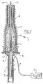
- FIG. 1 A similar situation is shown in figure 2. Shown herein is an end fitting 11 to which is connected an underground cable 12. Such a situation occurs for instance at the transition between an underground cable and a high-voltage line.
- the high-voltage line 13 is herein connected to the top of the end fitting 11.
- the underground cable is provided with a central conductor 2 and a sheath conductor 3, between which is arranged the dielectric 4.
- semi-conductor voltage-controlling layers 14 which are however of no significance for the present invention and which are not further discussed.
- the end fitting 11 rests on a conducting plate 15, while end fitting 11 is formed by an insulating mass 16, a reinforcing housing 17, on the outside of which is arranged a housing 18 also manufactured from insulating material. The construction of the end fitting is not otherwise important and is not discussed further.
- the sheath 3 of underground cable 12 is connected to the conducting plate 15 by means of a connecting cable 20 usually made of Litz.
- a connecting cable 20 usually made of Litz.
- the sheath 3 can be connected directly to the conducting plate 15. In that case an interruption of sheath 3 will have to be realized.
- the high-frequency signals that is, with a frequency higher than 0.5 MHz, do not cross over such an interruption. It is thus possible to connect the measuring wire 8 over this interruption by means of the cores 9 and 10.
- the measurement signal is hereby supplied to the measuring instrument 21.
- the instrument 21 is formed by a display device which can be formed by an oscilloscope, and an oscillograph with which it is possible to obtain oscillograms of the voltage phenomenon, or by a digital instrument with which the result of the measurement can be stored in digital form and subsequently printed out in processed form and made visible.
- connection with a filtering action for instance the short-circuit connection, with which frequencies lower than 0.5, 1, 2, 5 or 10 MHz are largely suppressed.
- the displayed image is hereby limited to only the signal components whose frequency is higher than the cut-off frequency and which can only travel a short distance along the cable sheath, but wherein such signals are only to a small extent sensitive to, or, as the case may be, influenced by, noise, broadcasting signals and other interference signals.
- FIG. 3 Shown herein is a three-phase system which is formed by three conductors R, S and T which carry a three-phase voltage system.
- the three conductors R, S and T are situated above a conductor 22 with earth potential formed for instance by the earth surface, above which three electrodes 23,24 and 25 are disposed in insulated manner.
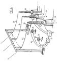
- figure 4 shows a schematic view of a measuring arrangement.
- end fittings 27,28 and 29 Arranged herein on a conducting surface 26 are end fittings 27,28 and 29 to each of which is connected an underground cable 30,31 and 32 respectively.
- To the top side of each of the connections are connected respective high-voltage lines 33,34 and 35.
- the high-voltage lines are herein suspended from a portal 36 by means of insulators 37.
- the voltages occurring over the interruptions on the underside of the end fittings 27,28 and 29 are fed by means of three measuring cables 8 to the measuring instrument 21. This means that there is a three-fold measurement here; it is of course equally possible to make use of a single measurement or a double measurement.
- each of the electrodes is connected by means of cables 40 to a matrix circuit 41, which matrix circuit calculates the voltage prevailing on the lines 33,34 and 35 from the voltages occurring on the electrodes 23,24,25 and supplies the desired phase voltage to the measuring instrument 21.
- the method of combining the measurement signal with the mains voltage is not limited to the method for obtaining the measurement signal described in the present application; it can also be applied in for instance the method according to the Netherlands patent application number 92.01944.
Landscapes
- Physics & Mathematics (AREA)
- General Physics & Mathematics (AREA)
- Testing Relating To Insulation (AREA)
Priority Applications (5)
| Application Number | Priority Date | Filing Date | Title |
|---|---|---|---|
| EP95201031A EP0740159A1 (fr) | 1995-04-21 | 1995-04-21 | Système de mesure pour décharges partielles |
| AU50687/96A AU714368B2 (en) | 1995-04-21 | 1996-04-15 | Measuring system for partial discharges |
| US08/634,308 US5854556A (en) | 1995-04-21 | 1996-04-16 | Measurement system for partial discharges on dielectrics in coaxial cables |
| CA002174606A CA2174606A1 (fr) | 1995-04-21 | 1996-04-19 | Systeme de mesure de decharges partielles |
| JP8098097A JPH095387A (ja) | 1995-04-21 | 1996-04-19 | 部分放電の測定システム |
Applications Claiming Priority (1)
| Application Number | Priority Date | Filing Date | Title |
|---|---|---|---|
| EP95201031A EP0740159A1 (fr) | 1995-04-21 | 1995-04-21 | Système de mesure pour décharges partielles |
Publications (1)
| Publication Number | Publication Date |
|---|---|
| EP0740159A1 true EP0740159A1 (fr) | 1996-10-30 |
Family
ID=8220216
Family Applications (1)
| Application Number | Title | Priority Date | Filing Date |
|---|---|---|---|
| EP95201031A Withdrawn EP0740159A1 (fr) | 1995-04-21 | 1995-04-21 | Système de mesure pour décharges partielles |
Country Status (5)
| Country | Link |
|---|---|
| US (1) | US5854556A (fr) |
| EP (1) | EP0740159A1 (fr) |
| JP (1) | JPH095387A (fr) |
| AU (1) | AU714368B2 (fr) |
| CA (1) | CA2174606A1 (fr) |
Cited By (4)
| Publication number | Priority date | Publication date | Assignee | Title |
|---|---|---|---|---|
| GB2388723A (en) * | 2002-05-03 | 2003-11-19 | Gen Electric | Monitoring wiring systems of aircraft |
| CN102914730A (zh) * | 2012-10-16 | 2013-02-06 | 中国电力科学研究院 | 光纤复合架空相线接头盒干耐受电压试验装置及试验方法 |
| CN104849628A (zh) * | 2015-04-24 | 2015-08-19 | 国网四川省电力公司电力科学研究院 | 一种电缆附件故障分析检测方法 |
| CN102928746B (zh) * | 2012-10-16 | 2016-04-20 | 中国电力科学研究院 | 光纤复合架空相线oppc接头盒湿耐受电压试验装置及方法 |
Families Citing this family (18)
| Publication number | Priority date | Publication date | Assignee | Title |
|---|---|---|---|---|
| SE9600989D0 (sv) * | 1996-03-15 | 1996-03-15 | Abb Research Ltd | Förfarande och anordning för rymdladdningsmätning i kablar med en pulsad elektroakustisk metod |
| NL1005721C2 (nl) * | 1997-04-03 | 1998-10-07 | Kema Nv | Werkwijze en inrichting voor het detecteren van partiële ontladingen. |
| JP2993931B2 (ja) * | 1998-05-12 | 1999-12-27 | 北陸電力株式会社 | 部分放電検知方法 |
| JP2001194410A (ja) * | 1999-07-21 | 2001-07-19 | Sumitomo Electric Ind Ltd | 直埋電力ケーブルの部分放電測定方法 |
| FR2851852B1 (fr) * | 2003-02-27 | 2005-04-01 | Alstom | Antenne pour detecter des decharges partielles dans une cuve d'appareillage electrique |
| JP4592592B2 (ja) * | 2003-10-22 | 2010-12-01 | 株式会社フジクラ | 絶縁劣化診断装置 |
| RU2358274C2 (ru) * | 2005-01-07 | 2009-06-10 | Сумитомо Электрик Индастриз, Лтд. | Способ испытания электрической прочности изоляции сверхпроводящего кабеля |
| US7579843B2 (en) * | 2006-10-13 | 2009-08-25 | General Electric Company | Methods and apparatus for analyzing partial discharge in electrical machinery |
| USD600210S1 (en) * | 2008-11-21 | 2009-09-15 | Thomas & Betts International, Inc. | Coaxial cable connector in open position |
| US8029316B2 (en) | 2008-11-21 | 2011-10-04 | Belden Inc. | Hand tightenable coaxial cable connector |
| US8058879B1 (en) | 2009-01-06 | 2011-11-15 | Atherton John C | Voltage indicating coupling for metal conduit systems |
| US8446154B2 (en) * | 2010-09-24 | 2013-05-21 | The Boeing Company | Methods and systems for quantifying degradation of wiring insulation |
| FR3021410B1 (fr) * | 2014-05-20 | 2016-05-13 | Nexans | Appareillage sec a haute tension equipe d’un dispositif de controle en continu |
| KR102657040B1 (ko) * | 2016-10-07 | 2024-04-11 | 한국전기연구원 | 전력케이블용 단부 시험장치 |
| CA3007729A1 (fr) | 2017-06-12 | 2018-12-12 | Vibrosystm Inc. | Methode de surveillance de decharges partielles dans une machine electrique a haute tension, et cable de connexion associe |
| DE102017116613B3 (de) * | 2017-07-24 | 2018-08-09 | Maschinenfabrik Reinhausen Gmbh | Verfahren und Prüfvorrichtung zur Messung von Teilentladungsimpulsen eines geschirmten Kabels |
| KR102635966B1 (ko) * | 2018-12-26 | 2024-02-13 | 에스엘 주식회사 | 라이트 가이드 |
| US20240159842A1 (en) * | 2022-11-11 | 2024-05-16 | Southwire Company, Llc | Cable testing |
Citations (3)
| Publication number | Priority date | Publication date | Assignee | Title |
|---|---|---|---|---|
| JPH05172889A (ja) * | 1991-12-20 | 1993-07-13 | Furukawa Electric Co Ltd:The | 電力ケーブルの部分放電測定方法 |
| WO1994010579A1 (fr) * | 1992-11-05 | 1994-05-11 | N.V. Kema | Procede et appareil de mesure de decharges partielles dans un cable |
| EP0629866A1 (fr) * | 1989-10-25 | 1994-12-21 | Hitachi Cable, Ltd. | Méthode pour localiser des défauts dans un câble électrique de puissance |
Family Cites Families (6)
| Publication number | Priority date | Publication date | Assignee | Title |
|---|---|---|---|---|
| US3443158A (en) * | 1966-09-08 | 1969-05-06 | Gen Electric | Fault current recorder and indicator for electrical circuits |
| US3524133A (en) * | 1966-09-09 | 1970-08-11 | Gen Electric | Static state voltage and current monitoring device for electric power cable terminations |
| US4301399A (en) * | 1979-07-03 | 1981-11-17 | Perry Oceanographics, Inc. | Monitoring of electrical insulation integrity |
| DE3526149A1 (de) * | 1985-06-15 | 1986-12-18 | Kraftwerk Union AG, 4330 Mülheim | Ankopplungseinheit zur betriebsmaessigen ueberwachung der hochspannungswicklungen und der angeschlossenen ableitungen bei elektrischen hochspannungs-maschinen und -apparaten, mittels teilentladungserfassung und abreissfunkenmessung |
| US4950957A (en) * | 1988-11-04 | 1990-08-21 | Westinghouse Electric Corp. | Extended ion sources and method for using them in an insulation defect detector |
| US5359293A (en) * | 1993-06-03 | 1994-10-25 | Bell Communications Research, Inc. | Electrical cable arcing fault detection by monitoring power spectrum in distribution line |
-
1995
- 1995-04-21 EP EP95201031A patent/EP0740159A1/fr not_active Withdrawn
-
1996
- 1996-04-15 AU AU50687/96A patent/AU714368B2/en not_active Ceased
- 1996-04-16 US US08/634,308 patent/US5854556A/en not_active Expired - Fee Related
- 1996-04-19 CA CA002174606A patent/CA2174606A1/fr not_active Abandoned
- 1996-04-19 JP JP8098097A patent/JPH095387A/ja active Pending
Patent Citations (3)
| Publication number | Priority date | Publication date | Assignee | Title |
|---|---|---|---|---|
| EP0629866A1 (fr) * | 1989-10-25 | 1994-12-21 | Hitachi Cable, Ltd. | Méthode pour localiser des défauts dans un câble électrique de puissance |
| JPH05172889A (ja) * | 1991-12-20 | 1993-07-13 | Furukawa Electric Co Ltd:The | 電力ケーブルの部分放電測定方法 |
| WO1994010579A1 (fr) * | 1992-11-05 | 1994-05-11 | N.V. Kema | Procede et appareil de mesure de decharges partielles dans un cable |
Non-Patent Citations (1)
| Title |
|---|
| PATENT ABSTRACTS OF JAPAN vol. 17, no. 586 (P - 1633) 26 October 1993 (1993-10-26) * |
Cited By (8)
| Publication number | Priority date | Publication date | Assignee | Title |
|---|---|---|---|---|
| GB2388723A (en) * | 2002-05-03 | 2003-11-19 | Gen Electric | Monitoring wiring systems of aircraft |
| US6930610B2 (en) | 2002-05-03 | 2005-08-16 | General Electric Company | Monitoring system and method for wiring systems |
| GB2388723B (en) * | 2002-05-03 | 2006-04-19 | Gen Electric | Monitoring system and method for wiring systems |
| CN102914730A (zh) * | 2012-10-16 | 2013-02-06 | 中国电力科学研究院 | 光纤复合架空相线接头盒干耐受电压试验装置及试验方法 |
| CN102914730B (zh) * | 2012-10-16 | 2016-04-20 | 中国电力科学研究院 | 光纤复合架空相线接头盒干耐受电压试验装置及试验方法 |
| CN102928746B (zh) * | 2012-10-16 | 2016-04-20 | 中国电力科学研究院 | 光纤复合架空相线oppc接头盒湿耐受电压试验装置及方法 |
| CN104849628A (zh) * | 2015-04-24 | 2015-08-19 | 国网四川省电力公司电力科学研究院 | 一种电缆附件故障分析检测方法 |
| CN104849628B (zh) * | 2015-04-24 | 2017-11-14 | 国网四川省电力公司电力科学研究院 | 一种电缆附件故障分析检测方法 |
Also Published As
| Publication number | Publication date |
|---|---|
| JPH095387A (ja) | 1997-01-10 |
| AU714368B2 (en) | 1999-12-23 |
| AU5068796A (en) | 1996-10-31 |
| CA2174606A1 (fr) | 1996-10-22 |
| US5854556A (en) | 1998-12-29 |
Similar Documents
| Publication | Publication Date | Title |
|---|---|---|
| US5854556A (en) | Measurement system for partial discharges on dielectrics in coaxial cables | |
| CA2203833C (fr) | Dispositif de detection des decharges electriques dans un objet a tester | |
| EP0628829B1 (fr) | Utilisation d'un noyau magnétique pour mesurer la décharge partielle | |
| US5117191A (en) | Apparatus for monitoring degradation of insulation of electrical installation | |
| US6489782B1 (en) | Electrical system with a stand-off insulator-sensor for on-line partial discharge monitoring of the state of high-voltage insulation | |
| CA1217817A (fr) | Instrument de mesure pour l'emploi dans des blocs de commutation haute tension isoles au gaz | |
| US6504382B2 (en) | Electrical system with a stress shield system for partial discharge on-line monitoring of the state of high-voltage insulation | |
| EP1261091A1 (fr) | Dispositif etanche aux gaz et procede de determination du taux de defaillances | |
| EP1018028B1 (fr) | Dispositif pour surveiller les decharges partielles dans un appareil electrique a haute tension ou du materiel a haute tension | |
| WO2000042444A9 (fr) | Controle des cables electriques et de leurs raccords | |
| KR20080004375A (ko) | 가스 절연기기의 부분방전 검출장치 | |
| US4241305A (en) | Method and apparatus for locating faults in electric cables | |
| Gavazza et al. | Reduction of interference on substation low voltage wiring | |
| JP2012175707A (ja) | アンテナ保護デバイス及びシステム | |
| US2499759A (en) | Location of faults in electrical transmission systems | |
| Armstrong et al. | Impulse studies on distribution line construction | |
| JP2693008B2 (ja) | ガス絶縁機器の部分放電検出装置 | |
| Caprara et al. | Partial Discharge measurements during AC voltage test: a fast and effective method for the site commissioning of long EHV XLPE cable systems | |
| JP3098818B2 (ja) | 送電用ケーブル接続装置の部分放電測定装置 | |
| JPH0524466B2 (fr) | ||
| Pultrum | On-site testing of cable systems after laying, monitoring with HF partial discharge detection | |
| JP3036814B2 (ja) | 送電用ケーブル接続装置の部分放電測定装置 | |
| Fujita et al. | Experimental study on electrical characteristics of grounding method for Shinkansen lines | |
| JPH0522811A (ja) | 部分放電検出装置 | |
| JPH075219A (ja) | 高電圧機器の常時絶縁監視システム |
Legal Events
| Date | Code | Title | Description |
|---|---|---|---|
| PUAI | Public reference made under article 153(3) epc to a published international application that has entered the european phase |
Free format text: ORIGINAL CODE: 0009012 |
|
| AK | Designated contracting states |
Kind code of ref document: A1 Designated state(s): AT BE CH DE DK ES FR GB GR IE IT LI LU MC NL PT SE |
|
| 17P | Request for examination filed |
Effective date: 19970305 |
|
| GRAP | Despatch of communication of intention to grant a patent |
Free format text: ORIGINAL CODE: EPIDOSNIGR1 |
|
| STAA | Information on the status of an ep patent application or granted ep patent |
Free format text: STATUS: THE APPLICATION IS DEEMED TO BE WITHDRAWN |
|
| 18D | Application deemed to be withdrawn |
Effective date: 20031101 |