EP0740323A2 - Thermostat avec un dispositif interrupteur à bimétal commutant en cas de surchauffe - Google Patents
Thermostat avec un dispositif interrupteur à bimétal commutant en cas de surchauffe Download PDFInfo
- Publication number
- EP0740323A2 EP0740323A2 EP96100742A EP96100742A EP0740323A2 EP 0740323 A2 EP0740323 A2 EP 0740323A2 EP 96100742 A EP96100742 A EP 96100742A EP 96100742 A EP96100742 A EP 96100742A EP 0740323 A2 EP0740323 A2 EP 0740323A2
- Authority
- EP
- European Patent Office
- Prior art keywords
- film
- temperature monitor
- resistance
- heating resistor
- monitor according
- Prior art date
- Legal status (The legal status is an assumption and is not a legal conclusion. Google has not performed a legal analysis and makes no representation as to the accuracy of the status listed.)
- Granted
Links
Images


Classifications
-
- H—ELECTRICITY
- H01—ELECTRIC ELEMENTS
- H01H—ELECTRIC SWITCHES; RELAYS; SELECTORS; EMERGENCY PROTECTIVE DEVICES
- H01H37/00—Thermally-actuated switches
- H01H37/02—Details
- H01H37/32—Thermally-sensitive members
- H01H37/52—Thermally-sensitive members actuated due to deflection of bimetallic element
- H01H37/54—Thermally-sensitive members actuated due to deflection of bimetallic element wherein the bimetallic element is inherently snap acting
- H01H37/5427—Thermally-sensitive members actuated due to deflection of bimetallic element wherein the bimetallic element is inherently snap acting encapsulated in sealed miniaturised housing
-
- H—ELECTRICITY
- H01—ELECTRIC ELEMENTS
- H01H—ELECTRIC SWITCHES; RELAYS; SELECTORS; EMERGENCY PROTECTIVE DEVICES
- H01H1/00—Contacts
- H01H1/50—Means for increasing contact pressure, preventing vibration of contacts, holding contacts together after engagement, or biasing contacts to the open position
- H01H1/504—Means for increasing contact pressure, preventing vibration of contacts, holding contacts together after engagement, or biasing contacts to the open position by thermal means
-
- H—ELECTRICITY
- H01—ELECTRIC ELEMENTS
- H01H—ELECTRIC SWITCHES; RELAYS; SELECTORS; EMERGENCY PROTECTIVE DEVICES
- H01H37/00—Thermally-actuated switches
- H01H37/02—Details
- H01H37/32—Thermally-sensitive members
- H01H37/52—Thermally-sensitive members actuated due to deflection of bimetallic element
- H01H37/54—Thermally-sensitive members actuated due to deflection of bimetallic element wherein the bimetallic element is inherently snap acting
Definitions
- the present invention relates to a temperature monitor with a bimetallic switching mechanism that switches at excess temperature and a heating resistor connected to it, which acts in the sense of a self-holding function.
- Such a temperature monitor is known for example from EP-A-0 284 916.
- the known temperature monitor comprises a housing part which is closed by a cover part made of thermistor material and in which the switching mechanism is arranged.
- the bimetallic switching mechanism comprises, in a known manner, a bimetallic snap disk and a spring washer on which a movable contact part is held. Below the response temperature of the bimetallic snap disc, the movable contact part is pressed by the spring washer against a fixed contact part on the cover, which extends like a rivet through the cover and merges into a head on the outside.
- the housing part is made of electrically conductive material, so that the switching mechanism creates a conductive connection between the housing part and the head of the fixed contact part at low temperatures.
- the cover is in conductive connection with both the fixed contact part and with the housing part, so that it is electrically connected in parallel to the switching mechanism.
- the PTC resistor acts in the sense of a self-holding function.
- the cover comprises a ceramic support part on which a carbon resistor is arranged, which provides the self-holding function as a heating resistor.
- the cover is made of thermistor material, it does not have the required pressure stability, which is common in the harsh everyday use of the known temperature monitor is required.
- Such temperature monitors are used for temperature monitoring of motors, heating coils, etc., and are often exposed to strong mechanical loads as a result of the vibrations associated with the operation of the consumers to be protected. Strong pressures can also be exerted on the cover of the temperature monitor.
- the cover itself can be made of a mechanically more stable material, but the temperature monitor has other disadvantages.
- the bimetallic switching mechanism is irreparably destroyed as a result of the temperature development of the carbon resistor being too high.
- This is not possible with a PTC resistor from a parallel connected heating resistor, because the PTC resistance, due to its temperature-dependent resistance value, which increases with increasing temperature, can be adjusted in its temperature output, or regulates itself, so that irreversible damage to the switching mechanism due to overtemperature in self-holding mode is avoided.
- This known temperature monitor comprises a ceramic carrier plate provided with conductive or insulating coatings, on which an encapsulated bimetallic switching mechanism is arranged, next to which a PTC thermistor module sits, which is electrically connected in parallel with the switching mechanism, in order to ensure the self-holding function.
- a thick-film resistor is also arranged on the ceramic carrier plate, which leads under the switching mechanism and is connected in series with it.
- the known temperature monitor is connected in series with a consumer to be protected, so that the operating current of the consumer flows through it. At the same time, this temperature monitor is in a known manner in thermal connection with the consumer to be monitored. If the operating current of the consumer increases in an impermissible manner as a result of a defect, the series-connected thick-film resistor heats the switching mechanism to such an extent that it opens so that the PTC resistor connected in parallel takes over the current. Because of the high resistance of the PTC resistor, the operating current of the consumer now drops to a harmless level, which, however, is sufficient to maintain a temperature via the ohmic power loss in the PTC resistor, which opens the switch mechanism. Of course, the known temperature monitor also opens when the consumer has an excessively high temperature, whereupon the bimetallic switching mechanism also opens and the PTC resistor takes over the current and maintains a temperature which leaves the temperature monitor open.
- This temperature monitor has a relatively bulky and large construction, which is due in particular to the ceramic carrier plate.
- DE-OS-41 42 716 discloses a miniature self-holding temperature monitor in which a heating resistor connected in parallel and a heating resistor connected in series are provided for current monitoring.
- the series resistor is arranged as an etched or stamped part or as a film printed with a resistor in the immediate vicinity and in thermal and electrical contact with the spring washer of the bimetal switching mechanism in such a way that it comes to rest in the bottom part of the housing.
- the new temperature monitor should be easy to assemble and simple to manufacture and generally inexpensive to manufacture.
- this object is achieved in that the heating resistor is formed on a film which is preferably provided for thermal and / or electrical insulation.
- the heating resistor is now formed on a film, it can easily be accommodated at different locations in a housing that accommodates the switching mechanism, with small overall dimensions.
- the temperature monitor comprises a housing made of metal
- the cover and lower housing part for example, can simultaneously be electrically insulated from one another by the film on which the heating resistor is formed.
- the housing of the temperature monitor is made of plastic or a similar electrically insulating material
- the film provides thermal insulation so that a sufficient part of the heat generated can be stored, so to speak, in order to maintain the self-holding function at least for a certain time.
- the film can also take on other functions, for example it can simultaneously offer protection against dirt or the like, in order to isolate a new temperature monitor used in a rough and possibly dirt-prone environment from the entry of dirt particles which impair the function.
- the temperature monitor has a lower part of the housing made of conductive material, preferably made of metal, and a cover part made of conductive material, preferably made of metal, which closes the lower part of the housing, and if the film at the same time provides the necessary insulation between the lower part of the housing and the cover part.
- the advantage here is that the insulating film required here anyway between the lower housing part and the cover part can now be provided simultaneously as a film with a heating resistor formed thereon.
- Such temperature monitors with a metal housing are known, for example, from DE-AS-21 21 802.
- the known temperature monitor is contacted on the one hand via the cover part and on the other hand via the lower housing part, so that an insulating film is required between these two housing parts.
- the known temperature monitor can be equipped with a self-holding function in a surprisingly simple manner, wherein the mechanically very reliable construction that withstands high pressures can also be retained.
- Another advantage is that the construction and assembly, as well as the devices provided for this purpose, such as handling apparatus, etc., are not changed must rather be used in the usual assembly process, instead of the previously used insulating film, the film with the heating resistor provided thereon according to the invention.
- the film is provided on one or both sides with resistance material, preferably coated or printed with resistance tracks.
- the advantage here is that the resistance value can be adjusted depending on the desired circumstances by using either a film provided on one side or on both sides with resistance material.
- the resistance value can be further adjusted through the geometry of the resistance tracks.
- the film has a resistance material made of PTC thermistor material.
- the film is plated through at least at one point so that the resistance material is electrically connected to one another on both sides of the film.
- the advantage here is that there is a simple contact to the cover part and lower housing part.
- the film represents two areas of resistance material and / or conductor material connected in series, which come into contact with the lower part of the housing by simply inserting them.
- the lid part is then placed on the film, whereby the second contact is made.
- the edges of the lower housing part are then flanged in the usual way, so that the cover part is held firmly on the lower housing part.
- the heating resistor is now connected in parallel to the bimetallic switchgear, which, as mentioned at the beginning, is connected to the lower part of the housing via the spring washer and, on the other hand, to the cover via the movable contact part when the switchgear is closed.
- the film is a heating film which has an insulating plastic film with conductor tracks serving as a heating resistor.
- the heating foil is used as an insulating foil just like the aforementioned foil.
- the conductor tracks are arranged so that they come into contact with both the cover part and the lower housing part when the temperature monitor is assembled in the usual way.
- the film is a PTC film, preferably a PTC film.
- the advantage here is that the film as a whole can be designed as a PTC resistor, which makes contacting the cover part and the lower housing part very simple.
- the film is partially provided with resistance material.
- the advantage here is that the resistance value of the heating resistor can be set precisely by the choice of the size and possibly the geometry of the resistance material.
- the film is provided with resistance material on one side and has conductor tracks serving on the other side for contacting.
- the film is clamped between the lower housing part and the cover part, possibly with the interposition of further insulating material.
- the advantage here is that the new temperature monitor is not only easy to install, but also that a short circuit is avoided on the one hand and that the heating resistor is contacted on the other hand.
- the temperature monitor 10 comprises a pot-shaped lower housing part 11 and a cover part 12 which closes the lower housing part 11 and which rests on a circumferential shoulder 13 of the housing part 11.
- the temperature monitor 10 is closed by a flange 14 of the lower housing part 11, which presses the cover part 12 onto the circumferential shoulder 13.
- a bimetallic switching mechanism 15 which is of conventional construction. It comprises a spring washer 16 which carries a movable contact part 17, over which a bimetallic snap disk 18 is placed.
- the spring washer 16 is supported on a bottom of the pot-shaped lower housing part 11 and thus prestresses the movable contact part 17 against a fixed contact part 20 which is provided on the inside of the cover part 12.
- the lower housing part 11 and the cover part 12 are made of conductive material, preferably metal, so that an insulating film 22 is provided which insulates the cover part 12 from the lower housing part 11.
- the temperature monitor 10 is contacted on the one hand via the cover part 12 and on the other hand via the lower housing part 11, as is known per se.
- the switching mechanism 15 has a temperature below its response temperature, so that it is in the closed state in which it is for a conductive connection between the fixed contact part 20 and thus the cover part 12 and the bottom 19 and so that the lower housing part 11 provides.
- the bimetallic snap disk 18 suddenly snaps from the convex shape shown into a concave shape and is supported on the underside of the cover part 12 in such a way that it moves the movable contact part against the force of the spring washer 18 stands out from the fixed contact part 20.
- the construction of the new temperature monitor 10 is known, which has a high pressure stability because of its housing made of metal.
- a heating resistor 23 which is not shown in FIG. 1, is now formed on the insulating film 22 and is connected in parallel with the bimetallic switching mechanism 15 in a manner to be described. As long as the bimetallic switching mechanism 15 is in the closed position shown in FIG. 1, the heating resistor 23 is bridged and has no effect. If the bimetal rear derailleur an excess temperature opens, however, the heating resistor 23 takes over a portion of the current previously flowed through the temperature monitor 10, which heats the heating resistor 23 to such an extent that a temperature is generated inside the temperature monitor 10, which also results in the drop in the external temperature causing the switching is sufficient to keep the bimetallic switching mechanism 15 at least for a while in the open state.
- the insulating film 22 can be designed in such a way that it prevents heat loss from the interior of the temperature monitor 10 which is too rapid.
- the lower housing part 11 and the cover part 12 are made of plastic or a similar non-conductive material, so that the insulating film 22 itself is not required for the function.
- the fixed contact part 20 is, for example, contacted through to the outside in the manner of a rivet, while on the other hand an electrical connection is made to the outside via the base 19.
- this alternative is not shown in FIG. 1.
- the insulating film 22 does not have to be provided here for the electrical insulation, it has the advantage that it brings about a further thermal insulation of the interior of the temperature monitor 10, so that the temperature prevailing in the interior of the temperature monitor 10 increases does not degrade too quickly.
- the heating resistor 23 can be dimensioned such that it cannot maintain the required temperature in the interior of the temperature monitor 10 alone for a long time, but does contribute to the fact that this temperature only decreases so slowly that the desired switch-on delay is achieved.
- this additional function of thermal insulation can also be performed by the insulating film 22 if the cover part 12 and the lower housing part 11 are made of metal.
- the insulating film 22 therefore has two functions, on the one hand it serves for electrical and / or thermal insulation and on the other hand the heating resistor 23 is formed on it, which effects or supports the self-holding function.
- a particular advantage of the new temperature monitor 10 is that known constructions, which already use an insulating film for the electrical insulation for the reasons mentioned above, can be completely retained; the insulating film 22 only has to be additionally provided with a heating resistor 23. However, this means that in the usual manufacturing process only the previously used pure insulating film has to be exchanged for an insulating film according to the invention with a heating resistor, so that no set-up costs for the production devices occur at all.
- the new temperature monitor 10 has all of the known and desired mechanical and electrical properties that have already been introduced on the market and is now additionally provided with a self-holding function in this extremely simple manner.
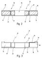
- an insulating film 22 is shown in cross section, enlarged and not to scale, as can be used with the temperature monitor 10 from FIG. 1.
- the insulating film 22 has a film 24, for example made of Teflon, Kapton, Nomex or the like.
- the film 24 is provided on both sides with resistance material 25, for example a thermistor material, a carbon film resistor or the like can be.
- resistance material 25 for example a thermistor material, a carbon film resistor or the like can be.
- an opening 26 is provided in the film 24, which is put over the movable contact part 17, as can be seen in FIG. 1.
- the insulating film 22 comes into contact with the cover part 12 via its upper resistance material 27 at its edge 28, while it lies on the shoulder 13 via its lower resistance material 29 at its edge 31 and is in electrical contact with the lower housing part 11 is located.
- vias 32 are provided which connect the upper resistance material 27 to the lower resistance material 29.
- the heating resistor 23 formed from the upper and lower resistance material 27, 29 is connected on the one hand to the cover part 12 and on the other hand to the lower housing part 11, so that it is connected in parallel to the bimetallic switching mechanism 15. In this way, the heating resistor 23 can provide the self-holding function of the new temperature monitor 10, which has already been discussed in detail.
- the resistance value can also be set via the distance of the plated-through holes 32 from the outer edges 28, 31, namely the more this plated-through hole lies at the edges 28, 31, the less the series connection from the two resistance areas, provided the other geometrical and electrical ones Properties are not changed.
- the through-contacts 32 can also be dispensed with, provided that that between the upper resistance material 27 and the lower resistance material 29 in the axial direction Direction measured resistance value is large enough to achieve the desired heating function when the bimetal switchgear is open.
- the heating resistor 23 is bridged by the latter anyway, so that its resistance value does not impair the function of the temperature monitor 10.
- the film 24 itself can be a PTC film 24 ', so that the upper and lower resistance material 27, 29 and the plated-through holes 32 can be dispensed with entirely.
- FIG. 3 shows a further exemplary embodiment of the new insulating film 22, as can be used with the temperature monitor 10 from FIG. 1.
- the film 24 here has 33 conductor tracks 34 on its upper side, which are connected via the plated-through holes 32 to a lower resistance material 29 on its lower side 35.
- the conductor tracks 34 extend essentially radially on the upper side 33 and open into a preferably circular conductor track 36 in the region of the edge 28.
- the heating resistor 23 is essentially formed by the lower resistance material 29, the conductor tracks 34, 36 and the Vias 32 are used only for the electrical connection between the lower resistance material 29 and the cover part 12.
- the lower resistance material 39 rests on the shoulder 13, so that the heating resistor 23 is also connected in parallel to the bimetallic switching mechanism 15 here.
- the conductor tracks 32, 34, 36 can also have tracks made of resistance material be, which can be arranged both on the top 33 and on the bottom 35.
- the heating resistor 23 is formed only by the resistance values of the resistance bands 32, 34, 36.
- the insulating film 22 of Fig. 3 is shown in a plan view, in which it can be seen that the resistance tracks 34, 36 cover the film 24 only in regions, the size of the cover, that is, the selected geometry, the resistance value of the heating resistor 23 determined.
- the insulating film 22 has resistance tracks 34, 36 both on its upper side 33 and on its lower side, as shown in FIG. 4.
- the film 24 can generally be made from a PTC thermistor material that has a non-specific positive temperature coefficient. However, it is also possible to directly use a PTC film with precisely set temperature-dependent resistance behavior as film 22, 24.
- the film 24 is made of conductive material and the conductor or resistance tracks 32, 34, 36 provide the resistance value of the heating resistor 23, then it may be necessary to close the free area 38 between the conductor tracks 34 with an intermediate layer of further insulating material 39 provided that on both sides of the insulating film 24 provides partial insulation to the lower housing part 11 or cover part 12 and, if the switching mechanism 15 is switched, possibly insulates the bimetallic disc 18 from the heating resistor 23.
Landscapes
- Physics & Mathematics (AREA)
- Thermal Sciences (AREA)
- Thermally Actuated Switches (AREA)
- Thermistors And Varistors (AREA)
- Control Of Temperature (AREA)
Applications Claiming Priority (2)
| Application Number | Priority Date | Filing Date | Title |
|---|---|---|---|
| DE19514853A DE19514853C2 (de) | 1995-04-26 | 1995-04-26 | Temperaturwächter mit einem bei Übertemperatur schaltenden Bimetall-Schaltwerk |
| DE19514853 | 1995-04-26 |
Publications (3)
| Publication Number | Publication Date |
|---|---|
| EP0740323A2 true EP0740323A2 (fr) | 1996-10-30 |
| EP0740323A3 EP0740323A3 (fr) | 1998-04-22 |
| EP0740323B1 EP0740323B1 (fr) | 2002-04-03 |
Family
ID=7760123
Family Applications (1)
| Application Number | Title | Priority Date | Filing Date |
|---|---|---|---|
| EP96100742A Expired - Lifetime EP0740323B1 (fr) | 1995-04-26 | 1996-01-19 | Thermostat avec un dispositif interrupteur à bimétal commutant en cas de surchauffe |
Country Status (7)
| Country | Link |
|---|---|
| US (1) | US5721525A (fr) |
| EP (1) | EP0740323B1 (fr) |
| AT (1) | ATE215732T1 (fr) |
| DE (2) | DE19514853C2 (fr) |
| DK (1) | DK0740323T3 (fr) |
| ES (1) | ES2174984T3 (fr) |
| PT (1) | PT740323E (fr) |
Cited By (3)
| Publication number | Priority date | Publication date | Assignee | Title |
|---|---|---|---|---|
| EP2775495A1 (fr) * | 2013-03-04 | 2014-09-10 | Marcel P. Hofsaess | Commutateur thermosensible avec plaque isolante |
| DE102022134379B3 (de) | 2022-12-21 | 2024-02-08 | Marcel P. HOFSAESS | Temperaturabhängiger Schalter |
| EP4425522A1 (fr) * | 2023-02-28 | 2024-09-04 | Marcel P. Hofsaess | Commutateur dépendant de la température |
Families Citing this family (11)
| Publication number | Priority date | Publication date | Assignee | Title |
|---|---|---|---|---|
| DE19639942C2 (de) * | 1996-09-27 | 1999-07-01 | Siemens Matsushita Components | Thermische Sicherung |
| DE19752581C2 (de) * | 1997-11-27 | 1999-12-23 | Marcel Hofsaes | Schalter mit einem temperaturabhängigen Schaltwerk |
| DE19827113C2 (de) * | 1998-06-18 | 2001-11-29 | Marcel Hofsaes | Temperaturabhängiger Schalter mit Stromübertragungsglied |
| US6229121B1 (en) * | 1999-07-23 | 2001-05-08 | Industrial Technology Research Institute | Integrated thermal buckling micro switch with electric heater and sensor |
| KR100637975B1 (ko) * | 2002-05-07 | 2006-10-23 | 가부시키가이샤 우부카타 세이사쿠쇼 | 서멀 프로텍터 |
| US20080055038A1 (en) * | 2006-08-31 | 2008-03-06 | Honeywell International Inc. | Thermal switch strike pin |
| CN102007561B (zh) * | 2008-04-18 | 2014-07-02 | 泰科电子日本合同会社 | 电路保护装置 |
| WO2009144771A1 (fr) * | 2008-05-30 | 2009-12-03 | 株式会社生方製作所 | Interrupteur à actionnement thermique |
| DE102013108508A1 (de) | 2013-08-07 | 2015-02-12 | Thermik Gerätebau GmbH | Temperaturabhängiger Schalter |
| DE102019125453B4 (de) * | 2019-09-20 | 2025-04-30 | Marcel P. HOFSAESS | Temperaturabhängiger Schalter |
| DE102022134380B3 (de) * | 2022-12-21 | 2024-02-08 | Marcel P. HOFSAESS | Temperaturabhängige Schaltwerke und temperaturabhängiger Schalter mit einem solchen Schaltwerk |
Family Cites Families (10)
| Publication number | Priority date | Publication date | Assignee | Title |
|---|---|---|---|---|
| DE2121802C3 (de) * | 1971-05-03 | 1974-10-24 | Thermik-Geraetebau Gmbh + Co, 7530 Pforzheim | Temperaturwächter |
| DE3644514A1 (de) * | 1986-12-24 | 1988-07-07 | Inter Control Koehler Hermann | Bimetallschalter |
| DE3710672C2 (de) * | 1987-03-31 | 1997-05-15 | Hofsaes Geb Zeitz Ulrika | Temperaturwächter mit einem Gehäuse |
| US4878038A (en) * | 1987-12-07 | 1989-10-31 | Tsai James T | Circuit protection device |
| JP2585148B2 (ja) * | 1991-04-05 | 1997-02-26 | ウチヤ・サーモスタット株式会社 | フィルム状発熱体内蔵型サーモスタット |
| DE4142716C2 (de) * | 1991-12-21 | 1997-01-16 | Microtherm Gmbh | Thermoschalter |
| DE4206157A1 (de) * | 1992-02-28 | 1993-09-16 | Hofsass P | Thermoschalter |
| DE9214940U1 (de) * | 1992-11-03 | 1992-12-17 | Thermik Geraetebau Gmbh, 7530 Pforzheim | Temperaturwächter |
| DE4335639A1 (de) * | 1993-10-13 | 1995-04-20 | Eaw Relaistechnik Gmbh | Thermoschalter mit Bimetallschnappscheibe und elektrischer/thermischer Verhinderung des automatischen Rückschnappens der Bimetallschnappscheibe |
| DE9320737U1 (de) * | 1993-10-13 | 1995-01-05 | EAW Relaistechnik GmbH, 10317 Berlin | Thermoschalter mit Bimetallschnappscheibe und elektrischer/thermischer Verhinderung des automatischen Rückschnappens der Bimetallschnappscheibe |
-
1995
- 1995-04-26 DE DE19514853A patent/DE19514853C2/de not_active Expired - Fee Related
-
1996
- 1996-01-19 AT AT96100742T patent/ATE215732T1/de active
- 1996-01-19 EP EP96100742A patent/EP0740323B1/fr not_active Expired - Lifetime
- 1996-01-19 PT PT96100742T patent/PT740323E/pt unknown
- 1996-01-19 ES ES96100742T patent/ES2174984T3/es not_active Expired - Lifetime
- 1996-01-19 DE DE59608984T patent/DE59608984D1/de not_active Expired - Lifetime
- 1996-01-19 DK DK96100742T patent/DK0740323T3/da active
- 1996-04-24 US US08/636,944 patent/US5721525A/en not_active Expired - Lifetime
Cited By (5)
| Publication number | Priority date | Publication date | Assignee | Title |
|---|---|---|---|---|
| EP2775495A1 (fr) * | 2013-03-04 | 2014-09-10 | Marcel P. Hofsaess | Commutateur thermosensible avec plaque isolante |
| DE102022134379B3 (de) | 2022-12-21 | 2024-02-08 | Marcel P. HOFSAESS | Temperaturabhängiger Schalter |
| EP4391000A1 (fr) | 2022-12-21 | 2024-06-26 | Marcel P. Hofsaess | Commutateur dépendant de la température |
| US12586743B2 (en) | 2022-12-21 | 2026-03-24 | Marcel P. HOFSAESS | Temperature-dependent switch |
| EP4425522A1 (fr) * | 2023-02-28 | 2024-09-04 | Marcel P. Hofsaess | Commutateur dépendant de la température |
Also Published As
| Publication number | Publication date |
|---|---|
| EP0740323B1 (fr) | 2002-04-03 |
| DK0740323T3 (da) | 2002-06-17 |
| EP0740323A3 (fr) | 1998-04-22 |
| ATE215732T1 (de) | 2002-04-15 |
| DE19514853C2 (de) | 1997-02-27 |
| DE19514853A1 (de) | 1996-11-07 |
| ES2174984T3 (es) | 2002-11-16 |
| DE59608984D1 (de) | 2002-05-08 |
| PT740323E (pt) | 2002-07-31 |
| US5721525A (en) | 1998-02-24 |
Similar Documents
| Publication | Publication Date | Title |
|---|---|---|
| DE4428226C1 (de) | Temperaturwächter | |
| DE19527253B4 (de) | Nach dem Baukastenprinzip aufgebauter Temperaturwächter | |
| DE102008048554B3 (de) | Temperaturabhängiger Schalter | |
| EP0756301B1 (fr) | Thermostat | |
| DE19604939C2 (de) | Schalter mit einem temperaturabhängigen Schaltwerk | |
| EP2874171B1 (fr) | Mécanisme de commutation variable avec la température | |
| EP0920044B1 (fr) | Interrupteur avec un mécanisme de commutation sensible à la température | |
| EP0740323B1 (fr) | Thermostat avec un dispositif interrupteur à bimétal commutant en cas de surchauffe | |
| DE102011119632B3 (de) | Temperaturabhängiges Schaltwerk | |
| WO2008113489A1 (fr) | Commutateur dépendant de la température et mécanisme de commutation prévu à cet effet | |
| EP0794546B1 (fr) | Interrupteur avec un mécanisme de commutation sensible à la température | |
| DE102013102006A1 (de) | Temperaturabhängiger Schalter | |
| DE4142716C2 (de) | Thermoschalter | |
| DE102011119637B4 (de) | Temperaturabhängiger Schalter mit einem temperaturabhängigen Schaltwerk sowie Verfahren zum Herstellen eines solchen Schalters | |
| DE19636640C2 (de) | Schalter mit einem Sicherheitselement | |
| EP0858091B1 (fr) | Dispositif de protection d'un appareil | |
| EP0887827B1 (fr) | Interrupteur avec un mécanisme de commutation sensible à la température | |
| DE19546004C2 (de) | Schalter mit einem bei Übertemperatur schaltenden Schaltwerk | |
| EP0778597A2 (fr) | Interrupteur avec un mécanisme de commutation actionné une température excessive | |
| DE102019111279B4 (de) | Temperaturabhängiger Schalter | |
| DE3587064T2 (de) | Thermostat. | |
| DE102023104839B3 (de) | Temperaturabhängiger Schalter | |
| DE102022134379B3 (de) | Temperaturabhängiger Schalter |
Legal Events
| Date | Code | Title | Description |
|---|---|---|---|
| PUAI | Public reference made under article 153(3) epc to a published international application that has entered the european phase |
Free format text: ORIGINAL CODE: 0009012 |
|
| AK | Designated contracting states |
Kind code of ref document: A2 Designated state(s): AT BE CH DE DK ES FR GB IE IT LI NL PT SE |
|
| PUAL | Search report despatched |
Free format text: ORIGINAL CODE: 0009013 |
|
| AK | Designated contracting states |
Kind code of ref document: A3 Designated state(s): AT BE CH DE DK ES FR GB IE IT LI NL PT SE |
|
| RAP1 | Party data changed (applicant data changed or rights of an application transferred) |
Owner name: HOFSAESS, MARCEL |
|
| 17P | Request for examination filed |
Effective date: 19980507 |
|
| 17Q | First examination report despatched |
Effective date: 19991118 |
|
| GRAG | Despatch of communication of intention to grant |
Free format text: ORIGINAL CODE: EPIDOS AGRA |
|
| GRAG | Despatch of communication of intention to grant |
Free format text: ORIGINAL CODE: EPIDOS AGRA |
|
| GRAH | Despatch of communication of intention to grant a patent |
Free format text: ORIGINAL CODE: EPIDOS IGRA |
|
| GRAH | Despatch of communication of intention to grant a patent |
Free format text: ORIGINAL CODE: EPIDOS IGRA |
|
| REG | Reference to a national code |
Ref country code: GB Ref legal event code: IF02 |
|
| GRAA | (expected) grant |
Free format text: ORIGINAL CODE: 0009210 |
|
| AK | Designated contracting states |
Kind code of ref document: B1 Designated state(s): AT BE CH DE DK ES FR GB IE IT LI NL PT SE |
|
| REF | Corresponds to: |
Ref document number: 215732 Country of ref document: AT Date of ref document: 20020415 Kind code of ref document: T |
|
| REG | Reference to a national code |
Ref country code: CH Ref legal event code: NV Representative=s name: TROESCH SCHEIDEGGER WERNER AG Ref country code: CH Ref legal event code: EP |
|
| REF | Corresponds to: |
Ref document number: 59608984 Country of ref document: DE Date of ref document: 20020508 |
|
| REG | Reference to a national code |
Ref country code: IE Ref legal event code: FG4D Free format text: GERMAN |
|
| REG | Reference to a national code |
Ref country code: DK Ref legal event code: T3 |
|
| GBT | Gb: translation of ep patent filed (gb section 77(6)(a)/1977) |
Effective date: 20020626 |
|
| REG | Reference to a national code |
Ref country code: PT Ref legal event code: SC4A Free format text: AVAILABILITY OF NATIONAL TRANSLATION Effective date: 20020412 |
|
| ET | Fr: translation filed | ||
| REG | Reference to a national code |
Ref country code: ES Ref legal event code: FG2A Ref document number: 2174984 Country of ref document: ES Kind code of ref document: T3 |
|
| PLBE | No opposition filed within time limit |
Free format text: ORIGINAL CODE: 0009261 |
|
| STAA | Information on the status of an ep patent application or granted ep patent |
Free format text: STATUS: NO OPPOSITION FILED WITHIN TIME LIMIT |
|
| 26N | No opposition filed |
Effective date: 20030106 |
|
| PGFP | Annual fee paid to national office [announced via postgrant information from national office to epo] |
Ref country code: PT Payment date: 20110117 Year of fee payment: 16 Ref country code: SE Payment date: 20110113 Year of fee payment: 16 |
|
| PGFP | Annual fee paid to national office [announced via postgrant information from national office to epo] |
Ref country code: CH Payment date: 20120123 Year of fee payment: 17 Ref country code: FR Payment date: 20120206 Year of fee payment: 17 Ref country code: IE Payment date: 20120124 Year of fee payment: 17 |
|
| PGFP | Annual fee paid to national office [announced via postgrant information from national office to epo] |
Ref country code: IT Payment date: 20120126 Year of fee payment: 17 Ref country code: GB Payment date: 20120120 Year of fee payment: 17 Ref country code: BE Payment date: 20120117 Year of fee payment: 17 Ref country code: DK Payment date: 20120119 Year of fee payment: 17 |
|
| REG | Reference to a national code |
Ref country code: PT Ref legal event code: MM4A Free format text: LAPSE DUE TO NON-PAYMENT OF FEES Effective date: 20120719 |
|
| PGFP | Annual fee paid to national office [announced via postgrant information from national office to epo] |
Ref country code: NL Payment date: 20120125 Year of fee payment: 17 |
|
| REG | Reference to a national code |
Ref country code: SE Ref legal event code: EUG |
|
| REG | Reference to a national code |
Ref country code: CH Ref legal event code: PCOW Free format text: MARCEL HOFSAESS;JECHABURGER WEG 56;99706 SONDERSHAUSEN (DE) |
|
| REG | Reference to a national code |
Ref country code: DE Ref legal event code: R082 Ref document number: 59608984 Country of ref document: DE Representative=s name: WITTE, WELLER & PARTNER, DE |
|
| PG25 | Lapsed in a contracting state [announced via postgrant information from national office to epo] |
Ref country code: SE Free format text: LAPSE BECAUSE OF NON-PAYMENT OF DUE FEES Effective date: 20120120 |
|
| PG25 | Lapsed in a contracting state [announced via postgrant information from national office to epo] |
Ref country code: PT Free format text: LAPSE BECAUSE OF NON-PAYMENT OF DUE FEES Effective date: 20120719 |
|
| REG | Reference to a national code |
Ref country code: FR Ref legal event code: CA Effective date: 20121031 |
|
| REG | Reference to a national code |
Ref country code: DE Ref legal event code: R082 Ref document number: 59608984 Country of ref document: DE Representative=s name: WITTE, WELLER & PARTNER PATENTANWAELTE MBB, DE Effective date: 20121017 Ref country code: DE Ref legal event code: R082 Ref document number: 59608984 Country of ref document: DE Representative=s name: WITTE, WELLER & PARTNER, DE Effective date: 20121017 Ref country code: DE Ref legal event code: R081 Ref document number: 59608984 Country of ref document: DE Owner name: HOFSAESS, MARCEL P., DE Free format text: FORMER OWNER: HOFSAESS, MARCEL, 75305 NEUENBUERG, DE Effective date: 20121017 |
|
| PGFP | Annual fee paid to national office [announced via postgrant information from national office to epo] |
Ref country code: AT Payment date: 20120111 Year of fee payment: 17 |
|
| PGFP | Annual fee paid to national office [announced via postgrant information from national office to epo] |
Ref country code: DE Payment date: 20130221 Year of fee payment: 18 |
|
| PGFP | Annual fee paid to national office [announced via postgrant information from national office to epo] |
Ref country code: ES Payment date: 20120126 Year of fee payment: 17 |
|
| BERE | Be: lapsed |
Owner name: *HOFSASS MARCEL Effective date: 20130131 |
|
| REG | Reference to a national code |
Ref country code: NL Ref legal event code: V1 Effective date: 20130801 |
|
| REG | Reference to a national code |
Ref country code: DK Ref legal event code: EBP |
|
| REG | Reference to a national code |
Ref country code: CH Ref legal event code: PL |
|
| REG | Reference to a national code |
Ref country code: AT Ref legal event code: MM01 Ref document number: 215732 Country of ref document: AT Kind code of ref document: T Effective date: 20130131 |
|
| GBPC | Gb: european patent ceased through non-payment of renewal fee |
Effective date: 20130119 |
|
| REG | Reference to a national code |
Ref country code: IE Ref legal event code: MM4A |
|
| REG | Reference to a national code |
Ref country code: FR Ref legal event code: ST Effective date: 20130930 |
|
| PG25 | Lapsed in a contracting state [announced via postgrant information from national office to epo] |
Ref country code: NL Free format text: LAPSE BECAUSE OF NON-PAYMENT OF DUE FEES Effective date: 20130801 Ref country code: BE Free format text: LAPSE BECAUSE OF NON-PAYMENT OF DUE FEES Effective date: 20130131 Ref country code: CH Free format text: LAPSE BECAUSE OF NON-PAYMENT OF DUE FEES Effective date: 20130131 Ref country code: AT Free format text: LAPSE BECAUSE OF NON-PAYMENT OF DUE FEES Effective date: 20130131 Ref country code: LI Free format text: LAPSE BECAUSE OF NON-PAYMENT OF DUE FEES Effective date: 20130131 |
|
| PG25 | Lapsed in a contracting state [announced via postgrant information from national office to epo] |
Ref country code: FR Free format text: LAPSE BECAUSE OF NON-PAYMENT OF DUE FEES Effective date: 20130131 Ref country code: GB Free format text: LAPSE BECAUSE OF NON-PAYMENT OF DUE FEES Effective date: 20130119 |
|
| PG25 | Lapsed in a contracting state [announced via postgrant information from national office to epo] |
Ref country code: IT Free format text: LAPSE BECAUSE OF NON-PAYMENT OF DUE FEES Effective date: 20130119 |
|
| PG25 | Lapsed in a contracting state [announced via postgrant information from national office to epo] |
Ref country code: DK Free format text: LAPSE BECAUSE OF NON-PAYMENT OF DUE FEES Effective date: 20130131 Ref country code: IE Free format text: LAPSE BECAUSE OF NON-PAYMENT OF DUE FEES Effective date: 20130119 |
|
| REG | Reference to a national code |
Ref country code: ES Ref legal event code: FD2A Effective date: 20140324 |
|
| PG25 | Lapsed in a contracting state [announced via postgrant information from national office to epo] |
Ref country code: ES Free format text: LAPSE BECAUSE OF NON-PAYMENT OF DUE FEES Effective date: 20130120 |
|
| REG | Reference to a national code |
Ref country code: DE Ref legal event code: R119 Ref document number: 59608984 Country of ref document: DE |
|
| PG25 | Lapsed in a contracting state [announced via postgrant information from national office to epo] |
Ref country code: DE Free format text: LAPSE BECAUSE OF NON-PAYMENT OF DUE FEES Effective date: 20140801 |
|
| REG | Reference to a national code |
Ref country code: DE Ref legal event code: R119 Ref document number: 59608984 Country of ref document: DE Effective date: 20140801 |