EP0740433A2 - Optischer Sender - Google Patents
Optischer Sender Download PDFInfo
- Publication number
- EP0740433A2 EP0740433A2 EP96106685A EP96106685A EP0740433A2 EP 0740433 A2 EP0740433 A2 EP 0740433A2 EP 96106685 A EP96106685 A EP 96106685A EP 96106685 A EP96106685 A EP 96106685A EP 0740433 A2 EP0740433 A2 EP 0740433A2
- Authority
- EP
- European Patent Office
- Prior art keywords
- circuit
- sample
- hold
- input signal
- light emitting
- Prior art date
- Legal status (The legal status is an assumption and is not a legal conclusion. Google has not performed a legal analysis and makes no representation as to the accuracy of the status listed.)
- Withdrawn
Links
Images


Classifications
-
- H—ELECTRICITY
- H04—ELECTRIC COMMUNICATION TECHNIQUE
- H04B—TRANSMISSION
- H04B10/00—Transmission systems employing electromagnetic waves other than radio-waves, e.g. infrared, visible or ultraviolet light, or employing corpuscular radiation, e.g. quantum communication
- H04B10/50—Transmitters
- H04B10/501—Structural aspects
- H04B10/503—Laser transmitters
- H04B10/504—Laser transmitters using direct modulation
-
- H—ELECTRICITY
- H04—ELECTRIC COMMUNICATION TECHNIQUE
- H04B—TRANSMISSION
- H04B10/00—Transmission systems employing electromagnetic waves other than radio-waves, e.g. infrared, visible or ultraviolet light, or employing corpuscular radiation, e.g. quantum communication
- H04B10/50—Transmitters
- H04B10/564—Power control
Definitions
- the present invention relates to an optical transmitter apparatus which controls an output level when a digital electrical signal input, continuously or in bursts, is converted into a light signal.
- Fig. 13 discloses an optical power outputting apparatus as an example of a conventional light emitting control apparatus. This apparatus has been described on page 55-60, volume 11 of the technical report OCS-93-53, 1993 of the Institute of Electronics, Information and Communication Engineers of Japan.
- the optical power outputting apparatus is comprised of a buffer circuit 1, a voltage-to-current converter 2, a light emitting element 3, an optical fiber 4, a monitoring circuit 5, a first peak detection circuit 6, a differential amplifier 7, a second peak detection circuit 8, a control circuit 9, and a light signal off detection circuit 10.
- an automatic power control operation (hereinafter referred to as the APC operation) is described. It is assumed herein that an input signal has low and high levels.
- the input signal After having been reformed in its waveform via the buffer circuit 1, the input signal is divided into two branched signals. The first of the two branched signals is outputted to the voltage-to-current converter 2. In the voltage-to-current converter 2, a current signal which is turned on and off corresponding to the input signal's on/off state is generated. The current signal drives the light emitting element 3 to output a light signal which is sent to the optical fiber 4.
- a fraction of the optical output of the light emitting element 3 is converted into a monitoring signal via the monitoring circuit 5.
- the monitoring signal is then input into the second peak detection circuit 8.
- a peak value of the output of the monitoring circuit 5 is detected and is outputted to the differential amplifier 7.
- the second of the branched signals from the buffer circuit 1 is input into the first peak detection circuit 6.
- a peak value is detected, and outputted to the differential amplifier 7.
- the differential amplifier 7 a difference of the peak values between the first peak detection circuit 6 and the second peak detection circuit 8 is detected, amplified, and input into the control circuit 9.
- the amplitude of the current from the voltage-to-current converter 2 is adjusted by the control circuit 9 so as to keep the difference between the inputs of the differential amplifier 7 almost zero at all times.
- the optical output of the light emitting element 3 is controlled to be constant at all times.
- a detection level from the second peak detection circuit 8 is compared with a predetermined reference level, and when the level falls to or below the predetermined reference level, a light signal off alarm is generated.
- Japanese Unexamined Patent Application HEI2-193426 discloses a related art in which, with the data input, a mark ratio of the data (used herein to mean a ratio of a mark period to a predetermined data transmission period) is detected, and an alarm reference level is set, responsive to the mark ratio.
- the mark level does not vary with the mark ratio.
- Japanese Unexamined Patent Application HEI4-249721 discloses another related art in which detection of data input is performed in one peak detection circuit and monitoring of the optical output is performed in another peak detection circuit. Using the outputs of these peak detection circuits, a certain result can be obtained and calculated via a predetermined mathematical algorithm. Then, by using the result, a part failure can be identified.
- time constants of the first peak detection circuit 6 and the second peak detection circuit 8 for a peak-hold operation are set to become or exceed the maximum burst interval. Accordingly, when an initial rise of the subsequent signal input in bursts occurs after the peak detection circuits have been discharged fully with no signal input for a long time, it will take time for the first and second peak detection circuits to recognize a final peak input state. Therefore, time is necessary to stabilize the optical output.
- alarm generation is controlled by a change of the output level of the second peak detection circuit 8. This creates a problem in that an alarm is generated by a no data input condition which would not normally have generated the alarm.
- the present invention is made to solve the above-described problems. It is, therefore, an object of the present invention to provide a light emitting control apparatus which immediately recognizes a rise of the input and initiates a following operation, and which retains the output level accurately and continuously for a long period of time even if the mark ratio of input data fluctuates greatly.
- a light emitting control apparatus to which the present invention is applicable is provided with a light emitting element which is responsive to an input signal, and a monitoring circuit which detects the output level of the light emitting element.
- the apparatus aims to control low and high output levels of the light emitting element.
- the light emitting control apparatus comprises a sample-and-hold circuit and an amplifier.
- the sample-and-hold circuit has a sample mode and a hold mode.
- the sample-and-hold circuit is put into the sample mode and tracks the output level which has been detected by the monitoring circuit.
- the sample-and-hold circuit is put into the hold mode and holds the output level determined when it switched into the hold mode.
- the amplifier receives the output level from the sample-and-hold circuit and controls the low output level or the high output level of the light emitting element by providing the correct output level to the light emitting element.
- the light emitting control apparatus may further comprise a second sample-and-hold circuit and a second amplifier.
- the second sample-and-hold circuit complementarily functions with the first sample-and-hold circuit such that when the first sample-and-hold circuit is in the hold mode, the second sample-and-hold circuit is put into the sample mode and tracks the output level which has been detected by the monitoring circuit.
- the second sample-and-hold circuit is put into the hold mode and holds the output level determined when it switched into the hold mode.
- the second amplifier receives the output of the second sample-and-hold circuit and controls the other of the low output level or the high output level of the light emitting element, not controlled by the first sample-and-hold circuit.
- the light emitting control apparatus may further comprise a burst detection circuit.
- the burst detection circuit detects an off-state of the input signal when the signal has not been input for more than a predetermined period.
- the burst detection circuit controls the sample-and-hold circuit while the input signal is detected.
- the light emitting control apparatus may further comprise the burst detection circuit which functions in the same manner as the sample-and-hold circuit, and a light off detector.
- the burst detection circuit has the sample mode and the hold mode.
- the burst detection circuit tracks the level of the input signal in the sample mode while the input signal is in the mark state.
- the burst detection circuit in the hold mode, holds the level of the input signal determined when it switched into the hold mode.
- the light off detector detects a cutoff of the output level of the light emitting element by comparing the output of the sample-and-hold circuit with the output of the burst detection circuit.
- the sample-and-hold circuit of the light emitting control apparatus has a first emitter follower.
- the first emitter follower tracks the output level of the monitoring circuit and outputs the output level to a resistor-capacitor serial circuit.
- the sample-and-hold circuit outputs the voltage of a capacitor in the resistor-capacitor serial circuit through a second emitter follower as the output of the sample-and-hold circuit.
- the current of the first emitter follower is turned on/off by a sample-and-hold control circuit which is turned on/off with a control signal.
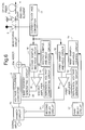
- Fig. 1 illustrates a configuration of a light emitting control apparatus according to embodiment 1 of the present invention.
- the same reference numerals are assigned to the parts performing similar functions as in Fig. 13, and their description will be omitted.
- reference numeral 11 denotes a current-to-voltage converter
- 12 denotes a first sample-and hold circuit
- 13 denotes a reference voltage generating circuit
- 14 denotes a first amplifier
- 15 denotes a first sample-and-hold control circuit.
- the converted signal with high and low levels is used as a sample-and-hold control signal.
- An input signal is input into the voltage-to-current converter 2 and is converted into a current signal which is turned on and off corresponding to the input electrical signal's on/off state.
- the output current of the voltage-to-current converter 2 drives the light emitting element 3 to output a light signal which is turned on and off.
- the light signal is then sent to the optical fiber 4.
- a fraction of the output of the light emitting element 3 is converted into a current signal via the monitoring circuit 5 used in the monitoring operation. Then, the current signal is converted into a voltage signal via the current-to-voltage converter 11.
- the output of the current-to-voltage converter 11 is divided into two branched outputs, and one of the two branched outputs is input into the first sample-and-hold circuit 12, where a peak value is detected. A difference between this peak value and a reference voltage from the reference voltage generating circuit 13 is detected in the first amplifier 14.
- the first amplifier 14 adjusts the amplitude of the current from the voltage-to-current converter 2 to cancel the difference and keep the optical output of the light emitting element constant.
- the other one of the two branched outputs of the current-to-voltage converter 11 is input into the first sample-and-hold control circuit 15 as the sample-and-hold control signal.
- the first sample-and-hold control circuit 15 by comparing the input with the reference voltage, for example, an electric current is drawn from the first sample-and-hold circuit 12 when the sample-and-hold control signal is significant or the optical output is in the mark state, designated "1", and the first sample-and-hold circuit is put into the sample mode. In other words, the first sample-and-hold circuit 12 tracks an input very quickly.
- the optical output When the optical output is in the space state, designated "0", the electrical-current tracking of the first sample-and-hold circuit 12 is stopped, and the first sample-and-hold circuit 12 is put into the hold mode.
- a time constant for the hold mode may be selected arbitrarily. However, the time constant for the hold mode is usually determined to be large, thus stabilizing the output of the first sample-and-hold circuit 12.
- this embodiment of the present invention describes the APC operation that is performed when the input signal is used as the sample-and-hold control signal.
- reference numeral 16 denotes a branch circuit
- 17 denotes a first delay circuit.
- the same APC operation as in embodiment 1 is performed, except that the sample-and-hold control signal is obtained from the input side of the light emitting control apparatus.
- An input signal is divided into two branched signals via the branch circuit 16.
- One of the two branched signals is input into the voltage-to-current converter 2, where it is converted into a current signal which is turned on and off corresponding to the input signal's on/off state.
- the output current of the voltage-to-current converter 2 drives the light emitting element 3 to output a light signal which is turned on and off and is sent to the optical fiber 4.
- a fraction of the output of the light emitting element 3 is converted into a current signal via the monitoring circuit 5 used in the monitoring operation, and is further converted into a voltage signal via the current-to-voltage converter 11.
- the output of the current-to-voltage converter 11 is input into the first sample-and-hold circuit 12, where a peak value is detected.
- the first amplifier 14 a difference between this peak value and the reference voltage from the reference voltage generating circuit 13 is detected.
- the first amplifier 14 adjusts the amplitude of the current from the voltage-to-current converter 2 so as to cancel the difference between the peak and reference voltages and keep the optical output of the light emitting element constant.
- the other one of the two branched signals outputted from the branch circuit 16, passes through the first delay circuit 17 and is input into the first sample-and-hold control circuit 15 as the sample-and-hold control signal.
- the sample-and-hold circuit 12 is put into the sample mode.
- the optical output is designated "0"
- the first sample-and-hold circuit 12 is put into the hold mode.
- the sample-and-hold control signal is adjusted in its time-delay by the first delay circuit 17 so as to be in phase with the input into the first sample-and-hold circuit 12.
- Fig. 3 depicts a light emitting control apparatus according to this embodiment of the present invention .
- reference numeral 18 denotes a second sample-and-hold circuit
- 19 denotes a second amplifier
- 20 denotes a bias current generating circuit
- 21 denotes an inverter
- 22 denotes a second sample-and-hold control circuit.
- the output of the monitoring circuit of the light emitting element is used as the sample-and-hold control signal.
- the sample mode and the hold mode are inverted. Consequently, the sample-and-hold period is different from the previous embodiments.
- An input signal is input into the voltage-to-current converter 2, and is converted into a current signal which is turned on and off corresponding to the input signal's on/off state.
- the output current of the voltage-to-current converter 2 drives the light emitting element 3 to output a light signal which is sent to the optical fiber 4.
- a fraction of the optical output of the light emitting element 3 is detected in the monitoring circuit 5, and is converted into a voltage signal via the current-to-voltage converter 11.
- the voltage signal is then input into the second sample-and-hold circuit 18.
- a peak value of the space level of data is detected, as will be described later.
- the peak value of the space level and the reference voltage from the reference voltage generating circuit 13 are compared in the second amplifier 19.
- the second amplifier 19 regulates the current for the bias current generating circuit 20 to cancel a difference between the peak value and the reference voltage, thus stabilizing a bias level when the input signal is in the space level.
- the other one of the two branched outputs of the current-to-voltage converter 11 is inverted in its state via the inverter 21, and is input into the second sample-and-hold control circuit 22 as the sample-and-hold control signal.
- the second sample-and-hold control circuit 22 when the sample-and-hold control signal is significant, or the optical output is in the space state designated "0", the second sample-and-hold circuit 18 is put into the sample mode.
- the optical output is in the mark state designated "1"
- the second sample-and-hold circuit 18 is put into the hold mode.
- this embodiment of the present invention describes a bias current control operation that is performed when the input signal is used the sample-and-hold control signal.
- control of the space level of data is performed in the form of sample-and-hold control by means of the input signal as described in embodiment 2.
- reference numeral 23 denotes a branch circuit provided with an inversion output, and 24 denotes a second delay circuit.
- An input signal is divided into two branched signals via the branch circuit 23 provided with the inversion output.
- One of the two branched signals is input into the voltage-to-current converter 2 in its original state, and converted into a current signal which is turned on and off corresponding to the input electrical signal's on/off state.
- the output current of the voltage-to-current converter 2 drives the light emitting element 3 to output a light signal which is sent to the optical fiber 4.
- a fraction of the output of the light emitting element 3 is detected in the monitoring circuit 5, and is converted into a voltage signal via the current-to-voltage converter 11.
- the voltage signal is then input into the second sample-and-hold circuit 18, where a peak value of the space level of data is detected.
- the peak value of the space level of data and the reference voltage from the reference voltage generating circuit 13 are compared in the second amplifier 19.
- the second amplifier 19 regulates the current for the bias current generating circuit 20 to cancel a difference between the peak value and the reference voltage, stabilizing the bias level when the input signal is in the space level.
- the bias current from the bias current generating circuit 20 is then added to the current from the voltage-to-current converter 2 via the adder 20a.
- the other one of the two branched signals is inverted in its state upon outputted from the branch circuit 23, then passes through the second delay circuit 24, and is input into the second sample-and-hold control circuit 22 as the sample-and-hold control signal.
- the sample-and-hold control signal is adjusted in its time-delay in the same manner as that in embodiment 2.
- the second sample-and-hold control circuit 22 when the sample-and-hold control signal is significant, or the optical output is in the space state designated "0", the second sample-and-hold circuit 18 is put into the sample mode. When the optical output is designated "1", the second sample-and-hold circuit 18 is put into the hold mode.
- a light emitting control apparatus according to embodiment 5 of the present invention will be described in conjunction with Fig. 5.
- the output of the monitoring circuit of the light emitting element is used as the sample-and-hold control signal.
- An input signal is input into the voltage-to-current converter 2, and is converted into a current signal.
- the output current of the voltage-to-current converter 2 drives the light emitting element 3 to output a light signal which is sent to the optical fiber 4.
- a fraction of the output of the light emitting element 3 is detected in the monitoring circuit 5, and is converted into a voltage signal via the current-to-voltage converter 11.
- the output of the current-to-voltage converter 11 is divided into four branched outputs via the branch circuit 23.
- One of the four branched outputs is input into the second sample-and-hold circuit 18 in its original state, and as will be described later, a peak value of the space level of data is detected.
- the peak value of the space level and the reference voltage from the reference voltage generating circuit 13 are compared in the second amplifier 19.
- the second amplifier 19 regulates the current for the bias current generating circuit 20 so as to cancel a difference between the peak value of the space level of data and the reference voltage, stabilizing the bias level when the input signal is in the space level.
- the bias current from the bias current generating circuit 20 is then added to the current from the voltage-to-current converter 2 via the adder 20a.
- another one of the four branched outputs from the branch circuit 23 is inverted in its state, and is input into the second sample-and-hold control circuit 22 as the sample-and-hold control signal.
- the second sample-and-hold control circuit 22 when the sample-and-hold control signal is significant, or the optical output is in the space state designated "0", the second sample-and-hold circuit 18 is put into the sample mode. When the optical output is designated "1”, the second sample-and-hold circuit 18 is put into the hold mode.
- Another one of the four branched outputs from the above-described branch circuit 23 is input into the first sample-and-hold circuit 12 in its original state, and a peak value is detected. A difference of the peak value and the reference voltage from the reference voltage generating circuit 13 is detected in the first amplifier 14. In the first amplifier 14, the amplitude of the current from the voltage-to-current converter 2 is adjusted so as to cancel the difference and keep the optical output of the light emitting element constant.
- the last one of the four branched outputs of the branch circuit 23 is input into the first sample-and-hold control circuit 15 as the sample-and-hold control signal.
- the first sample-and-hold control circuit 15 when the sample-and-hold control signal is significant, or the optical output is designated "1", the first sample-and-hold circuit 12 is put into the sample mode. When the optical output is designated "0”, the first sample-and-hold circuit 12 is put into the hold mode.
- sample-and-hold control is performed for each bit of input data corresponding to the low and high levels of the input signal, and the first sample-and-hold circuit 12 tracks the output from the monitoring circuit very quickly. Furthermore, the bias current when the input signal is in the space level is controlled in a stable fashion.
- the input signal is branched into three branched signals via the branch circuit 23.
- One of the three branched signals is input into the voltage-to-current converter 2 in its original state.
- the other one of the three branched signals also in its original state, is input into the first sample-and-hold control circuit 15, after having been adjusted in its time delay via the first delay circuit 17.
- the last one of the three branched signals is input into the second sample-and-hold control circuit 22, after having been inverted in its state by the branch circuit 23 and adjusted in its time delay by the second delay circuit 24.
- the output of the monitoring circuit 5 is divided into two branched outputs after having been subjected to current-to-voltage conversion by the current-to-voltage converter 11.
- One of the two branched outputs is input into the first sample-and-hold circuit 12, and the other is input into the second sample-and-hold circuit 18. Then, a peak level detection and a space level detection are executed. Other operations are the same as in embodiment 5, and the APC operation and the bias current control operation are performed.
- a description will be directed to the case where the sample-and-hold control period is defined to be a period in which the input signal continues to be input in bursts.
- the bias current control operation will be described in conjunction with Fig. 7.
- reference numeral 25 denotes a burst detection circuit
- 26 denotes an input signal identifying circuit.
- the configuration of the burst detection circuit 25 is the same as that of the first sample-and-hold circuit 12 or the second sample-and-hold circuit 18.
- the time constant for the hold operation is small, and thus falls off to a "0" level as the space state of data continues for more than a predetermined period of time.
- the time constant may be set to an arbitrary value. Let us assume, for example, that the time constant is set to fall off to 0 when a period of 15 consecutive space states elapses. When the mark state of data input is present within that period, the burst detection circuit detects it as a signal input in bursts.
- the description will be directed only to the case where the input signal is used as a signal for controlling the second sample-and-hold circuit 22.
- the output of the monitoring circuit of the light emitting element is used as the sample-and-hold control signal. Therefore, the description about that in this case will be omitted.
- An input signal is divided into three branched signals via the branch circuit 23.
- One of the three branched signals is input into the voltage-to-current converter 2 in its original state.
- the other one of the three branched signals is inverted in its state within the branch circuit 23, and is input into the second sample-and-hold circuit 18 after being time delayed, and bias current control is performed as described in embodiment 4.
- the last one of the three branched signals is input into the burst detection circuit 25, where a peak value is detected.
- the peak value is compared with the reference voltage in the input signal identifying circuit 26, and the presence of the signal input is identified.
- the output of the input signal identifying circuit 26 is input into the bias current generating circuit 20.
- this embodiment of the present invention describes optical output off detection.
- reference numeral 27 denotes an optical output monitoring circuit, and 28 denotes a light off detector.
- the output of the first sample-and-hold circuit 12 is branched into two branched outputs.
- One of the two branched outputs is input into the first amplifier 14, and the other one is input into the optical output monitoring circuit 27.
- the optical output monitoring circuit 27 the output of the first sample-and-hold circuit 12 and the reference voltage from the reference voltage generating circuit 13 are compared, and the presence of the optical output is determined according to a predetermined reference value.
- the light off detector 28 When it is determined that no optical output is present in the optical output monitoring circuit 27, and that an input signal is being input into the optical transmitter via the input signal identifying circuit 26, the light off detector 28 generates a light off alarm signal.
- a light off alarm is generated only in the case of the failure of the optical transmitter.
- a light off alarm is not generated except in the case of the failure of the optical transmitter. Therefore, when a system provided with the optical transmitter according to the present invention detects an error, a part failure can be identified easily.
- Such a complex operation as previously described in the conventional related art, performed by combining gate circuits to identify an alarm-causing failure part is not needed.
- sample-and-hold circuit including the sample-and-hold control circuit is rather complicated.
- sample-and-hold circuit has the following characteristics:
- the input impedance of the circuit is high enough not to affect other circuits.
- the internal impedance of the circuit is high, and the circuit is excellent in the following property.
- the circuit When the sample-and-hold circuit is in the hold mode, the circuit retains the voltage level of the sample mode if the load impedance of the circuit connected thereto is not so low.
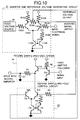
- the sample-and-hold circuit There are various circuit configurations for the sample-and-hold circuit. In this embodiment, a description will be directed to the circuit configuration for the first sample-and hold circuit 12 and the first sample-and-hold control circuit 15 shown in Fig. 9. Refer to previous drawings for references made to elements such as the monitoring circuit which have been left out of this drawing.
- the sample-and-hold control signal is generated by the conversion of the output of the monitoring circuit into a signal with high and low levels.
- reference numeral 29 denotes a switching circuit
- TrXX denotes a transistor
- CXX denotes a capacitor
- RXX denotes a resistance. (herein, XX represents numerals.)
- the output of the current-to-voltage converter 11 is divided into two branched outputs.
- One of the two branched outputs is input into the first sample-and-hold circuit 12.
- the first sample-and-hold circuit 12 is comprised of a transistor Tr1, a resistance R1, and a capacitor C1.
- the transistor Tr1 constitutes a first emitter follower.
- the other one of the two branched outputs of the current-to-voltage converter 11 is converted in its voltage level and input into the first sample-and-hold control circuit 15 as the control signal input and is used by the switching circuit 29 as the input for controlling the first sample-and-hold control circuit 15.
- Td1 Q1/Icollector
- Transistors Tr11 and Tr12 and a resistance R10 constitute a second emitter follower.
- the current Iout can be held to be almost one hundredth of the value obtained by an usual emitter follower. In this situation, the current Iout can be held to several tens of nanoamperes.
- the capacitor C1 has a capacitance of 1000pF and is charged with a voltage of 0.5V, the time constant for discharging the capacitor C1 becomes as large as 50ms.
- time constants for charging and discharging the capacitor can be varied with the rate of the signal to be transmitted. Accordingly, the APC operation can be accomplished rapidly.
- the time constant for discharging the capacitor can be set to be large by constituting and connecting the Darlington circuit to the sample-and-hold circuit.
- the second sample-and-hold circuit 18 is turned on/off by the second sample-and-hold control circuit 22.
- the input into the second sample-and-hold control circuit 22 is inverted so as to facilitate detection of the space level of data by inverting mark and space levels.
- An inverter and reference voltage generating circuit 31 is provided to provide the functions of inverting a signal input as well as providing a reference voltage.
- a fixed voltage source 30, and a second differential circuit constituted by the transistor Tr101 and the transistor 102 are provided within the inverter and reference voltage generating circuit 31.
- An input electrical signal is inverted in its state via the differential circuit and outputted to the second sample-and-hold control circuit 22 as the sample-and-hold control signal.
- a reference voltage is derived from a midpoint value of two outputs from the differential circuit and outputted to the second sample-and-hold control circuit 22.
- the reference voltage which represents the midpoint value of two outputs from the differential circuit, also changes. The reference voltage thus changes and remains in the middle range between the high level and the low level of data at all times.
- the above-described sample-and-hold control signal and reference voltage are input into the second sample-and-hold control circuit 22.
- the sample-and-hold control signal has been inverted in its state. Consequently, in the second sample-and-hold control circuit 22, when data is in the space state, the transistor Tr3 is turned ON by the inverted sample-and-hold control signal and the second sample-and-hold circuit 18 is put into the sample mode. Then, the capacitor C1 is charged up, and peak detection of the space level of data is executed. When data is in the mark state, the transistor Tr2 is turned ON. Thus, the transistor Tr1 and the transistor Tr3 are turned OFF. The second sample-and-hold circuit 18 is then put into the hold mode to retain the detected peak value of the space level of data.
- the inverter and reference voltage generating circuit 31 constituted by the transistors Tr101, Tr102, Tr103, and Tr104 may be used to avoid the influence of such factors as temperature variations.
- an in-phase signal responsive to the mark level of data is used as the sample-and-hold control signal, and when peak detection of the mark level of data is executed, the in-phase signal is outputted from the collector of the transistor Tr101.
- the output from the inverter and reference voltage generating circuit 31 can also be used to provide the reference voltage for the amplifier.
- the output of the current-to-voltage converter 11 is input into the differential circuit therein, and inverted in its state. Then the inverted signal is input into the second sample-and-hold control circuit 22 via the emitter follower and the second sample-and-hold circuit 18. The output of the midpoint value between two outputs from the differential circuit within the inverter and reference voltage generating circuit 31 is input into the second amplifier 19 via the other emitter follower as the reference voltage, and also input into the second sample-and-hold control circuit 22 after having been converted in its voltage level.
- the output of the current-to-voltage converter circuit 11 is inverted in its mark and space levels via the inverter and reference voltage generating circuit 31.
- the transistor Tr3 when data is in the space state, the transistor Tr3 is turned ON.
- the second sample-and-hold circuit 18 is then put into the sample mode, the capacitor C1 is charged up, and peak detection of the space level of data is executed.
- the transistor Tr2 When data is in the mark state, the transistor Tr2 is turned ON, and the transistors Tr1 and Tr3 are turned OFF.
- the second sample-and-hold circuit 18 is then put into the hold mode, and the detected peak value of the space level of data is retained.
- reference numeral 32 denotes a third sample-and-hold circuit
- reference numeral 33 denotes a third sample-and-hold control circuit
- the input signal is used as the sample-and-hold control signal.
- the operation of the first sample-and-hold circuit 12 and the first sample-and-hold control circuit 15 has been described hereinbefore. Therefore, the description about the operation will be omitted.
- the operation of the third sample-and-hold circuit 32 is performed in a similar manner to that of the first sample-and-hold circuit 12. Thus, the description about the operation will also be omitted.
- An input signal is divided into four branched signals.
- One of the four branched signals is input into the third sample-and-hold circuit 32.
- peak detection of the input signal is executed by the sample-and-hold control signal from the third sample-and-hold control circuit 33.
- peak detection of the optical output is executed by the sample-and-hold control signal from the first sample-and-hold control circuit 15.
- a detected peak value in the third sample-and-hold circuit 32 is zero. Since no optical output is provided, a detected peak value in the first sample-and-hold circuit 12 also becomes zero. Accordingly, in the first amplifier 14, a difference between the peak values of the first sample-and-hold circuit 12 and the third sample-and-hold circuit 32 is not detected. In this situation, the current gain of the voltage-to-current converter 2 becomes zero.
- an input signal When an input signal is input, it is divided into four branched signals. One of the four branched signals is input into the voltage-to-current converter 2, and another one of the four branched signals is input into the third sample-and-hold circuit 32. Now, let us assume that the time constant for charging the third sample-and-hold circuit 32 has been set to be from two to twenty bits of an input signal. A detected peak value in the third sample-and-hold circuit 32 thereby increases gradually. Now, the detected peak value is input into the first amplifier 14 as the reference voltage. Then, the current gain of the voltage-to-current converter 2 increases gradually, and the optical output rises gradually from the beginning of the signal input in bursts.
- the reference voltage When the reference voltage is set to be a predetermined value and no signal is being input, the reference voltage and the peak value of a zero level of the optical output are compared in the first amplifier 14. Consequently, the current gain of the voltage-to-current converter 2 attains the maximum value, and the light emitting element 3 emits the maximum amount of light at the beginning of the signal input in bursts.
- This embodiment provides effective control of the optical output at the beginning of the signal input in bursts.
- a light emitting control apparatus is provided with the sample-and-hold circuit which tracks the output level of the monitoring circuit, and the amplifier for negative feedback. Therefore, the apparatus can quickly respond to a signal input and keep correct mark and space levels of data for a long time.
- a light emitting control apparatus is provided with the sample-and-hold circuit which tracks the output level of the monitoring circuit, the second sample-and-hold circuit which complementarily functions therewith, and the amplifiers, each of which controls mark and space levels of data and supplies a bias current by accomplishing negative feedback. Therefore, the apparatus can quickly respond to a signal input and keep correct mark and space levels of data for a long time.
- an ideal waveform for optical transmission can be obtained by controlling a duty ratio of the "1" state to the "0" state of the optical output.
- a light emitting control apparatus is provided with the sample-and-hold circuit for a signal input, the burst detection circuit for the output of the monitoring circuit, and the light off detector. Therefore, in addition to the above-described effects, a part failure can be identified quickly during the mark period of data wherein a signal is actually being input.
- an optical transmitter according to the present invention is provided with a light emitting control apparatus with quick responsiveness. Therefore, an optical transmitter which tracks and quickly responds to a change of the input state, having the stable optical output level and high reliability can be obtained.
- the time constant for the sampling operation of the sample-and-hold circuit can be set to be in marked contrast with the time constant for the holding operation. Consequently, fast peak detection becomes possible. Since a detected peak value is retained for a long time, the APC circuit operates stably for the signal input in bursts for a long period.
- the time constant for detecting and controlling the input signal is set to be large. Consequently, excessive control for quick responsiveness to an input signal at the beginning of the signal input can be suppressed.
Landscapes
- Physics & Mathematics (AREA)
- Electromagnetism (AREA)
- Engineering & Computer Science (AREA)
- Computer Networks & Wireless Communication (AREA)
- Signal Processing (AREA)
- Optics & Photonics (AREA)
- Optical Communication System (AREA)
Applications Claiming Priority (2)
| Application Number | Priority Date | Filing Date | Title |
|---|---|---|---|
| JP10589495 | 1995-04-28 | ||
| JP105894/95 | 1995-04-28 |
Publications (1)
| Publication Number | Publication Date |
|---|---|
| EP0740433A2 true EP0740433A2 (de) | 1996-10-30 |
Family
ID=14419620
Family Applications (1)
| Application Number | Title | Priority Date | Filing Date |
|---|---|---|---|
| EP96106685A Withdrawn EP0740433A2 (de) | 1995-04-28 | 1996-04-26 | Optischer Sender |
Country Status (2)
| Country | Link |
|---|---|
| US (1) | US5978124A (de) |
| EP (1) | EP0740433A2 (de) |
Cited By (2)
| Publication number | Priority date | Publication date | Assignee | Title |
|---|---|---|---|---|
| EP0944186A3 (de) * | 1998-03-17 | 2004-07-07 | Fujitsu Limited | Treibereinrichtung für lichtemittierendes Element |
| EP1039665A3 (de) * | 1999-03-19 | 2004-11-10 | Fujitsu Limited | Optische Sendeschaltung |
Families Citing this family (13)
| Publication number | Priority date | Publication date | Assignee | Title |
|---|---|---|---|---|
| US5848044A (en) * | 1995-08-18 | 1998-12-08 | Kabushiki Kaisha Toshiba | Semiconductor laser driving circuit, semiconductor laser device, image recording apparatus, and optical disk apparatus |
| JPH11214183A (ja) * | 1998-01-22 | 1999-08-06 | Hochiki Corp | 発光回路 |
| US20020027690A1 (en) * | 2000-09-05 | 2002-03-07 | Meir Bartur | Fiber optic transceiver employing analog dual loop compensation |
| JP2002158396A (ja) * | 2000-11-22 | 2002-05-31 | Nec Corp | オートレーザーパワーコントロール回路 |
| JPWO2002069464A1 (ja) * | 2001-02-23 | 2004-07-02 | 富士通株式会社 | 光送信器 |
| JP4123791B2 (ja) * | 2001-03-05 | 2008-07-23 | 富士ゼロックス株式会社 | 発光素子駆動装置および発光素子駆動システム |
| CN100428592C (zh) * | 2001-03-05 | 2008-10-22 | 富士施乐株式会社 | 发光元件驱动装置和发光元件驱动系统 |
| CN1306502C (zh) * | 2002-09-24 | 2007-03-21 | 联发科技股份有限公司 | 标记形成效能信号产生方法及其装置 |
| JP4312573B2 (ja) * | 2003-10-27 | 2009-08-12 | 株式会社リコー | 半導体レーザ駆動回路 |
| JP2008182425A (ja) * | 2007-01-24 | 2008-08-07 | Denso Corp | フィルタ回路 |
| US7891570B2 (en) * | 2007-02-28 | 2011-02-22 | Microvision, Inc. | Photodiode with improved performance in ambient light |
| WO2014038239A1 (ja) | 2012-09-06 | 2014-03-13 | 住友電気工業株式会社 | 光通信モジュール、宅側装置および発光素子の制御方法 |
| CN112865861A (zh) * | 2020-12-31 | 2021-05-28 | 深圳市吉光通科技有限公司 | 光网络故障处理装置、光模块及方法 |
Family Cites Families (6)
| Publication number | Priority date | Publication date | Assignee | Title |
|---|---|---|---|---|
| US4709369A (en) * | 1985-06-18 | 1987-11-24 | Spectra-Physics, Inc. | Power control system for controlling the power output of a modulated laser diode |
| JPS63193583A (ja) * | 1987-02-06 | 1988-08-10 | Ando Electric Co Ltd | レ−ザダイオ−ドの矩形波変調回路 |
| DE3854094T2 (de) * | 1987-04-13 | 1996-01-25 | Sharp Kk | Apparat zum Betreiben einer Halbleiterlaservorrichtung. |
| US5260956A (en) * | 1991-09-30 | 1993-11-09 | Nikon Corporation | Laser drive circuit |
| JPH0818510A (ja) * | 1994-07-01 | 1996-01-19 | Fujitsu Ltd | 光通信モジュール |
| JPH08172236A (ja) * | 1994-12-15 | 1996-07-02 | Nec Corp | Apc回路 |
-
1996
- 1996-04-22 US US08/636,792 patent/US5978124A/en not_active Expired - Fee Related
- 1996-04-26 EP EP96106685A patent/EP0740433A2/de not_active Withdrawn
Cited By (3)
| Publication number | Priority date | Publication date | Assignee | Title |
|---|---|---|---|---|
| EP0944186A3 (de) * | 1998-03-17 | 2004-07-07 | Fujitsu Limited | Treibereinrichtung für lichtemittierendes Element |
| EP1650889A1 (de) * | 1998-03-17 | 2006-04-26 | Fujitsu Limited | Treibereinrichtung für lichtemittierendes Element |
| EP1039665A3 (de) * | 1999-03-19 | 2004-11-10 | Fujitsu Limited | Optische Sendeschaltung |
Also Published As
| Publication number | Publication date |
|---|---|
| US5978124A (en) | 1999-11-02 |
Similar Documents
| Publication | Publication Date | Title |
|---|---|---|
| US5978124A (en) | Light emitting control apparatus and optical transmitter | |
| US5414280A (en) | Current driven voltage sensed laser drive (CDVS LDD) | |
| EP0611059B1 (de) | System zur Wiedergewinnung der Gleichstromkomponente seriell übertragener Binärsignale | |
| EP1529327B1 (de) | Vorrichtung und verfahren zur messung dynamischer lasersignale | |
| US6466595B2 (en) | Laser diode driving method and circuit which provides an automatic power control capable of shortening the start-up period | |
| EP1039666B1 (de) | Optische Burst-Modus-Sendeschaltung | |
| EP1083643A2 (de) | Verfahren und Steuerschaltung zur Kontrolle der Extinktionsverhältnis eines Diodenlasers | |
| JPH06310937A (ja) | ディジタル受信器の自動オフセット制御回路 | |
| EP0938196B1 (de) | Optischer Sender und Verfahren zur Steuerung eines Ansteuerungsstroms | |
| KR950028327A (ko) | 등화증폭기 및 이것을 사용한 수신기 및 프리앰프 | |
| EP1357717A1 (de) | Vorrichtung zur automatischen Anpassung der Entscheidungsschwelle in einem optischen Empfänger für Burstbetrieb | |
| JP4043844B2 (ja) | 発光素子駆動装置 | |
| US5309269A (en) | Light transmitter | |
| US6191879B1 (en) | Offset control for burst-mode optical receiver | |
| US4876442A (en) | Laser control circuit | |
| US4987298A (en) | Automatic gain control apparatus which adjusts bias and gain to maximize signal to noise ratio | |
| US20020093999A1 (en) | Laser diode drive circuit and optical transmission system | |
| US5712475A (en) | Light receiving circuit with variable threshold circuit | |
| JP3647966B2 (ja) | 光強度制御装置 | |
| US5761231A (en) | Method and circuit arrangement for regulating the luminous power of a laser diode | |
| CN114825870B (zh) | 一种dtof驱动电路的延时探测电路及驱动电路 | |
| JPH09294141A (ja) | デジタル光信号受信回路 | |
| JP3912626B2 (ja) | 光受信回路 | |
| JP2600462B2 (ja) | 光受信回路 | |
| JPH10173600A (ja) | 電気/光信号変換器の光出力デューティー調整回路 |
Legal Events
| Date | Code | Title | Description |
|---|---|---|---|
| PUAI | Public reference made under article 153(3) epc to a published international application that has entered the european phase |
Free format text: ORIGINAL CODE: 0009012 |
|
| AK | Designated contracting states |
Kind code of ref document: A2 Designated state(s): DE FR GB |
|
| STAA | Information on the status of an ep patent application or granted ep patent |
Free format text: STATUS: THE APPLICATION HAS BEEN WITHDRAWN |
|
| 18W | Application withdrawn |
Withdrawal date: 20021105 |