EP0740434B2 - Système pour la distribution de programmes de télévision par satellite dans un système d'antenne collectif - Google Patents
Système pour la distribution de programmes de télévision par satellite dans un système d'antenne collectif Download PDFInfo
- Publication number
- EP0740434B2 EP0740434B2 EP96106739A EP96106739A EP0740434B2 EP 0740434 B2 EP0740434 B2 EP 0740434B2 EP 96106739 A EP96106739 A EP 96106739A EP 96106739 A EP96106739 A EP 96106739A EP 0740434 B2 EP0740434 B2 EP 0740434B2
- Authority
- EP
- European Patent Office
- Prior art keywords
- channel
- converter
- input
- signals
- channels
- Prior art date
- Legal status (The legal status is an assumption and is not a legal conclusion. Google has not performed a legal analysis and makes no representation as to the accuracy of the status listed.)
- Expired - Lifetime
Links
- 238000012545 processing Methods 0.000 claims description 18
- 238000006243 chemical reaction Methods 0.000 claims description 4
- 230000003321 amplification Effects 0.000 claims description 3
- 238000003199 nucleic acid amplification method Methods 0.000 claims description 3
- 230000001747 exhibiting effect Effects 0.000 claims 4
- 108091006146 Channels Proteins 0.000 description 220
- 238000011144 upstream manufacturing Methods 0.000 description 6
- 230000005540 biological transmission Effects 0.000 description 4
- 230000011664 signaling Effects 0.000 description 4
- 238000000034 method Methods 0.000 description 3
- 238000009434 installation Methods 0.000 description 2
- 230000015572 biosynthetic process Effects 0.000 description 1
- 230000008878 coupling Effects 0.000 description 1
- 238000010168 coupling process Methods 0.000 description 1
- 238000005859 coupling reaction Methods 0.000 description 1
- 238000009795 derivation Methods 0.000 description 1
- 238000013461 design Methods 0.000 description 1
- 238000010586 diagram Methods 0.000 description 1
- 238000005516 engineering process Methods 0.000 description 1
- 230000007274 generation of a signal involved in cell-cell signaling Effects 0.000 description 1
- 239000003365 glass fiber Substances 0.000 description 1
- 238000003780 insertion Methods 0.000 description 1
- 230000037431 insertion Effects 0.000 description 1
- 238000013507 mapping Methods 0.000 description 1
- 239000000203 mixture Substances 0.000 description 1
- 238000010079 rubber tapping Methods 0.000 description 1
- 238000010897 surface acoustic wave method Methods 0.000 description 1
Images


Classifications
-
- H—ELECTRICITY
- H04—ELECTRIC COMMUNICATION TECHNIQUE
- H04H—BROADCAST COMMUNICATION
- H04H40/00—Arrangements specially adapted for receiving broadcast information
- H04H40/18—Arrangements characterised by circuits or components specially adapted for receiving
- H04H40/27—Arrangements characterised by circuits or components specially adapted for receiving specially adapted for broadcast systems covered by groups H04H20/53 - H04H20/95
- H04H40/90—Arrangements characterised by circuits or components specially adapted for receiving specially adapted for broadcast systems covered by groups H04H20/53 - H04H20/95 specially adapted for satellite broadcast receiving
Definitions
- the present invention relates to a system for distributing signals, in particular a community antenna system for distribution of television signals of different channels according to the preamble of claim 1.
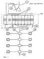
- FIGS. 1 and 2 essentially two systems are used for this purpose, which are shown schematically in FIGS. 1 and 2:
- signals received by the antenna are frequency-demodulated channel-individually after amplification and conversion by units known per se (low-noise amplifier LNA) , Subsequently, the channel-specific frequency demodulated signals are amplitude modulated in a conventional UHF television channel.
- LNA low-noise amplifier
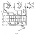
- This system consists of an antenna 1 which receives television signals of one polarity, a converter 2, in particular an LNA / LNB block, and cables 3 which connect the LNA / LNB block to a signal processing unit 400.
- This signal processing unit 400 consists of a plurality of channel-specific FM demodulators / AM modulators 19, a switching element 18, a power supply 17, connecting bridges 7, load components 8. Connected to a single distribution cable (lead) 13 with Auskoppplin 14 and user or antenna sockets 15.
- This system has the disadvantage that it requires a channel-specific FM demodulator / AM modulator 19 for each received satellite channel. If the number of satellite channels to be received is to be increased, the number of necessary FM demodulators / AM modulators must also be increased.
- Each individual FM demodulator / AM modulator, with which both the frequency demodulation and the amplitude modulator is carried out, is relatively complicated in terms of circuitry and therefore expensive.
- the cost of the system of Figure 1 increases significantly as the number of satellite channels to be distributed is increased. Even in relatively small community antenna installations with a small number of users, there are already considerable costs for a few received satellite channels.
- Such a system is known, for example, from EP-A-0 2 888 928, which discloses an apparatus having an internal unit which implements an amplifier and signal converter function.
- This internal unit has a plurality of converters, each with a tuner demodulator and an encoder modulator.
- Such a system is further known from DE-A-40 12 657, wherein in the system converters each having a tunable demodulator and an AM modulator are provided.
- additional distribution cable 13 can be very expensive or possibly excluded in existing systems due to spatial conditions in the buildings where the additional distribution cables would be installed.
- this prior art system requires multiple switching devices 16 to select different distribution cables and to pick up signals transmitted on the selected distribution cable.
- the use of these switching devices, which are connected to the distribution cables, is also associated with the risk that come from the switching devices formed electrical switching pulses on the distribution cables and deteriorate the transmission quality of the signals transmitted there.
- the transponder combination devices then carry those from the satellite transponder processors formed signals zwammen ("frequency mapping").
- the signals are arranged as if they had been transmitted directly from the system's antennas to this node.
- the transponder combination devices power inserter are connected downstream, which are connected on the output side with several distribution cables. The known system is thus designed circuit complex.
- the present invention seeks to provide a system for distributing signals of the type mentioned above, which allows the distribution of a larger number of channels and circuitry is designed in a simple manner, and a corresponding channel-individual converter
- the system according to the invention is characterized by a plurality of vortexes.
- the user is provided with prescribable channels via only one distribution cable, which channels are selected individually from signals originating from one antenna or from a plurality of antennas. With the individual selection of channels, the demand of system users with regard to the reception of predefinable channels can be met individually.
- the channel-specific converter provided according to the invention which convert a predeterminable channel into another channel, but also the system as a whole, are realized in a simple manner in terms of circuit technology.
- the channel-specific converters can be set to any frequency in a predefinable frequency band.
- Individual signals or channels can be superimposed by other signals or channels, with both the 1 superimposed and the superimposed signals are transmitted to the user. Usable for the user, however, are only the overlapping signals.
- the erfindungalice system that a changed demand of system users with regard to the use of predeterminable channels can be flexibly met.
- the system according to the invention can be used, inter alia, in cases in which a single distribution cable has already been laid or in cases where the laying of a further distribution cable would be complicated or precluded due to the same circumstances.
- the system according to the invention in which channels of two polarities or of two or more satellites are transmitted to user sockets via a single distribution cable, has no switching devices on the distribution cable. Thus, no electrical switching pulses are coupled to the distribution cable, so that corresponding disturbances are excluded.
- An advantageous embodiment of the invention is characterized in that the channel-specific converter of the head device are integrated in at least one converter module, wherein the converter module is connected at its input with down converters and at its output to the distribution cable.
- the converter module has at least two converters, wherein the converters in the converter module are connected to one another in chain connection (an input of a first converter module is connected to the input of a second converter module which is adjacent to the first converter module, an output of the first converter module is connected to the first converter module Output of the second converter module connected).
- This chain circuit structure is characterized by the in practice important advantage that not every channel-specific converter is to be connected via a separate cable with a down converter and that, moreover, not every channel-specific converter is to be connected via a separate cable with a mixer or adder , which is upstream of the distribution cable.
- the use of the derailleur structure saves both the separate cables and the cost of installing them.
- the channel-specific converter or its inputs and / or their outputs can be connected to one another by means of connecting bridges known per se.
- the system according to the invention enables the processing and distribution of signals of a plurality of television channels.
- several converter modules in which a variable number of channel-specific converters can be integrated. e.g. connect via a mixer ('9').
- the system according to the invention may comprise a further mixer ("5") with at least two inputs.
- one of the inputs is connected to the output of a converter module, while another input is connected directly to a down converter of an antenna
- This mixer, the output side may be connected via an amplifier with the distribution cable, makes it possible to couple more channels in the distribution cable, and although from first channels or signals that are emitted by satellites and received by satellite dishes. as well as second channels or signals emitted by terrestrial transmitters and received by conventional antennas, as well as first and second signals.
- the channel individual converters may each comprise a microprocessor which controls at least one oscillator.
- the microprocessor makes it possible to detachably connect a converter-read input device to the microprocessor and to input data into the converter or the microprocessor which designate a predefinable input channel frequency and a predefinable output channel frequency.
- the channel-independent converter can be adjusted in a particularly simple manner to a predefinable input frequency and to a predefinable output frequency, by which the frequency conversion of a channel is determined.
- the external converter input device can also be configured as a remote control transmitter.
- the channel-specific converter have an amplifier with controllable gain, wherein a mixer ("5") with at least two inputs signals of different channels of the same frequency are supplied with different signal levels. This makes it easy to superimpose different channels on the distribution cable.
- the signal level difference of at least 15 dB provided according to the invention the overlapping channels in the terminals which can be connected to the user sockets can be represented in good reception quality.
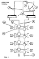
- Block A of the system according to the invention consists of antennas 1 which receive the signals from television channels transmitted via satellites. If the antennas are parabolic antennas, a down converter 2 is arranged in each case at the focal point of an antenna 1, which measures the received signals in a manner known per se from the satellite television reception frequency range of e.g. 10.7 - 12.5 GHz in the intermediate frequency range between 950 MHz and 2050 MHz (commonly referred to as "first intermediate frequency") implement.
- Such down-converters 2 with an amplifier LNA and a channel block converter LNB are known and available on the market.
- Each antenna 1 has. one or two down-converters 2 (or a down-converter with two outputs) depending on whether signals of one or two polarities (horizontal, vertical) per antenna are to be received. If the antenna 1 receives signals of one polarity, a down converter 2 is provided; receives the antenna 1 signals of two polarities, two down converter 2 are provided.
- the down converter 2 are each connected to a cable 3 on the output side.
- one or more cables 3, as shown in FIGS. 3, 4, 5, 6 and 9, lead to the signal processing unit 400 with at least one channel-specific converter 4. It can also be provided that one or more cables 3, as shown in FIGS. 3, 6 and 9, lead to a ("second") mixer 5, which is connected downstream of a channel-specific converter 4 or a converter module 40 with at least one channel-specific converter 4.
- the channel-specific converter 4 of the head device B are preferably integrated in at least one converter module 40, wherein the converter module 40 is connectable at its input via a cable 3 with a down converter (LNA / LNB) 2 and at its output to the distribution cable 13 (coaxial cable).
- the distribution cable 13 is connected to the output of an amplifier 6, which may be the ("second") mixer 5 downstream.
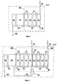
- Each channel-specific converter 4 the circuit design is still explained in detail with reference to Figure 7, has two inputs and two outputs.
- the channel-individual converter 4 a converter module 40 are connected together in such a way that an input (eg EC1 in Figure 7) of a first converter module with the input (eg EC2) of a second (not shown in Figure 7) converter module, which is adjacent to the first converter module is connected. Similarly, an output (e.g., SC1) of the first converter module is connected to the output (e.g., SC2) of the second converter module (ladder circuit).
- This chain circuit structure is characterized by the practically important advantage that not every channel-specific converter 4 is to be connected via a separate cable 3 with a down converter 2 and that moreover not every channel-specific converter 4 via a separate cable with a ("second") Mixer (5) to connect upstream of the distribution cable 13.
- each of the two inputs each e.g. via a respective known connection bridge 7 is connected to an input of an upstream channel-specific converter 4 and to the input of a downstream channel-specific converter 4.
- each of the two outputs is in each case connected, for example. via a respective known connection bridge 7 with an output of an upstream channel-specific converter 4 and with the output of a downstream channel-specific converter 4 is.
- an identical housing is provided for each individual channel converter 4, that is to say a housing of the same spatial dimensions, at which the input and output connections are arranged at the same locations. This allows the use of identical connection bridges 7, with each of which either an electrical connection between two inputs or between two outputs are made.
- an input of a converter 4 (first converter 4 of a converter module 40, which is drawn in each case on the right in FIGS. 4 and 5 in a converter module) with a cable 3 which generates the signals generated by the down converters 2 or in the intermediate frequency range transmits converted signals, is connected.
- An input of a converter 4 (last converter 4 of a converter module 40, which is shown on the left in FIGS. 4 and 5) is connected to a supply source 11 which supplies the converters 4 and an amplifier 12 provided for each signal processing unit 400.
- These channel-specific converter 4 take on the input from the down converters 2 and transmitted via the cable 3 signals or channels in the intermediate frequency range and put the signals or channels in the intermediate frequency range, as will be described with reference to FIGS 9 and 10.
- outputs of the channel-specific converter 4 can be terminated with an ohmic resistor 8 of 75 ohms (see Figure 3, block B, reference numeral 8 below the converters 4; right and left converter modules 40 in Figure 5.
- Figures 6 and 9, reference numeral 8 below the converter 4 These are in particular the output of a (in terms of signal flow) first converter 4 in a first converter module (right converter module in Figure 5) and the output of a (in terms of signal flow) last converter 4 in a last converter module (left converter module in Figure 5).
- a channel is selected and converted from an input frequency in the intermediate frequency range to a predefinable output frequency in the intermediate frequency range.
- a plurality of channel-specific converters 4, at least two, preferably four converters 4 can be integrated in a converter module 40. Two adjacent modules can be combined with one another via a ("first") mixer 9.
- the output of the first mixer 9 is introduced by means of a connecting cable 10 in the arrangement of supply source 11 and amplifier 12.
- the amplified signal is supplied to the second mixer 5.
- the channel-specific converter 4 is preferably configured as follows: On the input side frequency range 950 ... 1950 (or 2050) MHz input level - 50 ... -30 dBm Mirror selection (image frequency rejection) ⁇ 40 dB intermediate frequency 479.5 MHz bandwidth 27 MHz Through input loss ⁇ 1.2 dB On the output side frequency range 950 ... 1950 (or 2050) MHz Max. Output level - 25 ⁇ 5 dBm Output level control range 15 dB bandwidth 27 MHz Through output losses ⁇ 1.2 dB noise level > - 20 dBc
- the feed source 11 is preferably configured as follows: mains voltage 230V ⁇ 15% output voltage 15V / 5V Intermediate frequency loop loss ⁇ 1.2 dB
- the amplifier 12 is preferably configured as follows: bandwidth 950 ... 2050 MHz profit 23 ... 33 dB Max. Output level for two channels 115 dB ⁇ V / 6 dBm
- the first mixer 9 is preferably configured as follows: bandwidth 950 ... 2050 MHz insertion loss ⁇ 4 dB Rejection between inputs 15 dB
- first signals that form a converter module 40 (input E1) as well as second signals that are formed by the downconverters 2 (input E2) as well as third signals that are output from antennas can transmit the signals receive terrestrial transmitter, the second mixer 5 are fed.
- the distribution cable 13 is connected on the output side.
- an amplifier 6 is connected downstream, to the output side, the distribution cable 13 is connected.
- the distribution network C consists of a single distribution cable 13 on which all channels which are FM-modulated are transmitted.
- the distribution cable 13 is formed by a coaxial cable and leads to discharge devices 14 , which decouple the signal to various user sockets 15.
- FIG. 4 shows a signal processing unit 400 with a converter module 400, which consists of four channel-specific converters 4, while FIG. 5 shows a signal processing unit 400 with two converter modules 400, each consisting of four channel-specific converters 4.
- the number of channel-specific converter 4 is equal to the number of channels which are coupled into the distribution cable 13 and transmitted via the discharge devices 14 to the user sockets 15.
- the channel-specific converters can be set to predefinable input frequencies in the intermediate frequency range and to predefinable output frequencies in the intermediate frequency range.
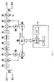
- FIG. 7 shows an embodiment of a channel-specific converter 4.
- Two inputs EC1 and EC2 are electrically connected to each other and to a repeater 42 via a directional coupler 41.
- the inputs EC1 and EC2 are mechanically designed in such a way that known connection bridges (7 in Figure 4) can be used to connect each with an input of an adjacent channel-specific converter. In this way, several channel-specific converters can be integrated into a converter module.
- This form of connection thus consists in that each of the two inputs EC1, EC2 is connected to an input of an upstream channel-specific converter 4 or to the input of a downstream channel-specific converter 4, in each case via a known connection bridge.
- each of the two outputs SC1, SC2 of the converter 4 is in each case connected, for example via a respective known connection bridge, to an output of an upstream channel-specific converter 4 or to the output of a downstream, individual converter 4.
- This connection form has the advantage that distribution devices that would otherwise be downstream of the down converters 2 and connection cables between these distribution devices and channel-specific converters are not needed.
- the amplifier 42 amplifies the supplied signals e.g. in the frequency band from 950 to 2050 MHz.
- the signals are fed to an input-side tracking filter 43.
- This filter is a bandpass filter which is tuned to the selected input channel frequency by means of a voltage formed by a phase-locked loop (PLL) circuit 46.
- the circuit 46 is controlled by a microprocessor (MP) 49.
- MP microprocessor
- a mixer 44 connected downstream of the lag filter 43 is driven by a local oscillator (OL) 45, which in turn is driven by the PLL circuit 46.
- the mixer 44 converts the frequency of the selected channel present at the inputs EC1 and EC2 to a frequency of 479.5 MHz.
- the signal formed by the mixer 44 is fed to a low-pass filter 47 whose cut-off frequency is, for example, 600 MHz.
- a low-pass filter 47 whose cut-off frequency is, for example, 600 MHz.
- the signal is filtered by means of a SAW 50 surface acoustic wave filter, e.g. has a bandwidth of 27 MHz at a center frequency of 479.5 MHz.
- Downstream amplifiers 48 and 51 increase the signal level so that the losses caused by the SAW filter 50 are compensated.
- the mixer 52 connected downstream of the amplifier 51 mixes the signal of the 479.5 MHz frequency signal selected at the input with a signal formed by a local oscillator (OL) 53.
- the local oscillator is controlled by a PLL circuit 54.
- the PLL circuit 54 is also controlled by the microprocessor 49.
- the mixer 52 is followed by an output-side tracking filter 55 which, like the filter 43 is a band-pass filter.
- the filter 55 eliminates the unwanted signals formed in the mixture made by the mixer 52.
- At the output of the filter 55 is then the signal of the frequency converted channel, which is supplied to an amplifier 56.
- the gain of the amplifier 56 is controllable, so that the levels of the frequency converted channel signal can be set to predetermined values (see, for example, in Fig. 8, the channels 1 and 5).
- a downstream directional coupler 57 couples the amplified signal to the outputs SC1, SC2.
- the outputs SC1 and SC2 are designed mechanically in such a way that known connection bridges (7 in FIG. 4) can be used for connection to one output of an adjacent channel-specific converter.
- the converters 4 may include a microprocessor 49 which controls the PLL circuits 46 and 54 and determines the input and output frequency of the channel signal of the converters 4. Furthermore, the microprocessor 49 may control the amplifier 56. To the microprocessor 49 may e.g. an input unit 16 can be connected via a 4-cable bus, via which data of a predefinable input and output frequency and / or control data for the amplifier 56 (signal amplification parameter) can be input to the microprocessor 49.
- the input unit 16 may comprise a controller 162 (in particular a microprocessor MP), a program associated with the controller 162 being e.g. depending on the cut-off frequencies of the respective intermediate frequency range (950 MHz, 2050 MHz), channel bandwidths and channel spacings and signal levels of the channel signals, data corresponding to given technical specifications and input to the microprocessor 49 of the channel-specific converter 4.
- the input unit 16 includes a keyboard 161, the controller 162, and a display 163. On the display, data inputted to the keyboard 161, prompt information, and information indicating the state of the converter after its setting by the input data are displayed.
- the input unit 16 can be designed as a remote control transmitter with a transmitting device which transmits the data to be input to a receiving device which is connected to the microprocessor 49 of the channel-specific converter.
- FIG. 8 shows a second mixer 5, which is also shown in FIG. 3, block B.
- the second mixer 5 has e.g. three inputs E1, E2, E3 and an output S to which the distribution cable 13 is connected.
- the distribution cable 13 is preferably a coaxial cable, but it can also be provided a glass fiber.
- the input E1 is connected directly via a cable to one or more converter modules 40; to the input E2, a cable 3 with a down converter (2 in Figure 3) is connected directly, while the input E3 is connected to a system for receiving terrestrial channels.
- the signals E1, 2, 3, 4, 5 and 6 are input to the input E1 which originate from a satellite, have a bandwidth of 27 MHz, and, as described, have been converted by channel-specific converters in the frequency band between 950 and 2050 MHz.
- the input E2 is supplied with signals of channels 7, 8, 9, 10, 11, 12, 13 and 14 originating from a satellite, having a bandwidth of 27 MHz and, as described, channel-specific converters in the frequency band between 950 and 2050 MHz have been implemented.
- At the entrance E3 are 6 terrestrial TV channels with 8 MHz bandwidth in the frequency band between 47 and 860 MHz.
- the signals of the channels which are present at the input E1 are supplied by the channel-specific converters 4, in which the frequency conversion and the formation of the respective levels with respect to the coupling of the signals via the mixer output S in the distribution cable 13.
- the channels 2, 4 and 6, which are present at the input E1 were so frequency converted in the channel-specific converters 4 that no channels of the same frequencies are present at the input E2.
- the channels 1 and 3 at the input E1 are arranged in frequencies between the non-desired channels 7 and 8 or 9 and 10, which are present at the input E2.
- the signal or Power level of channel 1 is set to a value of at least 15 dB above the corresponding level of channels 7 and 8; and the signal or power level of the channel 3 is set to a value of at least 15 dB above the corresponding level of the channels 9 and 10.
- the channel 5 of the input E1 is arranged in the same frequency as the unwanted channel 12 which is present at the input E2, wherein the signal or power level of the channel 5 is at least 20 dB above the corresponding level of the channel 12.
- the channels in the frequency band from 47 to 860 MHz and the channels 1, 2, 3, 4, 11, 5, 13, 6 and 14 in the frequency band from 950 to 2050 MHz made available to the system user.
- the channels 7, 8, 9, 10 and 12 are transmitted on the distribution cable 13; However, these are superimposed so that they are not made available to the system user.
- the signal level difference of at least 15 dB provided according to the invention the overlapping channels in the terminals which can be connected to the user sockets can be represented in good reception quality.
- FIG. 9 shows an exemplary embodiment of the system according to the invention, which is also shown in FIG. It is assumed that signals of different television channels are received and processed, which come from three satellites of different orbital position with horizontal and vertical position.
- circuit points d, e, f, g, h, i, j, k, I, m, n, and o are indicated.
- FIG. 10 shows the channels at the circuit points d - o shown in FIG. 9.
- the channels 70, 72, 92 are in vertical polarity and the channels 71, 93, 93 are in horizontal polarity.
- the channels 65,..., 69 are in only one polarity.
- Each down converter 2 ( Figure 9) selects one polarity and converts the 10.9-12.5 GHz frequency band to the 950-2050 MHz frequency band such that in each cable 3 at the nodes g, h, i, j, k are the channels that belong to the same satellites and to the same polarity.
- the channels 70, 72,... 92 are present at the node g, at the node h the channels 71, 73,... 93, at the node i the channels 65 - 69, at the node j the channels 49, 51 ... 63, 33 .... 47, 1, 3, ... 31 and at the node k the channels 50, 52 ... 64; 34, 36, ... 48; 2, 4 ... 32.
- converter modules 40 are provided at the circuit points g, h, i, j, wherein the channel-specific converters 4 of the modules 40 are set to the input frequencies of each of the selected channels and to the output frequencies to which the channels are to be arranged. These output frequencies are occupied frequencies of unwanted channels to be overlaid or free frequencies.
- each converter module 40 channels are provided according to the invention, which have a different frequency position relative to the frequency position at the input of the modules.
- the channels 72, 82, 77 and 89 occur at a frequency position different from the frequency position of the channels at the nodes g and h.
- the channels 65, 68, 17 and 41 which come from the circuit points i and j, also in different frequency position.
- all selected channels originating from the nodes g, h, i and j are present in frequency positions differ from the original frequency positions. These channels are introduced via the supply source 11 into the amplifier 12, which amplifies the signal levels of the channels.
- the channels which are present at the node n are mixed with the channels which are present at the node k.
- the channels which are present at node n are superimposed on the channels of the same frequency which are present at node k.
- the channels at node n must have a higher signal level of at least 15, but preferably 18 to 20 dB, above the signal levels of the channels at node k to be superimposed. This difference in level ensures that the channel that overlays another channel is received without interference from the channel that has been overlaid.
- channel 65 is superimposed on channel 60 (compare greater amplitude of 65 versus 60), channel 72 on channel 36, channel 68 on channel 44, channel 82 the channel 2, the channel 77 the channel 6, the channel 17 the channel 12, channel 89 the channel 18 and channel 41 the channel 24th
- signals in particular television signals transmitted by satellites of different channels
- the signals are received in a signaling device A and the received signals of a certain polarity (H, V) converted from a receiving frequency band into signals in an intermediate frequency band.
- the converted into the intermediate frequency band signals are processed and the processed signals are transmitted via a single distribution cable 13 in the intermediate frequency band to user sockets 15.
- individual predeterminable channels in the intermediate frequency band are converted into other channels in the intermediate frequency band.
- first channels are mixed with second channels in the intermediate frequency band and the first and second channels are transmitted via the distribution cable 13.
- different signal levels are formed for two channels of the same frequency converted into the intermediate frequency band, the signal levels of the signals of different channels differing by at least 15 dB.
Landscapes
- Physics & Mathematics (AREA)
- Astronomy & Astrophysics (AREA)
- General Physics & Mathematics (AREA)
- Engineering & Computer Science (AREA)
- Signal Processing (AREA)
- Input Circuits Of Receivers And Coupling Of Receivers And Audio Equipment (AREA)
- Details Of Television Systems (AREA)
- Radio Relay Systems (AREA)
- Two-Way Televisions, Distribution Of Moving Picture Or The Like (AREA)
Claims (14)
- Système pour la distribution de signaux, en particulier un système d'antenne collectif pour la distribution de signaux de télévision de différents canaux, qui sont transmis en particulier par satellites, dans lequel le système comprend:- un poste transmetteur de signaux (A), avec au moins une antenne (1) qui reçoit des signaux, et au moins un convertisseur abaisseur (LNA/LNB 2), qui convertit des signaux reçus avec une polarité déterminée (H, V) dans une gamme de fréquence d'entrée en signaux dans une gamme de fréquence intermédiaire,- un dispositif de tête (B), qui est placé après le poste transmetteur de signaux (A) et qui présente au moins une unité de traitement de signaux (400), qui est raccordée à l'entrée par un câble (3) au convertisseur abaisseur (LNA/LNB 2) et qui peut être raccordée à la sortie à un unique câble de distribution (13), par lequel les signaux traités sont transmis dans la bande de fréquence intermédiaire jusqu'aux prises des utilisateurs (15), dans lequel l'unité de traitement de signaux (400) du dispositif de tête (B) comporte des convertisseurs de canal individuel (4), et dans lequel chaque convertisseur de canal individuel (4) convertit un canal prédéterminable dans la bande de fréquence intermédiaire en un autre canal dans la bande de fréquence intermédiaire,
caractérisé en ce que
le convertisseur de canal individuel (4) présente un amplificateur réglable (56), avec lequel les signaux de télévision introduits dans le convertisseur de canal individuel (4) sont amplifiés, et en ce que le système comprend un dispositif (5) qui superpose les signaux de télévision amplifiés par l'amplificateur réglable (56) du convertisseur de canal individuel (4) à d'autres signaux de télévision, qui sont introduits dans le dispositif (5). - Système suivant la revendication 1, caractérisé en ce que le convertisseur de canal individuel (4) présente un microprocesseur (49), qui commande l'amplificateur (56).
- Système suivant la revendication 2, caractérisé en ce que le microprocesseur (49) commande la conversion d'un canal prédéterminable dans la bande de fréquence intermédiaire en un autre canal dans la bande de fréquence intermédiaire.
- Système suivant l'une des revendications 2 ou 3, caractérisé en ce que le microprocesseur (49) du convertisseur de canal individuel peut être raccordé à un dispositif d'entrée (16) externe au convertisseur, par lequel on peut entrer des données qui définissent les paramètres d'amplification du signal pour la commande de l'amplificateur (56).
- Système suivant l'une des revendications 2, 3 ou 4, caractérisé en ce que le microprocesseur (49) du convertisseur de canal individuel peut être raccordé à un dispositif d'entrée (16) externe au convertisseur, par lequel on peut introduire des données, qui définissent une fréquence de signal d'entrée prédéterminable d'un canal à convertir et une fréquence de signal de sortie prédéterminable d'un canal converti.
- Système suivant l'une des revendications 4 ou 5, caractérisé en ce que le dispositif d'entrée (16) externe au convertisseur présente un organe de commande (162).
- Système suivant l'une quelconque des revendications précédentes, caractérisé en ce que des convertisseurs de canal individuel (4) du dispositif de tête (B) sont intégrés dans au moins un module de convertisseur (40) et en ce que le module de convertisseur (40) peut être à son entrée raccordé aux convertisseurs abaisseurs (LNA/LNB 2) par le câble (3) et à sa sortie au câble de distribution (13).
- Système suivant la revendication 7, caractérisé en ce que le module de convertisseur (40) présente au moins deux convertisseurs de canal individuel (4), et en ce que les convertisseurs de canal individuel (4) sont raccordés l'un à l'autre dans le module de.convertisseur (40) de telle façon qu'une entrée (EC1) d'un premier convertisseur de canal individuel soit raccordée à une entrée (EC2) d'un second convertisseur de canal individuel, qui est voisin du premier convertisseur de canal individuel, et qu'une sortie (SC 1) du premier convertisseur de canal individuel soit raccordée à·une sortie (SC2) du second convertisseur de canal individuel.
- Système suivant la revendication 8, caractérisé en ce que le raccordement des entrées de deux convertisseurs de canal individuel (4) voisins et/ou le raccordement des sorties de deux convertisseurs de canal individuel (4) voisins est réalisé par des ponts de jonction (7).
- Système suivant l'une quelconque des revendications précédentes, caractérisé en ce que le convertisseur de canal individuel (4) présente, à l'entrée et/ou à la sortie, un filtre de poursuite (43, 55).
- Système suivant l'une des revendications 7 - 10, caractérisé en ce que plusieurs modules de convertisseur (40) sont raccordés à un premier mélangeur (9), dont la sortie peut être raccordée au câble de distribution (13) par l'intermédiaire d'une source d'alimentation électrique (11).
- Système suivant l'une quelconque des revendications précédentes, caractérisé en ce que le système présente un second mélangeur (5) avec au moins deux entrées (E1, E2, E3), en ce qu'une des entrées (E1) peut être raccordée à la sortie du module de convertisseur (40), en ce qu'une deuxième entrée (E2, E3) peut être raccordée à un convertisseur abaisseur (LNA/LNB 2) et en ce que le second mélangeur (5) présente une sortie (S), à laquelle le câble de distribution (13) peut être raccordé.
- Système suivant l'une quelconque des revendications précédentes, caractérisé en ce que les niveaux de signal des signaux de télévision surimposés et couverts de différents canaux se différencient d'au moins 15 dB.
- Convertisseur de canal individuel (4) dans un système pour la distribution de signaux, en particulier un système d'antenne collectif pour la distribution de signaux de télévision de canaux différents, qui sont transmis en particulier par des satellites, dans lequel le système présente- un poste transmetteur de signaux (A), avec au moins une antenne (1) qui reçoit des signaux, et au moins un convertisseur abaisseur (LNA/LNB 2), qui convertit des signaux reçus avec une polarité déterminée (H, V) dans une gamme de fréquence d'entrée en signaux dans une gamme de fréquence intermédiaire,- un dispositif de tête (B), qui est placé après le poste transmetteur de signaux (A) et qui présente au moins une unité de traitement de signaux (400), qui est raccordée à l'entrée par un câble (3) au convertisseur abaisseur (LNA/LNB 2) et qui peut être raccordée à la sortie à un unique câble de distribution (13), par lequel les signaux traités sont transmis dans la bande de fréquence intermédiaire jusqu'aux prises des utilisateurs (15), dans lequel l'unité de traitement de signaux (400) du dispositif de tête (B) comporte des convertisseurs de canal individuel (4), et dans lequel chaque convertisseur de canal individuel (4) convertit un canal prédéterminable dans la bande de fréquence intermédiaire en un autre canal dans la bande.de fréquence intermédiaire,
caractérisé en ce que
le convertisseur de canal individuel (4) présente un amplificateur réglable (56), avec lequel des signaux de télévision introduits dans le convertisseur de canal individuel (4) sont amplifiés, et en ce que le système comprend un dispositif (5) qui superpose les signaux de télévision amplifiés par l'amplificateur réglable (56) du convertisseur de canal individuel (4) à d'autres signaux de télévision, qui sont introduits dans le dispositif (5).
Applications Claiming Priority (4)
| Application Number | Priority Date | Filing Date | Title |
|---|---|---|---|
| ES9501160U | 1995-04-27 | ||
| ES9501160U ES1030963Y (es) | 1995-04-27 | 1995-04-27 | Sistema de distribucion de señales de television procedentes de satelite. |
| DE19524201 | 1995-07-03 | ||
| DE19524201 | 1995-07-03 |
Publications (3)
| Publication Number | Publication Date |
|---|---|
| EP0740434A1 EP0740434A1 (fr) | 1996-10-30 |
| EP0740434B1 EP0740434B1 (fr) | 1998-06-10 |
| EP0740434B2 true EP0740434B2 (fr) | 2006-01-11 |
Family
ID=26016505
Family Applications (1)
| Application Number | Title | Priority Date | Filing Date |
|---|---|---|---|
| EP96106739A Expired - Lifetime EP0740434B2 (fr) | 1995-04-27 | 1996-04-29 | Système pour la distribution de programmes de télévision par satellite dans un système d'antenne collectif |
Country Status (4)
| Country | Link |
|---|---|
| EP (1) | EP0740434B2 (fr) |
| DE (2) | DE29607766U1 (fr) |
| DK (1) | DK0740434T4 (fr) |
| ES (1) | ES2122740T5 (fr) |
Families Citing this family (6)
| Publication number | Priority date | Publication date | Assignee | Title |
|---|---|---|---|---|
| DE19749120C2 (de) * | 1997-11-06 | 2002-07-18 | Kathrein Werke Kg | Satelliten-Empfangsanlage sowie zugehöriges Verfahren zum Betrieb einer Antennen-Empfangsanlage |
| ES2148067B1 (es) * | 1998-03-27 | 2001-04-16 | Kathrein Werke Kg | Dispositivo de recepcion de satelites. |
| US7352991B2 (en) * | 2002-03-21 | 2008-04-01 | National Antenna Systems | Satellite signal distribution systems |
| AU2003249544A1 (en) * | 2002-09-24 | 2004-04-19 | Koninklijke Philips Electronics N.V. | Head end having a low noise converter with channel preselecting frequency multiplexor |
| DE102005040012A1 (de) | 2005-08-23 | 2007-03-01 | Christian Schwaiger Gmbh | Verfahren und Vorrichtung zur Konfiguration von n unabhängigen Teilnehmern einer Satelliten-Empfangsanlage |
| DE102013002477B4 (de) * | 2013-02-14 | 2019-01-10 | Tesat-Spacecom Gmbh & Co.Kg | Steuervorrichtung für ein Sendeverstärkerelement |
Family Cites Families (4)
| Publication number | Priority date | Publication date | Assignee | Title |
|---|---|---|---|---|
| JPS5915335A (ja) * | 1982-07-15 | 1984-01-26 | Maspro Denkoh Corp | 衛星放送受信装置 |
| US5073930A (en) * | 1989-10-19 | 1991-12-17 | Green James A | Method and system for receiving and distributing satellite transmitted television signals |
| DE4012657C2 (de) * | 1990-04-20 | 1995-06-01 | Comtec Ag | Gemeinschaftsantennenanlage |
| DE9306499U1 (de) * | 1993-03-19 | 1993-07-08 | Richard Hirschmann GmbH & Co, 7300 Esslingen | Schaltungsanordnung und Vorrichtung zum Betreiben einer Antennenempfangsvorrichtung |
-
1996
- 1996-04-29 DE DE29607766U patent/DE29607766U1/de not_active Expired - Lifetime
- 1996-04-29 EP EP96106739A patent/EP0740434B2/fr not_active Expired - Lifetime
- 1996-04-29 DK DK96106739T patent/DK0740434T4/da active
- 1996-04-29 ES ES96106739T patent/ES2122740T5/es not_active Expired - Lifetime
- 1996-04-29 DE DE59600261T patent/DE59600261D1/de not_active Expired - Lifetime
Also Published As
| Publication number | Publication date |
|---|---|
| DE59600261D1 (de) | 1998-07-16 |
| ES2122740T5 (es) | 2006-09-01 |
| DE29607766U1 (de) | 1996-09-05 |
| EP0740434A1 (fr) | 1996-10-30 |
| ES2122740T3 (es) | 1998-12-16 |
| DK0740434T4 (da) | 2006-03-06 |
| DK0740434T3 (da) | 1999-02-01 |
| EP0740434B1 (fr) | 1998-06-10 |
Similar Documents
| Publication | Publication Date | Title |
|---|---|---|
| DE69819897T2 (de) | Fm videosignalabtragung via verschiedene leitungen | |
| DE19702350B4 (de) | Zentralknoten-Konverter zur Verbindung mit einem Anschluss eines Haus-Netzwerks, das mit einem Koaxialkabel verbunden ist und Verfahren zur Kommunikation | |
| DE2457492C2 (de) | Fernsehverteilungssystem | |
| EP0740434B2 (fr) | Système pour la distribution de programmes de télévision par satellite dans un système d'antenne collectif | |
| DE4327117A1 (de) | Einrichtung für eine Antennenanlage zum Verteilen eines Satellitenempfangssignales | |
| DE19713124C2 (de) | Satelliten-Empfangsanlage | |
| DE69604693T2 (de) | Verbesserungen bei rundfunksignalbehandlung | |
| DE20008239U1 (de) | Multischalter für Satelliten-Zwischenfrequenz-Verteilung | |
| DE4334440A1 (de) | Verfahren und Vorrichtung für die Übertragung von über Antennen empfangenen Signalen | |
| DE19837233B4 (de) | Fernsehsignalgeber | |
| DE10219847A1 (de) | Verfahren sowie Vorrichtung zur Erzeugung zumindest eines Transponders in der Satelliten-Zwischenfrequenz-Ebene | |
| DE69614072T2 (de) | Kabelnetzwerksystem für Videoverteilung und bidirektionale Datenübertragung, mit Freqenzumsetzung im Rückkanal | |
| DE68916751T2 (de) | Verstärkungssystem für Fernverteilung. | |
| DE3808917C2 (fr) | ||
| DE1239350B (de) | Drahtfunksystem fuer Farbfernsehen | |
| EP0157145B1 (fr) | Prise de contact pour antenne | |
| DE4335617C2 (de) | Satellitenempfangsanlage | |
| DE10111441B4 (de) | Schaltungsanordnung für ein HF-Modul in einer Kabel-Set-Top-Box | |
| DE202007017295U1 (de) | Satelliten-Empfangs- und Verteilanlage im Heimbereich mit drahtlosen und drahtgebundenen Übertragungsstrecken und Einspeisung mehrerer Transponder | |
| DE29719893U1 (de) | Fernsteuerbare Kopfstation zum Empfang von Satellitenprogrammen mit Bild- und Tonübertragung über Funk zum jeweiligen Teilnehmer | |
| DE3438505C1 (de) | Anordnung zum wahlweisen Sperren von Fernseh-Sonderkanälen | |
| DE4207306C2 (de) | Empfangsanlage für Satelliten-Fernsehprogramme | |
| DE1265779B (de) | Drahtfunksystem fuer Farbfernsehsignale des Secam-Systems | |
| DE3843451A1 (de) | Satelliten-fernseh- und -tonrundfunkuebertragungssystem | |
| DE3204507C2 (de) | Hochfrequenzübertragungssystem |
Legal Events
| Date | Code | Title | Description |
|---|---|---|---|
| PUAI | Public reference made under article 153(3) epc to a published international application that has entered the european phase |
Free format text: ORIGINAL CODE: 0009012 |
|
| AK | Designated contracting states |
Kind code of ref document: A1 Designated state(s): CH DE DK ES FR GB IT LI PT |
|
| 17P | Request for examination filed |
Effective date: 19961030 |
|
| 17Q | First examination report despatched |
Effective date: 19961220 |
|
| GRAG | Despatch of communication of intention to grant |
Free format text: ORIGINAL CODE: EPIDOS AGRA |
|
| GRAG | Despatch of communication of intention to grant |
Free format text: ORIGINAL CODE: EPIDOS AGRA |
|
| GRAH | Despatch of communication of intention to grant a patent |
Free format text: ORIGINAL CODE: EPIDOS IGRA |
|
| GRAH | Despatch of communication of intention to grant a patent |
Free format text: ORIGINAL CODE: EPIDOS IGRA |
|
| GRAH | Despatch of communication of intention to grant a patent |
Free format text: ORIGINAL CODE: EPIDOS IGRA |
|
| GRAA | (expected) grant |
Free format text: ORIGINAL CODE: 0009210 |
|
| AK | Designated contracting states |
Kind code of ref document: B1 Designated state(s): CH DE DK ES FR GB IT LI PT |
|
| REG | Reference to a national code |
Ref country code: CH Ref legal event code: EP |
|
| REF | Corresponds to: |
Ref document number: 59600261 Country of ref document: DE Date of ref document: 19980716 |
|
| ET | Fr: translation filed | ||
| ITF | It: translation for a ep patent filed | ||
| GBT | Gb: translation of ep patent filed (gb section 77(6)(a)/1977) |
Effective date: 19980716 |
|
| REG | Reference to a national code |
Ref country code: ES Ref legal event code: FG2A Ref document number: 2122740 Country of ref document: ES Kind code of ref document: T3 |
|
| REG | Reference to a national code |
Ref country code: DK Ref legal event code: T3 |
|
| PLBQ | Unpublished change to opponent data |
Free format text: ORIGINAL CODE: EPIDOS OPPO |
|
| PLBI | Opposition filed |
Free format text: ORIGINAL CODE: 0009260 |
|
| PLBF | Reply of patent proprietor to notice(s) of opposition |
Free format text: ORIGINAL CODE: EPIDOS OBSO |
|
| 26 | Opposition filed |
Opponent name: INTERESSENGEMEINSCHAFT FUER RUNDFUNKSCHUTZRECHTE G Effective date: 19990310 |
|
| REG | Reference to a national code |
Ref country code: PT Ref legal event code: SC4A Free format text: AVAILABILITY OF NATIONAL TRANSLATION Effective date: 19990111 |
|
| PLBF | Reply of patent proprietor to notice(s) of opposition |
Free format text: ORIGINAL CODE: EPIDOS OBSO |
|
| PLBF | Reply of patent proprietor to notice(s) of opposition |
Free format text: ORIGINAL CODE: EPIDOS OBSO |
|
| PG25 | Lapsed in a contracting state [announced via postgrant information from national office to epo] |
Ref country code: LI Free format text: LAPSE BECAUSE OF NON-PAYMENT OF DUE FEES Effective date: 20000430 Ref country code: CH Free format text: LAPSE BECAUSE OF NON-PAYMENT OF DUE FEES Effective date: 20000430 |
|
| REG | Reference to a national code |
Ref country code: CH Ref legal event code: PL |
|
| PLBO | Opposition rejected |
Free format text: ORIGINAL CODE: EPIDOS REJO |
|
| APAC | Appeal dossier modified |
Free format text: ORIGINAL CODE: EPIDOS NOAPO |
|
| REG | Reference to a national code |
Ref country code: GB Ref legal event code: IF02 |
|
| APAE | Appeal reference modified |
Free format text: ORIGINAL CODE: EPIDOS REFNO |
|
| APAC | Appeal dossier modified |
Free format text: ORIGINAL CODE: EPIDOS NOAPO |
|
| APBU | Appeal procedure closed |
Free format text: ORIGINAL CODE: EPIDOSNNOA9O |
|
| APBW | Interlocutory revision of appeal recorded |
Free format text: ORIGINAL CODE: EPIDOSNIRAPO |
|
| APAH | Appeal reference modified |
Free format text: ORIGINAL CODE: EPIDOSCREFNO |
|
| PUAH | Patent maintained in amended form |
Free format text: ORIGINAL CODE: 0009272 |
|
| STAA | Information on the status of an ep patent application or granted ep patent |
Free format text: STATUS: PATENT MAINTAINED AS AMENDED |
|
| 27A | Patent maintained in amended form |
Effective date: 20060111 |
|
| AK | Designated contracting states |
Kind code of ref document: B2 Designated state(s): CH DE DK ES FR GB IT LI PT |
|
| REG | Reference to a national code |
Ref country code: DK Ref legal event code: T4 |
|
| GBTA | Gb: translation of amended ep patent filed (gb section 77(6)(b)/1977) | ||
| REG | Reference to a national code |
Ref country code: ES Ref legal event code: DC2A Date of ref document: 20060330 Kind code of ref document: T5 |
|
| ET3 | Fr: translation filed ** decision concerning opposition | ||
| PGFP | Annual fee paid to national office [announced via postgrant information from national office to epo] |
Ref country code: GB Payment date: 20130422 Year of fee payment: 18 Ref country code: DK Payment date: 20130424 Year of fee payment: 18 Ref country code: DE Payment date: 20130430 Year of fee payment: 18 |
|
| PGFP | Annual fee paid to national office [announced via postgrant information from national office to epo] |
Ref country code: FR Payment date: 20130523 Year of fee payment: 18 Ref country code: IT Payment date: 20130427 Year of fee payment: 18 |
|
| PGFP | Annual fee paid to national office [announced via postgrant information from national office to epo] |
Ref country code: ES Payment date: 20140509 Year of fee payment: 19 |
|
| REG | Reference to a national code |
Ref country code: DE Ref legal event code: R119 Ref document number: 59600261 Country of ref document: DE |
|
| REG | Reference to a national code |
Ref country code: DK Ref legal event code: EBP Effective date: 20140430 |
|
| GBPC | Gb: european patent ceased through non-payment of renewal fee |
Effective date: 20140429 |
|
| REG | Reference to a national code |
Ref country code: FR Ref legal event code: ST Effective date: 20141231 |
|
| REG | Reference to a national code |
Ref country code: DE Ref legal event code: R079 Ref document number: 59600261 Country of ref document: DE Free format text: PREVIOUS MAIN CLASS: H04H0001040000 Ipc: H04H0020770000 |
|
| PG25 | Lapsed in a contracting state [announced via postgrant information from national office to epo] |
Ref country code: GB Free format text: LAPSE BECAUSE OF NON-PAYMENT OF DUE FEES Effective date: 20140429 Ref country code: DE Free format text: LAPSE BECAUSE OF NON-PAYMENT OF DUE FEES Effective date: 20141101 |
|
| PG25 | Lapsed in a contracting state [announced via postgrant information from national office to epo] |
Ref country code: FR Free format text: LAPSE BECAUSE OF NON-PAYMENT OF DUE FEES Effective date: 20140430 |
|
| REG | Reference to a national code |
Ref country code: DE Ref legal event code: R119 Ref document number: 59600261 Country of ref document: DE Effective date: 20141101 Ref country code: DE Ref legal event code: R079 Ref document number: 59600261 Country of ref document: DE Free format text: PREVIOUS MAIN CLASS: H04H0001040000 Ipc: H04H0020770000 Effective date: 20150127 |
|
| PG25 | Lapsed in a contracting state [announced via postgrant information from national office to epo] |
Ref country code: IT Free format text: LAPSE BECAUSE OF NON-PAYMENT OF DUE FEES Effective date: 20140429 |
|
| PG25 | Lapsed in a contracting state [announced via postgrant information from national office to epo] |
Ref country code: DK Free format text: LAPSE BECAUSE OF NON-PAYMENT OF DUE FEES Effective date: 20140430 |
|
| PGFP | Annual fee paid to national office [announced via postgrant information from national office to epo] |
Ref country code: PT Payment date: 20150428 Year of fee payment: 20 |
|
| REG | Reference to a national code |
Ref country code: PT Ref legal event code: MM4A Free format text: MAXIMUM VALIDITY LIMIT REACHED Effective date: 20160429 |
|
| REG | Reference to a national code |
Ref country code: ES Ref legal event code: FD2A Effective date: 20160527 |
|
| PG25 | Lapsed in a contracting state [announced via postgrant information from national office to epo] |
Ref country code: ES Free format text: LAPSE BECAUSE OF NON-PAYMENT OF DUE FEES Effective date: 20150430 |
|
| PG25 | Lapsed in a contracting state [announced via postgrant information from national office to epo] |
Ref country code: PT Free format text: LAPSE BECAUSE OF EXPIRATION OF PROTECTION Effective date: 20160505 |