EP0740499B1 - Fixation d'un appareillage sur un rail - Google Patents
Fixation d'un appareillage sur un rail Download PDFInfo
- Publication number
- EP0740499B1 EP0740499B1 EP96106062A EP96106062A EP0740499B1 EP 0740499 B1 EP0740499 B1 EP 0740499B1 EP 96106062 A EP96106062 A EP 96106062A EP 96106062 A EP96106062 A EP 96106062A EP 0740499 B1 EP0740499 B1 EP 0740499B1
- Authority
- EP
- European Patent Office
- Prior art keywords
- fixing
- hat rail
- cooling body
- rail
- board
- Prior art date
- Legal status (The legal status is an assumption and is not a legal conclusion. Google has not performed a legal analysis and makes no representation as to the accuracy of the status listed.)
- Expired - Lifetime
Links
- 238000001816 cooling Methods 0.000 claims 5
- 230000000712 assembly Effects 0.000 description 2
- 238000000429 assembly Methods 0.000 description 2
- 230000006835 compression Effects 0.000 description 2
- 238000007906 compression Methods 0.000 description 2
- 239000012080 ambient air Substances 0.000 description 1
- 238000011161 development Methods 0.000 description 1
- 230000018109 developmental process Effects 0.000 description 1
- 210000003746 feather Anatomy 0.000 description 1
- 239000000725 suspension Substances 0.000 description 1
Images

Classifications
-
- H—ELECTRICITY
- H02—GENERATION; CONVERSION OR DISTRIBUTION OF ELECTRIC POWER
- H02B—BOARDS, SUBSTATIONS OR SWITCHING ARRANGEMENTS FOR THE SUPPLY OR DISTRIBUTION OF ELECTRIC POWER
- H02B1/00—Frameworks, boards, panels, desks, casings; Details of substations or switching arrangements
- H02B1/015—Boards, panels, desks; Parts thereof or accessories therefor
- H02B1/04—Mounting thereon of switches or of other devices in general, the switch or device having, or being without, casing
- H02B1/052—Mounting on rails
-
- H—ELECTRICITY
- H02—GENERATION; CONVERSION OR DISTRIBUTION OF ELECTRIC POWER
- H02B—BOARDS, SUBSTATIONS OR SWITCHING ARRANGEMENTS FOR THE SUPPLY OR DISTRIBUTION OF ELECTRIC POWER
- H02B1/00—Frameworks, boards, panels, desks, casings; Details of substations or switching arrangements
- H02B1/56—Cooling; Ventilation
-
- H—ELECTRICITY
- H05—ELECTRIC TECHNIQUES NOT OTHERWISE PROVIDED FOR
- H05K—PRINTED CIRCUITS; CASINGS OR CONSTRUCTIONAL DETAILS OF ELECTRIC APPARATUS; MANUFACTURE OF ASSEMBLAGES OF ELECTRICAL COMPONENTS
- H05K7/00—Constructional details common to different types of electric apparatus
- H05K7/14—Mounting supporting structure in casing or on frame or rack
- H05K7/1461—Slidable card holders; Card stiffeners; Control or display means therefor
-
- H—ELECTRICITY
- H02—GENERATION; CONVERSION OR DISTRIBUTION OF ELECTRIC POWER
- H02B—BOARDS, SUBSTATIONS OR SWITCHING ARRANGEMENTS FOR THE SUPPLY OR DISTRIBUTION OF ELECTRIC POWER
- H02B1/00—Frameworks, boards, panels, desks, casings; Details of substations or switching arrangements
- H02B1/015—Boards, panels, desks; Parts thereof or accessories therefor
- H02B1/04—Mounting thereon of switches or of other devices in general, the switch or device having, or being without, casing
- H02B1/052—Mounting on rails
- H02B1/0523—Mounting on rails locked into position by a sliding member
Definitions
- the invention relates to the attachment of an assembly to a top-hat rail according to the Preamble of claim 1.
- EP-A-0 547 618 is a holding device for an electronic device with a holding element known.
- Top hat rails are on the rear wall or on a frame of the control cabinet appropriate.
- the board of the assembly has a top-hat rail attachment, by means of a plug on the two legs lying in one plane DIN rail is possible.
- interlocks are also provided, by means of the assembly with easy handling from the top-hat rail again can be removed.
- Electronics modules often also have one or more Heatsink to the loss of heat generated in certain components to the To be able to emit ambient air.
- the heat sinks have a large area and thermally well-coupled with the corresponding components.
- top-hat rail fastenings electronic assemblies A disadvantage of the known embodiments of top-hat rail fastenings electronic assemblies is that on the board itself the top-hat rail attachment is appropriate. In order to achieve a high mechanical strength, the Top hat rail mounting comprise a minimum portion of the board so that this space is no longer available for the assignment of electronic components. Another disadvantage is that the top-hat rail fastening is to be provided as a separate component.
- the object of the present invention is therefore a DIN rail fastening according to the Develop the preamble of claim 1 such that there is an inexpensive Embodiment results.
- the top-hat rail fastening directly on Heatsink of the assembly is attached, so the assembly on the heat sink on the DIN rail is attached.
- the circuit board carrying the electronic components is thus carried over the heat sink.
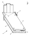
- an electronic assembly 1 consists of a circuit board 2 and a heat sink 3 running flat parallel to the plane of the circuit board 2 indicated that between the board 2 and the heat sink 3 electronic Components are arranged. Is not shown in Fig. 1 that some of the components are connected with their upper side in good thermal contact with the heat sink 3.
- the Heat sink 3 is additionally connected by means of webs 4 to the board 2, so that a high mechanical strength of the assembly 1 is given.
- the edge of the heat sink 3 facing the top hat rail 5 is for a fastening 6 educated.
- On the lower edge of the heat sink 3 is also a manually operated Lock 7 attached, by means of a plugging and removing the Module 1 on the top hat rail 5 is possible.
- Fig. 2 shows a side view of the designed according to the invention DIN rail fastening.
- the profile is shown on an indicated rear wall of a control cabinet mounted top hat rail 5.
- the partially shown heat sink 3 has in the installed state of module 1 at its upper end hook-shaped, the upper, vertical leg of the top-hat rail 5 backing area.
- the lower part of the attachment 6 consists of one formed perpendicular to the lower, vertically extending leg of the top-hat rail 5 Projection which has a pin 8 which is wedge-shaped at its end via a bore linearly movable.
- the end of the pin 8 facing away from the top-hat rail 5 is on hinged to one leg of a rocker 9, which in turn has a swivel connection the lower edge of the heat sink 3.
- a compression spring 10 is arranged, by means of the rocker 9 of the pin 8 in the Is held in the closed position. Pin 8, rocker 9 and compression spring 10 form the lock 7 of the attachment 6.
Landscapes
- Engineering & Computer Science (AREA)
- Power Engineering (AREA)
- Microelectronics & Electronic Packaging (AREA)
- Helmets And Other Head Coverings (AREA)
- Cooling Or The Like Of Electrical Apparatus (AREA)
- Mounting Of Printed Circuit Boards And The Like (AREA)
- Mounting Components In General For Electric Apparatus (AREA)
Claims (4)
- Fixation d'un appareillage électronique sur un profilé chapeau, en particulier dans des armoires de commande de machines d'impression, l'appareillage présentant une platine portant des éléments ainsi qu'un corps de refroidissement,
caractérisée en ce que la fixation (6), pour la suspension au profilé chapeau (5), est agencée sur le corps de refroidissement (3) de l'appareillage (1). - Fixation selon la revendication 1,
caractérisée en ce que la fixation (6) sur le corps de refroidissement (3) comporte un verrouillage (7) pouvant être actionné manuellement, sous forme d'une tige (8), montée de façon linéairement mobile, ayant une extrémité réalisée en forme de coin. - Dispositif selon la revendication 1 ou 2,
caractérisé en ce que le corps de refroidissement (3) avec la fixation (6) est réalisé comme une plaque rectangulaire s'étendant parallèlement à la platine (2). - Fixation selon une des revendications précédentes,
caractérisée en ce que la platine (2) est reliée de plus, par l'intermédiaire de chevilles (4), au corps de refroidissement (3).
Applications Claiming Priority (2)
| Application Number | Priority Date | Filing Date | Title |
|---|---|---|---|
| DE29506766U DE29506766U1 (de) | 1995-04-21 | 1995-04-21 | Befestigung einer Baugruppe an einer Hutschiene |
| DE29506766U | 1995-04-21 |
Publications (2)
| Publication Number | Publication Date |
|---|---|
| EP0740499A1 EP0740499A1 (fr) | 1996-10-30 |
| EP0740499B1 true EP0740499B1 (fr) | 2000-12-20 |
Family
ID=8007135
Family Applications (1)
| Application Number | Title | Priority Date | Filing Date |
|---|---|---|---|
| EP96106062A Expired - Lifetime EP0740499B1 (fr) | 1995-04-21 | 1996-04-18 | Fixation d'un appareillage sur un rail |
Country Status (3)
| Country | Link |
|---|---|
| EP (1) | EP0740499B1 (fr) |
| AT (1) | ATE198251T1 (fr) |
| DE (2) | DE29506766U1 (fr) |
Cited By (2)
| Publication number | Priority date | Publication date | Assignee | Title |
|---|---|---|---|---|
| EP2190277A1 (fr) | 2008-11-24 | 2010-05-26 | Siemens Aktiengesellschaft | Dispositif destiné à la fixation d'un composant électronique |
| WO2023011844A1 (fr) * | 2021-08-06 | 2023-02-09 | Phoenix Contact Gmbh & Co. Kg | Boîtier électronique destiné à être monté sur un rail de support, et système |
Families Citing this family (17)
| Publication number | Priority date | Publication date | Assignee | Title |
|---|---|---|---|---|
| US6563710B1 (en) | 1998-04-01 | 2003-05-13 | Omron Corporation | Electronic device, panel device, and supporting rail |
| DE19851844A1 (de) * | 1998-11-10 | 2000-05-18 | Bernhard Erdl | Gehäuse zur Halterung von elektronischen Baugruppen auf Hutschienen |
| FR2835358B1 (fr) | 2002-01-25 | 2004-09-10 | Schneider Automation | Appareil electrique a fixer sur un profile chapeau |
| DE10243383B3 (de) * | 2002-09-18 | 2004-02-05 | Siemens Ag | Einrichtung zur Befestigung eines Installationsgerätes auf einer Tragschiene |
| EP1578180B1 (fr) * | 2004-03-18 | 2007-10-03 | Murrelektronik GmbH | Bloc d'alimentation |
| DE102008059320B4 (de) * | 2008-11-27 | 2013-11-21 | Knick Elektronische Messgeräte GmbH & Co. KG | Elektronische Geräteanordnung und Kühlkörper hierfür |
| EP2200134B1 (fr) * | 2008-12-02 | 2013-01-30 | Siemens Aktiengesellschaft | Composant doté d'un boîtier pour rail de profilé |
| EP2285199B1 (fr) | 2009-08-11 | 2012-11-21 | Siemens Aktiengesellschaft | Dispositif et composant modulaires |
| GB2521445A (en) * | 2013-12-20 | 2015-06-24 | Control Tech Ltd | Mounting Latch |
| US11178791B2 (en) | 2013-12-30 | 2021-11-16 | Schneider Electric USA, Inc. | Apparatus for increasing heat dissipation capacity of a DIN rail mounted enclosure |
| DE102015104044A1 (de) * | 2015-03-18 | 2016-09-22 | R. Stahl Schaltgeräte GmbH | Modulares System |
| ES2719810T3 (es) * | 2015-11-04 | 2019-07-16 | Selectron Systems Ag | Módulo de sujeción por apriete para la fijación en un raíl de soporte |
| CN106911096B (zh) * | 2017-02-17 | 2018-10-23 | 国网山东省电力公司邹城市供电公司 | 一种多功能通信机柜 |
| DE202019104786U1 (de) * | 2019-08-30 | 2020-12-01 | WAGO Verwaltungsgesellschaft mit beschränkter Haftung | Adapter zur Befestigung einer Vorrichtung auf einer Tragschiene |
| CN112576869A (zh) | 2019-09-27 | 2021-03-30 | 台达电子工业股份有限公司 | 电源模块 |
| TWI707224B (zh) * | 2019-09-27 | 2020-10-11 | 台達電子工業股份有限公司 | 電源模組 |
| BE1028433B1 (de) * | 2020-06-25 | 2022-01-31 | Phoenix Contact Gmbh & Co | Baugruppe mit einem eine Tragstruktur ausbildenden Kühlkörperkernelement |
Family Cites Families (12)
| Publication number | Priority date | Publication date | Assignee | Title |
|---|---|---|---|---|
| DE1815041A1 (de) * | 1968-12-17 | 1970-06-25 | Graesslin Feinwerktech | Schaltungsmodul fuer elektrische Installations-Verteilerschraenke |
| DE7013389U (de) * | 1970-04-11 | 1970-09-24 | Knuerr Kg Elektronik Hans | Variabler lueftereinschub in flachbauweise. |
| FR2120197A5 (fr) * | 1970-08-04 | 1972-08-18 | Lannionnais Electronique | |
| DE2639544C3 (de) * | 1976-09-02 | 1979-09-27 | Licentia Patent-Verwaltungs-Gmbh, 6000 Frankfurt | Anordnung zur Befestigung eines Gehäuses auf einer zweikantigen Tragschiene |
| CH625642A5 (en) * | 1978-01-24 | 1981-09-30 | Friedmann Multidata | Switchboard heater |
| DE3603714A1 (de) * | 1986-02-06 | 1987-08-13 | Murr Elektronik Gmbh | Kuehlkoerper fuer waermeabgebende elektrische bauteile |
| DE8814859U1 (de) * | 1988-11-29 | 1989-04-27 | WSK Werkzeuge und Sondermaschinen GmbH, 6923 Waibstadt | Modul, insbesondere Eingabemodul oder Ausgabemodul oder Schnittstellenmodul |
| DE8815604U1 (de) * | 1988-12-15 | 1989-02-02 | Kobald Electronic Geräte GmbH, Wien | Kleingerätegehäuse für Tragschienenschnappmontage |
| DE3922551C2 (de) * | 1989-07-08 | 1996-06-20 | Geyer Ag | Vorrichtung zur Befestigung eines elektrischen Schaltgerätes |
| AT398678B (de) * | 1991-12-19 | 1995-01-25 | Siemens Ag Oesterreich | Haltevorrichtung für ein elektronisches gerät mit einem halteelement |
| DE9210221U1 (de) * | 1992-07-30 | 1992-10-01 | Krumpe, Alfred, Dipl.-Ing., 8031 Seefeld | Aufbauprinzip für Geräte der Leistungselektronik mit kompakten Gehäusen, z.B. für Normschienen |
| DE9312842U1 (de) * | 1993-08-27 | 1993-12-23 | Elan Schaltelemente GmbH, 35435 Wettenberg | Elektrische Baugruppe |
-
1995
- 1995-04-21 DE DE29506766U patent/DE29506766U1/de not_active Expired - Lifetime
-
1996
- 1996-04-18 EP EP96106062A patent/EP0740499B1/fr not_active Expired - Lifetime
- 1996-04-18 AT AT96106062T patent/ATE198251T1/de not_active IP Right Cessation
- 1996-04-18 DE DE59606226T patent/DE59606226D1/de not_active Expired - Fee Related
Cited By (2)
| Publication number | Priority date | Publication date | Assignee | Title |
|---|---|---|---|---|
| EP2190277A1 (fr) | 2008-11-24 | 2010-05-26 | Siemens Aktiengesellschaft | Dispositif destiné à la fixation d'un composant électronique |
| WO2023011844A1 (fr) * | 2021-08-06 | 2023-02-09 | Phoenix Contact Gmbh & Co. Kg | Boîtier électronique destiné à être monté sur un rail de support, et système |
Also Published As
| Publication number | Publication date |
|---|---|
| ATE198251T1 (de) | 2001-01-15 |
| DE59606226D1 (de) | 2001-01-25 |
| DE29506766U1 (de) | 1995-06-22 |
| EP0740499A1 (fr) | 1996-10-30 |
Similar Documents
| Publication | Publication Date | Title |
|---|---|---|
| EP0740499A1 (fr) | Fixation d'un appareillage sur un rail | |
| DE60032595T2 (de) | Befestigungsvorrichtung zur befestigung von modulen auf einer schiene | |
| EP0642197B1 (fr) | Support d'appareils pour appareils d'installation électrique | |
| EP0776077A3 (fr) | Dispositif pour le montage d'accessoires sur des rails DIN | |
| DE4206073A1 (de) | Grundeinheit fuer eine steuerung | |
| DE4000548A1 (de) | Steckerleiste | |
| EP1314345B1 (fr) | Levier d'actionnement a element d'affichage | |
| EP0465883B1 (fr) | Borne de connexion pour fixation sur un rail conducteur | |
| EP1354384A1 (fr) | Adaptateur de profile support | |
| DE19727454B4 (de) | Anordnung zur lösbaren Befestigung an einer Schiene | |
| DE9202815U1 (de) | Vorrichtung zur Befestigung von Schaltgeräten | |
| DE29602426U1 (de) | Gehäuse für elektrische und elektronische Bauelemente, Baugruppen und/oder Baugruppenträger | |
| DE2648661B2 (de) | Haltevorrichtung für mit einem Stecker versehbare Leiterplatten o.dgl. Bauteile elektromechanischer Bauelemente | |
| DE102006009215B3 (de) | Computergehäuse | |
| DE29922557U1 (de) | Betätigungselement für Flachbaugrupen mit Ein- und/oder Aushebelstück, Frontelement für Flachbaugruppen, Baugruppenträger zur Aufnahme von Flachbaugruppen | |
| EP1376793B1 (fr) | Adaptateur pour l'installation de blocs de connection dans des dispositifs de distribution électrique | |
| AT397900B (de) | Auf genormte hutschiene aufschnappbarer träger für leiterplatten | |
| EP0446575A2 (fr) | Plaque de montage, en particulier pour boîtiers pour la technique des télécommunications et du traitement des données | |
| EP0031181A2 (fr) | Dispositif d'insertion et d'extraction de cartes à circuits imprimés | |
| CH667959A5 (en) | Housing frame for electronic rack mounted circuit boards - has hinged front carrier unit that retains modules and provides handles for carrying | |
| DE3047089A1 (de) | Verriegelungsvorrichtung fuer baugruppen | |
| DE4312989C1 (de) | Baugruppenträger | |
| DE3434640A1 (de) | Einrichtung zur befestigung von platten, z.b. leiterplatten an einem traeger | |
| DE102024114051A1 (de) | Befestigungsformelement zum Befestigen einer Tragschiene an einer Montagebasis | |
| DE102024111474A1 (de) | Elektronikmodul mit einem Elektronikgehäuse mit einem Montagefuß |
Legal Events
| Date | Code | Title | Description |
|---|---|---|---|
| PUAI | Public reference made under article 153(3) epc to a published international application that has entered the european phase |
Free format text: ORIGINAL CODE: 0009012 |
|
| 17P | Request for examination filed |
Effective date: 19960503 |
|
| AK | Designated contracting states |
Kind code of ref document: A1 Designated state(s): AT CH DE FR GB IT LI |
|
| GRAG | Despatch of communication of intention to grant |
Free format text: ORIGINAL CODE: EPIDOS AGRA |
|
| GRAG | Despatch of communication of intention to grant |
Free format text: ORIGINAL CODE: EPIDOS AGRA |
|
| GRAH | Despatch of communication of intention to grant a patent |
Free format text: ORIGINAL CODE: EPIDOS IGRA |
|
| 17Q | First examination report despatched |
Effective date: 20000529 |
|
| GRAH | Despatch of communication of intention to grant a patent |
Free format text: ORIGINAL CODE: EPIDOS IGRA |
|
| GRAA | (expected) grant |
Free format text: ORIGINAL CODE: 0009210 |
|
| AK | Designated contracting states |
Kind code of ref document: B1 Designated state(s): AT CH DE FR GB IT LI |
|
| PG25 | Lapsed in a contracting state [announced via postgrant information from national office to epo] |
Ref country code: IT Free format text: LAPSE BECAUSE OF FAILURE TO SUBMIT A TRANSLATION OF THE DESCRIPTION OR TO PAY THE FEE WITHIN THE PRE;WARNING: LAPSES OF ITALIAN PATENTS WITH EFFECTIVE DATE BEFORE 2007 MAY HAVE OCCURRED AT ANY TIME BEFORE 2007. THE CORRECT EFFECTIVE DATE MAY BE DIFFERENT FROM THE ONE RECORDED.SCRIBED TIME-LIMIT Effective date: 20001220 |
|
| REF | Corresponds to: |
Ref document number: 198251 Country of ref document: AT Date of ref document: 20010115 Kind code of ref document: T |
|
| ET | Fr: translation filed | ||
| REG | Reference to a national code |
Ref country code: CH Ref legal event code: EP |
|
| REF | Corresponds to: |
Ref document number: 59606226 Country of ref document: DE Date of ref document: 20010125 |
|
| GBT | Gb: translation of ep patent filed (gb section 77(6)(a)/1977) |
Effective date: 20010409 |
|
| PG25 | Lapsed in a contracting state [announced via postgrant information from national office to epo] |
Ref country code: LI Free format text: LAPSE BECAUSE OF NON-PAYMENT OF DUE FEES Effective date: 20010517 Ref country code: CH Free format text: LAPSE BECAUSE OF NON-PAYMENT OF DUE FEES Effective date: 20010517 |
|
| PLBE | No opposition filed within time limit |
Free format text: ORIGINAL CODE: 0009261 |
|
| STAA | Information on the status of an ep patent application or granted ep patent |
Free format text: STATUS: NO OPPOSITION FILED WITHIN TIME LIMIT |
|
| 26N | No opposition filed | ||
| REG | Reference to a national code |
Ref country code: CH Ref legal event code: PL |
|
| REG | Reference to a national code |
Ref country code: GB Ref legal event code: IF02 |
|
| PGFP | Annual fee paid to national office [announced via postgrant information from national office to epo] |
Ref country code: GB Payment date: 20030326 Year of fee payment: 8 |
|
| PGFP | Annual fee paid to national office [announced via postgrant information from national office to epo] |
Ref country code: AT Payment date: 20030403 Year of fee payment: 8 |
|
| PGFP | Annual fee paid to national office [announced via postgrant information from national office to epo] |
Ref country code: FR Payment date: 20030408 Year of fee payment: 8 |
|
| PG25 | Lapsed in a contracting state [announced via postgrant information from national office to epo] |
Ref country code: GB Free format text: LAPSE BECAUSE OF NON-PAYMENT OF DUE FEES Effective date: 20040418 Ref country code: AT Free format text: LAPSE BECAUSE OF NON-PAYMENT OF DUE FEES Effective date: 20040418 |
|
| GBPC | Gb: european patent ceased through non-payment of renewal fee |
Effective date: 20040418 |
|
| PG25 | Lapsed in a contracting state [announced via postgrant information from national office to epo] |
Ref country code: FR Free format text: LAPSE BECAUSE OF NON-PAYMENT OF DUE FEES Effective date: 20041231 |
|
| REG | Reference to a national code |
Ref country code: FR Ref legal event code: ST |
|
| PGFP | Annual fee paid to national office [announced via postgrant information from national office to epo] |
Ref country code: DE Payment date: 20070423 Year of fee payment: 12 |
|
| PG25 | Lapsed in a contracting state [announced via postgrant information from national office to epo] |
Ref country code: DE Free format text: LAPSE BECAUSE OF NON-PAYMENT OF DUE FEES Effective date: 20081101 |