EP0740532B1 - Trokarsystem - Google Patents
Trokarsystem Download PDFInfo
- Publication number
- EP0740532B1 EP0740532B1 EP95905551A EP95905551A EP0740532B1 EP 0740532 B1 EP0740532 B1 EP 0740532B1 EP 95905551 A EP95905551 A EP 95905551A EP 95905551 A EP95905551 A EP 95905551A EP 0740532 B1 EP0740532 B1 EP 0740532B1
- Authority
- EP
- European Patent Office
- Prior art keywords
- trocar
- tube
- trocar tube
- valve housing
- plunger
- Prior art date
- Legal status (The legal status is an assumption and is not a legal conclusion. Google has not performed a legal analysis and makes no representation as to the accuracy of the status listed.)
- Expired - Lifetime
Links
- 239000000463 material Substances 0.000 claims abstract description 13
- 230000004323 axial length Effects 0.000 claims description 7
- 239000013013 elastic material Substances 0.000 claims description 7
- 230000014759 maintenance of location Effects 0.000 claims description 3
- 230000002093 peripheral effect Effects 0.000 claims description 2
- 238000004804 winding Methods 0.000 claims 2
- 238000007789 sealing Methods 0.000 description 20
- 239000004033 plastic Substances 0.000 description 4
- 229920003023 plastic Polymers 0.000 description 4
- 230000003716 rejuvenation Effects 0.000 description 3
- 239000000565 sealant Substances 0.000 description 3
- 238000004873 anchoring Methods 0.000 description 2
- 238000005452 bending Methods 0.000 description 2
- 239000003795 chemical substances by application Substances 0.000 description 2
- 230000006835 compression Effects 0.000 description 2
- 238000007906 compression Methods 0.000 description 2
- 230000037431 insertion Effects 0.000 description 2
- 238000003780 insertion Methods 0.000 description 2
- -1 PTFG Polymers 0.000 description 1
- 210000003815 abdominal wall Anatomy 0.000 description 1
- 230000002950 deficient Effects 0.000 description 1
- 230000003670 easy-to-clean Effects 0.000 description 1
- 239000002184 metal Substances 0.000 description 1
- 229920002635 polyurethane Polymers 0.000 description 1
- 239000004814 polyurethane Substances 0.000 description 1
- 230000036316 preload Effects 0.000 description 1
- 230000000452 restraining effect Effects 0.000 description 1
- 230000006641 stabilisation Effects 0.000 description 1
- 238000011105 stabilization Methods 0.000 description 1
- 229910001220 stainless steel Inorganic materials 0.000 description 1
- 239000010935 stainless steel Substances 0.000 description 1
- 238000001356 surgical procedure Methods 0.000 description 1
- 230000000472 traumatic effect Effects 0.000 description 1
Images
Classifications
-
- A—HUMAN NECESSITIES
- A61—MEDICAL OR VETERINARY SCIENCE; HYGIENE
- A61B—DIAGNOSIS; SURGERY; IDENTIFICATION
- A61B17/00—Surgical instruments, devices or methods
- A61B17/34—Trocars; Puncturing needles
- A61B17/3417—Details of tips or shafts, e.g. grooves, expandable, bendable; Multiple coaxial sliding cannulas, e.g. for dilating
- A61B17/3421—Cannulas
-
- A—HUMAN NECESSITIES
- A61—MEDICAL OR VETERINARY SCIENCE; HYGIENE
- A61B—DIAGNOSIS; SURGERY; IDENTIFICATION
- A61B17/00—Surgical instruments, devices or methods
- A61B17/34—Trocars; Puncturing needles
- A61B17/3417—Details of tips or shafts, e.g. grooves, expandable, bendable; Multiple coaxial sliding cannulas, e.g. for dilating
- A61B17/3421—Cannulas
- A61B17/3439—Cannulas with means for changing the inner diameter of the cannula, e.g. expandable
-
- A—HUMAN NECESSITIES
- A61—MEDICAL OR VETERINARY SCIENCE; HYGIENE
- A61B—DIAGNOSIS; SURGERY; IDENTIFICATION
- A61B17/00—Surgical instruments, devices or methods
- A61B17/34—Trocars; Puncturing needles
- A61B17/3498—Valves therefor, e.g. flapper valves, slide valves
-
- A—HUMAN NECESSITIES
- A61—MEDICAL OR VETERINARY SCIENCE; HYGIENE
- A61B—DIAGNOSIS; SURGERY; IDENTIFICATION
- A61B17/00—Surgical instruments, devices or methods
- A61B17/28—Surgical forceps
- A61B17/29—Forceps for use in minimally invasive surgery
- A61B2017/2901—Details of shaft
- A61B2017/2905—Details of shaft flexible
-
- A—HUMAN NECESSITIES
- A61—MEDICAL OR VETERINARY SCIENCE; HYGIENE
- A61B—DIAGNOSIS; SURGERY; IDENTIFICATION
- A61B90/00—Instruments, implements or accessories specially adapted for surgery or diagnosis and not covered by any of the groups A61B1/00 - A61B50/00, e.g. for luxation treatment or for protecting wound edges
- A61B90/08—Accessories or related features not otherwise provided for
- A61B2090/0813—Accessories designed for easy sterilising, i.e. re-usable
Definitions
- the invention is based on a trocar system that one Lumen-limiting flexible trocar tube, a trocar tappet and has a valve mechanism on the patient pioneering end of the trocar tube is formed and through its valve housing the trocar tappet into the Trocar tube is insertable.
- Such trocar systems are known from DE-OS 43 12 147. These trocar systems include an obturator stainless steel or other rigid material and one Cannula made of a plastic such as PTFG, polyurethane or PVC.
- the cannula made of such a plastic has a proximal open end and a distal open end End up and is pliable to introduce an arcuate curved surgical tool through the cannula into the To allow body cavity without its inside diameter must be enlarged.
- the trocar system according to DE-OS 43 12 147 is fundamental for the introduction of a curved surgical instrument in a body cavity.
- the trocar tube in the tissue can also possibly moved back and forth or moved. Therefore a Trocar tube especially when introducing heavily curved Instruments that are securely anchored in the tissue.
- the invention is therefore based on the object, known to develop flexible trocar systems in such a way that the anchoring of the trocar tube in the tissue is improved and that too the introduction of more curved instruments in the Trocar tube is safely possible.
- the Trocar tube is stretchable with respect to the axial length that the The trocar tube has a taper at the patient end, which is a circular step or a conical one Section at the tip of the trocar pestle embraces positively.
- the taper is designed so that it is narrow in the tip area of the trocar tappet can fit positively.
- the taper encompasses a circular step or one conical section at the tip of the Trocar tappet.
- the positive connection can be axial forces acting against the direction of the feed of the trocar tube.
- Averted from the patient A collar is formed at the end of the trocar tube, in the valve housing is storable.
- the federal government can use deposits in the federal government material or stabilized via support rings and is in Valve housing held axially immovable. In further embodiments the invention, it would also be possible that the Trocar tube is rotatably held in the valve housing.
- a trocar trained according to this technical teaching has the advantage that the trocar tube defines the trocar tappet can be biased. An inadmissible overstretching of the Trocar tube can thus be excluded. Is the trocar tube biased, it can, for example, via the Valve housing can be detachably connected to the trocar tappet.
- the trocar tube is supported on the one hand by the circular one Level of the trocar ram and on the other hand the Trocar tube preferred over its machine-side end on Trocar pus attached. Is the trocar stem thinner as its tip, the trocar tappet can easily be in the trocar tube slide until the tip of the trocar plunger is positive engages in the taper of the trocar tube.
- Trocars Another advantage of a trained according to the invention Trocars is that the length of the trocar tube the cross section of the trocar tube is reduced. After removal of the trocar tappet pulls out of the trocar tube this together again and thus shortens. Enlarged the cross section of the trocar tube. This cross-sectional enlargement causes the trocar tube to be firmer is anchored in the tissue than before. This will on the one hand causes the traumatic effect of the tube in the tissue is reduced and that on the other hand the attachment or anchorage of the trocar tube in the tissue increased significantly is so that the slipping of the trocar tube during the Surgery is prevented.
- Another advantage is that the better Anchoring of the trocar tube in the tissue also ensured is that no gas can accidentally escape from the body cavity can.
- the trocar system according to the invention also has the essential Advantage that the trocar tube even with large ones on the trocar tube sleeve tip acting axially directed forces without compression is led.
- the trocar tappet takes the trocar tube with it without the trocar tube against the placement feed direction could move.
- the trocar tube is made of an elastic tubular material manufactured, which is suitable for the radial forces required To include scope, so can easily Gas tightness both in the stem area and in the valve area with the rubber-elastic sealing washer be guaranteed and the risk of undesirable lumen narrowing along the trocar tube is counteracted safely. Care should be taken when selecting the shaft material that the trocar tube with the trocar tappet removed has a bending behavior that is also strongly curved Can accommodate instruments and curved during the introduction Instruments with a constant lumen an impermissible Prevents kinking.
- Trocar tube as a spiral covered with elastic material formed, the individual spiral turns spaced apart are and the elastic material closes the Space between the individual spiral turns over the seen axial length of the trocar tube.
- the coil can be designed as a wire coil spring of an elastic material with good sliding properties is encased.
- the wire coil reliably prevents the lumen is not inadmissible when bending the trocar tube is changed and an instrument does not happen difficult.
- the helix can be designed as a ring that like the rest of the wire insert along the entire trocar tube with a tissue compatible elastic material is encased.
- the wire insert can have any structure and does not necessarily have to be designed as a helical spring.
- the trocar tappet a greater axial length than the trocar tube at rest on.
- the trocar tube before placement can be cut. Is the trocar tappet in cross section seen smaller in diameter than the trocar tube, the trocar tube can become axial Taper elongation in diameter. This makes insertion easier of the trocar tappet into a layer of tissue because at reduced total diameter the puncture resistance also is reduced.
- valve mechanism is held in the valve housing which has at least one elastic seal that the trocar tappet grips gas-tight in the trocar tube and the lumen seals gas-tight when the trocar tappet is removed.
- sealing washers are used as a valve mechanism one or more sealing washers used, is a low axial height in Valve area possible and the sealing area has a additional flexibility. Stronger to heavily curved surgical instruments of any kind can be given Push the lumen through the trocar tube without problems, because the sealing washer or the lumen in Do not reduce or block the area of the valve mechanism. Under pressure, sealing washers can give way and they can also quickly if required without increased costs be replaced.
- valve housing dismantled.
- the trocar tube is held in the valve housing.
- the collar lies on the case back on the inside of the Valve housing on. Support rings or Connect the sealing washers.
- the valve body is over closed a housing cover that the sealing washer or sealing washers on the collar of the tube shaft presses.
- the housing cover on the valve housing can be clamped be kept.
- the valve housing is about loosening the clips easy to disassemble and clean. Defective items can be replaced quickly.
- a sealant can use suitable sealing washers in the valve housing or sealing rings are used.
- the trocar tube has on the outer peripheral surface, preferably in the area of end of the patient, retention agents, such as Tabs, wings, ring-shaped elements or one inflatable cuff.
- retention agents such as Tabs, wings, ring-shaped elements or one inflatable cuff.
- the trocar system according to the invention can be flexible Trocar tubes from piercing to final placement on Support the trocar plunger tip area securely and an impermissible one Compression of the trocar tube material is avoided.
- About the sealant (washers and / or rings) is a low height in the area of the valve mechanism. This also allows the insertion of instruments with larger ones Radii of curvature.
- the trocar tube according to the invention is centered during placement and after removing the Trocar ram fixed automatically. A defined preload of the trocar tube and the attachment to the trocar tappet can be prepared before use. An impermissible Overextension of the trocar tube in the axial direction must be avoided.
- sealing washers in the valve housing make the trocar tappet gas-tight include. Sealing washers have the advantage that the lumen automatically when the trocar tappet is withdrawn can be sealed sufficiently gas-tight.
- Fig. 1 shows at 10 a trocar system, which consists of a Trocar tube 11, a trocar tappet 12 and a valve housing 13 composed, which is connected to the trocar tube 11 is.
- a trocar system which consists of a Trocar tube 11, a trocar tappet 12 and a valve housing 13 composed, which is connected to the trocar tube 11 is.
- a circular shoulder 15 is formed, to which a conical Mandrel 16 connects.
- a shaft section 17 of the trocar tappet 12, which extends from the tip area 14 to one Handle 18 extends has a smaller diameter than the tip area 14.
- At Trokarstössel 12 is the top area 14 formed opposite the handle 18 on that of the trocar tappet 12 and through the valve housing 13 can be inserted into the trocar tube 11.
- a sealing cap 20 is formed on the valve housing 13, which is made of a rubber-elastic material and in the valve housing 13 and in the trocar tube shaft inserted gripping trocar tappet 12 can encompass.
- the trocar tube 11 is tapered at the patient end 21 educated.
- the trocar tube 11 is made from a helix 22 which is covered by a rubber-elastic plastic material. The individual spiral turns are spaced apart and the gaps between the spiral turns are also filled in by the plastic material. The trocar tube 11 is bendable in the direction of the arrow 23 and it is also in the direction of the arrow 24 stretchy.
- the coil 22 is preferably a metal coil.
- a trocar tappet 12 is inserted into the trocar tube 11, which is longer than the trocar tube 11 with the valve housing 13, the trocar tappet 12 can only so far be inserted into the trocar tube 11 until the circular Step or shoulder 15 of the trocar tappet 12 in a form-fitting manner in the taper at the patient end 21 of the Trocar tube 11 engages.
- the trocar tappet 12 continues pushed in the direction of arrow 24 with a fixed valve housing 13, the trocar tube 11 expands in the direction of the arrow 24.
- the valve housing 13 is constructed to be dismantled and is about Brackets 25 held together. In Figure 1 there are two brackets 25 shown.
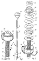
- FIG. 2 shows a trocar tube 11 and a valve housing 13, that opened and arranged in the valve housing 13 Individual parts is disassembled.
- the Trocar tube 11 on the taper at the patient end 21 can be inserted.
- a sealing ring 29 is placed on which the first sealing washer 30 and the second sealing washer Support 32.
- the sealing washers 30, 31 are with Provide slots 30 ', 31' so that the valve housing is closed 13 of the trocar tappet 12 through the valve housing 13 can be passed through.
- the slots 30 ', 31' can lying on top of each other rotated by 90 °, for example be arranged.
- the valve housing 13 is via a housing cover 32 closable, the clamps 25 on the built-in parts in the valve housing 13 is pressed.
- a tubular shoulder 33 is formed on which the rubber-elastic sealing cap 20 can be attached.
- Retaining means can be on the outer surface of the trocar tube 11 be provided, the trocar tube 11 stable in position Fix tissue. Tabs are suitable as restraining devices or annular frets that form when the trocar tube is pulled back 11 open from the tissue and form a counterforce. If the force when retracting the trocar tube 11 greater than the maximum counterforce, so those addressed here Restraint in the pull-out direction of the trocar tube 11 tip over and lie on the outer surface. Is overcome the maximum locking force of the restraint, so can the trocar tube 11 without further increased effort be removed from the tissue. Suitable as a restraint also attached to the outer surface of the trocar tube Coils or an inflatable cuff. The restraint are preferably below the valve housing 13 and in a certain distance from it over a certain axial length trained on the trocar tube shaft.
- a trocar system 10 is composed of a trocar tube 11, a Trocar tappet 12 and a valve housing 13 together, the end of the trocar tube 11 pointing away from the patient is trained.
- the trocar tube 11 is made of a flexible Material made that is stabilized by a coil 22 is.
- the trocar tube 11 has at the patient end 21 a rejuvenation based on a circular shoulder 15 with the trocar plunger 12 inserted into the trocar tube 11 can support.
- the trocar tube 11 is in the direction of the arrow 23 bendable and stretchable in the direction of arrow 24.
Landscapes
- Health & Medical Sciences (AREA)
- Surgery (AREA)
- Life Sciences & Earth Sciences (AREA)
- Medical Informatics (AREA)
- Animal Behavior & Ethology (AREA)
- Engineering & Computer Science (AREA)
- Biomedical Technology (AREA)
- Heart & Thoracic Surgery (AREA)
- Pathology (AREA)
- Molecular Biology (AREA)
- Nuclear Medicine, Radiotherapy & Molecular Imaging (AREA)
- General Health & Medical Sciences (AREA)
- Public Health (AREA)
- Veterinary Medicine (AREA)
- Surgical Instruments (AREA)
- Endoscopes (AREA)
- Media Introduction/Drainage Providing Device (AREA)
- Magnetic Resonance Imaging Apparatus (AREA)
Description
- Fig. 1
- ein erfindungsgemäßes Trokarsystem bestehend aus einem Trokartubus mit einem Ventilgehäuse und einem Trokarstössel;
- Fig. 2
- einen Trokartubus mit geöffnetem Ventilgehäuse, das die in der Figur gezeigten Einzelteile aufnimmt.
Claims (8)
- Trokarsystem, das einen ein Lumen begrenzenden, biegbaren Trokartubus (11), einen Trokarstössel (12) und einen Ventilmechanismus (13) aufweist, der am vom Patienten wegweisenden Ende des Trokartubus (11) ausgebildet ist und durch dessen Ventilgehäuse (13) hindurch der Trokarstössel in den Trokartubus (11) einführbar ist, dadurch gekennzeichnet, daß der Trokartubus (11) bezüglich der axialen Länge dehnbar ist, daß der Trokartubus (11) am patientenseitigen Ende eine Verjüngung (21) aufweist, die eine zirkuläre Stufe oder einen konusförmig verlaufenden Abschnitt an der Spitze des Trokarstössels (12) formschlüssig umgreift.
- Trokarsystem nach Anspruch 1, dadurch gekennzeichnet, daß der Trokartubus (11) als mit elastischem Material ummantelte Wendel (22) ausgebildet ist.
- Trokarsystem nach Anspruch 2, dadurch gekennzeichnet, daß einzelne Wendelwindungen der Wendel (22) von einander beabstandet sind und daß das elastische Material den Zwischenraum zwischen den Wendelwindungen über die axiale Länge des Trokartubus (11) verschließt.
- Trokarsystem nach einem der Ansprüche 1 bis 3, dadurch gekennzeichnet, daß der Trokarstössel (12) eine größere axiale Länge als der Trokartubus (11) im Ruhezustand aufweist.
- Trokarsystem nach einem der Ansprüche 1 bis 4, dadurch gekennzeichnet, daß der Ventilmechanismus in dem Ventilgehäuse (13) gehalten ist, das mindestens eine elastische Dichtung (30, 31) aufweist, die den Trokarstössel (12) im Trokartubus (11) gasdicht umgreift und das Lumen bei entferntem Trokarstössel (12) gasdicht verschließt.
- Trokarsystem nach einem der Ansprüche 1 bis 5, dadurch gekennzeichnet, daß das Ventilgehäuse (13) zerlegbar aufgebaut ist.
- Trokarsystem nach einem der Ansprüche 1 bis 6, dadurch gekennzeichnet, daß alle Einzelkomponenten des Trokarsystems aus reinigbaren und sterilisierbaren Materialien gefertigt sind.
- Trokarsystem nach einem der Ansprüche 1 bis 7, dadurch gekennzeichnet, daß der Trokartubus (11) an der Außenumfangsoberfläche, bevorzugt im Bereich des vom Patienten wegweisenden Endes, Retentionsmittel, wie Laschen, Flügel, ringförmige Elemente oder eine aufblasbare Manschette, ausweist.
Applications Claiming Priority (3)
| Application Number | Priority Date | Filing Date | Title |
|---|---|---|---|
| DE4401237A DE4401237C2 (de) | 1994-01-18 | 1994-01-18 | Trokarvorrichtung |
| DE4401237 | 1994-01-18 | ||
| PCT/DE1995/000058 WO1995019146A1 (de) | 1994-01-18 | 1995-01-16 | Trokarsystem |
Publications (2)
| Publication Number | Publication Date |
|---|---|
| EP0740532A1 EP0740532A1 (de) | 1996-11-06 |
| EP0740532B1 true EP0740532B1 (de) | 1998-07-22 |
Family
ID=6508107
Family Applications (1)
| Application Number | Title | Priority Date | Filing Date |
|---|---|---|---|
| EP95905551A Expired - Lifetime EP0740532B1 (de) | 1994-01-18 | 1995-01-16 | Trokarsystem |
Country Status (7)
| Country | Link |
|---|---|
| US (1) | US5800451A (de) |
| EP (1) | EP0740532B1 (de) |
| JP (1) | JPH09506022A (de) |
| AT (1) | ATE168547T1 (de) |
| DE (2) | DE4401237C2 (de) |
| ES (1) | ES2120171T3 (de) |
| WO (1) | WO1995019146A1 (de) |
Families Citing this family (95)
| Publication number | Priority date | Publication date | Assignee | Title |
|---|---|---|---|---|
| DE19628092C1 (de) * | 1996-07-12 | 1997-10-16 | Aesculap Ag | Vorrichtung zum geschützten Einführen von Gegenständen in eine mit einer flexiblen Dichtung verschlossene Trokarhülse |
| CA2289101C (en) | 1997-05-02 | 2006-07-18 | David C. Racenet | Trocar seal system |
| DE69825763T2 (de) * | 1997-05-28 | 2005-08-25 | United States Surgical Corp., Norwalk | Versiegelungssystem für Trokar |
| US7344547B2 (en) | 1998-09-15 | 2008-03-18 | Phavel Systems, Inc. | Laparoscopic instruments and trocar systems and related surgical method |
| US6193726B1 (en) * | 1999-01-15 | 2001-02-27 | Heartstent Corporation | Insertion tool for transmyocardial implant |
| US20030195543A1 (en) * | 1999-03-08 | 2003-10-16 | Steven Danno | Ear piercing healing grommet system |
| US6527704B1 (en) | 1999-03-10 | 2003-03-04 | Stryker Corporation | Endoscopic camera system integrated with a trocar sleeve |
| US6214056B1 (en) | 1999-09-07 | 2001-04-10 | Kerry E. Wilkinson | Shock absorber prosthetic apparatus |
| US20030093104A1 (en) * | 1999-10-29 | 2003-05-15 | Bonner Matthew D. | Methods and apparatus for providing intra-pericardial access |
| US20050154370A1 (en) * | 1999-10-29 | 2005-07-14 | Medtronic, Inc. | Methods and systems for providing therapies into the pericardial space |
| US7758521B2 (en) * | 1999-10-29 | 2010-07-20 | Medtronic, Inc. | Methods and systems for accessing the pericardial space |
| US6613062B1 (en) * | 1999-10-29 | 2003-09-02 | Medtronic, Inc. | Method and apparatus for providing intra-pericardial access |
| USD449887S1 (en) | 2000-01-26 | 2001-10-30 | Genicon Lc | Combined obturator, cannula and valve assembly |
| USD443360S1 (en) | 2000-03-22 | 2001-06-05 | Dexterity Surgical Inc. | Distal end of obturator for a trocar |
| US8398666B2 (en) * | 2000-05-16 | 2013-03-19 | Teleflex Medical Incorporated | Penetrating tip for trocar assembly |
| US6884253B1 (en) | 2000-05-16 | 2005-04-26 | Taut, Inc. | Penetrating tip for trocar assembly |
| US6638265B1 (en) * | 2000-06-08 | 2003-10-28 | Artin M. Ternamian | Laparoscopy cannula adapter and assembly |
| EP1269925B1 (de) * | 2001-06-19 | 2003-12-17 | Karl Storz GmbH & Co. KG | Zugangskanüle für endoskopische Operationen, insbesondere für die Arthroskopie |
| US6989003B2 (en) * | 2001-08-31 | 2006-01-24 | Conmed Corporation | Obturator and cannula for a trocar adapted for ease of insertion and removal |
| USD559387S1 (en) | 2001-08-31 | 2008-01-08 | Conmed Corporation | Cannula tube |
| US7344519B2 (en) * | 2001-08-31 | 2008-03-18 | Conmed Corporation | Trocar system |
| EP1656964B1 (de) * | 2002-12-11 | 2015-01-14 | Abbott Laboratories Vascular Enterprises Limited | Katheter |
| US9486241B2 (en) * | 2003-03-21 | 2016-11-08 | Ethicon Endo-Surgery, Llc | Trocar seal assembly |
| US8147457B2 (en) * | 2003-03-21 | 2012-04-03 | Ethicon Endo-Surgery, Inc. | Conical trocar seal |
| US7854724B2 (en) | 2003-04-08 | 2010-12-21 | Surgiquest, Inc. | Trocar assembly with pneumatic sealing |
| US8029475B2 (en) * | 2003-09-30 | 2011-10-04 | Ethicon Endo-Surgery, Inc. | Reinforced seal assembly |
| US7785294B2 (en) * | 2003-09-30 | 2010-08-31 | Ethicon Endo-Surgery, Inc. | Woven protector for trocar seal assembly |
| US20050070850A1 (en) * | 2003-09-30 | 2005-03-31 | Albrecht Thomas E. | Low-profile, recessed stop-cock valve for trocar assembly |
| US7597701B2 (en) | 2003-09-30 | 2009-10-06 | Ethican Endo-Surgery, Inc. | Instrument lock assembly for trocar |
| US8206411B2 (en) * | 2003-09-30 | 2012-06-26 | Ethicon Endo-Surgery, Inc. | Trocar housing/stop-cock assembly |
| AU2004214616B2 (en) * | 2003-09-30 | 2009-11-12 | Ethicon Endo-Surgery, Inc. | Improved trocar housing/stop-cock assembly |
| US8034032B2 (en) * | 2003-09-30 | 2011-10-11 | Ethicon Endo-Surgery, Inc. | Multi-angled duckbill seal assembly |
| US20070066988A1 (en) * | 2005-09-22 | 2007-03-22 | Keshava Datta | Trocar obturator with cutting edges |
| US7371227B2 (en) | 2004-12-17 | 2008-05-13 | Ethicon Endo-Surgery, Inc. | Trocar seal assembly |
| US20060212062A1 (en) * | 2005-03-16 | 2006-09-21 | David Farascioni | Radially expandable access system including trocar seal |
| US20060229655A1 (en) * | 2005-03-30 | 2006-10-12 | Ethicon Endo-Surgery, Inc. | Two part bullet assembly |
| WO2008045316A2 (en) * | 2006-10-06 | 2008-04-17 | Surgiquest, Incorporated | Visualization trocar |
| US8945058B2 (en) | 2006-11-22 | 2015-02-03 | Applied Medical Resources Corporation | Trocar cannula with atraumatic tip |
| US7655004B2 (en) | 2007-02-15 | 2010-02-02 | Ethicon Endo-Surgery, Inc. | Electroporation ablation apparatus, system, and method |
| US20090093682A1 (en) * | 2007-10-05 | 2009-04-09 | Tyco Healthcare Group Lp | Surgical portal with foam and fabric composite seal assembly |
| USD667954S1 (en) | 2007-10-05 | 2012-09-25 | Surgiquest, Inc. | Visualization trocar |
| USD663838S1 (en) | 2007-10-05 | 2012-07-17 | Surgiquest, Inc. | Visualization trocar |
| US9352129B2 (en) | 2007-12-13 | 2016-05-31 | Medical Components, Inc. | Introducer assembly with cap and method of using same |
| KR101118319B1 (ko) * | 2008-03-24 | 2012-03-09 | 스미토모 베이클리트 컴퍼니 리미티드 | 오버튜브용 탈기 방지 밸브 유닛 |
| US8888792B2 (en) | 2008-07-14 | 2014-11-18 | Ethicon Endo-Surgery, Inc. | Tissue apposition clip application devices and methods |
| US20100010298A1 (en) * | 2008-07-14 | 2010-01-14 | Ethicon Endo-Surgery, Inc. | Endoscopic translumenal flexible overtube |
| US20100012152A1 (en) * | 2008-07-21 | 2010-01-21 | Hansen Adam J | Systems and methods for trocar cleaning |
| EP2341849B1 (de) | 2008-10-10 | 2019-12-18 | SurgiQuest, Incorporated | System für verbesserte gasrückführung in chirurgischen trokaren mit pneumatischer versiegelung |
| US8157834B2 (en) | 2008-11-25 | 2012-04-17 | Ethicon Endo-Surgery, Inc. | Rotational coupling device for surgical instrument with flexible actuators |
| US8361066B2 (en) | 2009-01-12 | 2013-01-29 | Ethicon Endo-Surgery, Inc. | Electrical ablation devices |
| US8821505B2 (en) * | 2009-04-24 | 2014-09-02 | Kyphon Sarl | Minimally invasive cement delivery system retainer |
| US8932249B2 (en) | 2009-10-08 | 2015-01-13 | Ethicon Endo-Surgery, Inc. | Trocar assembly |
| US20110087159A1 (en) * | 2009-10-08 | 2011-04-14 | Parihar Shailendra K | Trocar Assembly |
| US8491533B2 (en) * | 2009-10-08 | 2013-07-23 | Ethicon Endo-Surgery, Inc. | Trocar assembly |
| US20110098704A1 (en) | 2009-10-28 | 2011-04-28 | Ethicon Endo-Surgery, Inc. | Electrical ablation devices |
| US9028483B2 (en) | 2009-12-18 | 2015-05-12 | Ethicon Endo-Surgery, Inc. | Surgical instrument comprising an electrode |
| SI2515774T1 (sl) | 2009-12-23 | 2014-06-30 | Alcon Research, Ltd. | Oftalmološka kanila troakarja z ventilom |
| US8343106B2 (en) | 2009-12-23 | 2013-01-01 | Alcon Research, Ltd. | Ophthalmic valved trocar vent |
| US9233241B2 (en) | 2011-02-28 | 2016-01-12 | Ethicon Endo-Surgery, Inc. | Electrical ablation devices and methods |
| US9314620B2 (en) | 2011-02-28 | 2016-04-19 | Ethicon Endo-Surgery, Inc. | Electrical ablation devices and methods |
| US9254169B2 (en) | 2011-02-28 | 2016-02-09 | Ethicon Endo-Surgery, Inc. | Electrical ablation devices and methods |
| WO2012122263A2 (en) | 2011-03-08 | 2012-09-13 | Surgiquest, Inc. | Trocar assembly with pneumatic sealing |
| WO2012125785A1 (en) | 2011-03-17 | 2012-09-20 | Ethicon Endo-Surgery, Inc. | Hand held surgical device for manipulating an internal magnet assembly within a patient |
| GB2495534B (en) * | 2011-10-13 | 2014-04-23 | Neosurgical Ltd | Laparoscopic system |
| US9427255B2 (en) | 2012-05-14 | 2016-08-30 | Ethicon Endo-Surgery, Inc. | Apparatus for introducing a steerable camera assembly into a patient |
| US9078662B2 (en) | 2012-07-03 | 2015-07-14 | Ethicon Endo-Surgery, Inc. | Endoscopic cap electrode and method for using the same |
| US9247956B2 (en) * | 2012-07-19 | 2016-02-02 | Covidien Lp | Method and structure for selectively locking portions of a seal assembly |
| US9545290B2 (en) | 2012-07-30 | 2017-01-17 | Ethicon Endo-Surgery, Inc. | Needle probe guide |
| US10314649B2 (en) | 2012-08-02 | 2019-06-11 | Ethicon Endo-Surgery, Inc. | Flexible expandable electrode and method of intraluminal delivery of pulsed power |
| US9572623B2 (en) | 2012-08-02 | 2017-02-21 | Ethicon Endo-Surgery, Inc. | Reusable electrode and disposable sheath |
| US9277957B2 (en) | 2012-08-15 | 2016-03-08 | Ethicon Endo-Surgery, Inc. | Electrosurgical devices and methods |
| EP2900153B1 (de) | 2012-09-28 | 2018-05-30 | Covidien LP | Optisches trokaranzeigesystem und vorrichtung |
| US10098527B2 (en) | 2013-02-27 | 2018-10-16 | Ethidcon Endo-Surgery, Inc. | System for performing a minimally invasive surgical procedure |
| AU2016263013B2 (en) | 2015-05-15 | 2020-05-07 | Covidien Lp | Surgical access device |
| US11013531B2 (en) | 2017-01-26 | 2021-05-25 | Rebound Therapeutics Corporation | Anchoring system and method for cranial access |
| US11471683B2 (en) | 2019-01-29 | 2022-10-18 | Synapse Biomedical, Inc. | Systems and methods for treating sleep apnea using neuromodulation |
| US11357542B2 (en) | 2019-06-21 | 2022-06-14 | Covidien Lp | Valve assembly and retainer for surgical access assembly |
| US11812991B2 (en) | 2019-10-18 | 2023-11-14 | Covidien Lp | Seal assemblies for surgical access assemblies |
| KR102147765B1 (ko) * | 2019-11-06 | 2020-08-25 | 정진수 | 트로카조립체 |
| US11642153B2 (en) | 2020-03-19 | 2023-05-09 | Covidien Lp | Instrument seal for surgical access assembly |
| US11541218B2 (en) | 2020-03-20 | 2023-01-03 | Covidien Lp | Seal assembly for a surgical access assembly and method of manufacturing the same |
| US11446058B2 (en) | 2020-03-27 | 2022-09-20 | Covidien Lp | Fixture device for folding a seal member |
| US11717321B2 (en) | 2020-04-24 | 2023-08-08 | Covidien Lp | Access assembly with retention mechanism |
| US11986215B2 (en) | 2020-05-01 | 2024-05-21 | Cilag Gmbh International | Universal size multi-walled elastomer cannula depth limiter |
| US12035941B2 (en) | 2020-05-01 | 2024-07-16 | Cilag Gmbh International | Airflow channels and patterns in lumen for cannula |
| US12042342B2 (en) | 2020-05-01 | 2024-07-23 | Cilag Gmbh International | Stabilizer for surgical shafts or cannulas |
| US11712267B2 (en) | 2020-05-01 | 2023-08-01 | Cilag Gmbh International | Tilting tang cannula depth limiter |
| US11633211B2 (en) | 2020-05-01 | 2023-04-25 | Cilag Gmbh International | Pinch to release cannula depth limiter |
| US11980392B2 (en) | 2020-05-01 | 2024-05-14 | Cilag Gmbh International | Pinch-to-clamp cannula depth limiter |
| US11559329B2 (en) | 2020-05-01 | 2023-01-24 | Cilag Gmbh International | Balancing feature for reusable trocar |
| US12213699B2 (en) | 2020-05-01 | 2025-02-04 | Cilag Gmbh International | Threaded cannula depth limiter |
| US11974773B2 (en) | 2020-05-01 | 2024-05-07 | Cilag Gmbh International | Latchless obturator with interference fit feature |
| US11980393B2 (en) | 2020-05-01 | 2024-05-14 | Cilag Gmbh International | Two-piece separable obturator |
| US12402912B2 (en) | 2020-05-01 | 2025-09-02 | Cilag Gmbh International | Multi-diameter cannula depth limiter |
| US20240081942A1 (en) * | 2022-09-09 | 2024-03-14 | Auris Health, Inc. | Bent introducer cannula for surgical scope in robotic system |
Family Cites Families (13)
| Publication number | Priority date | Publication date | Assignee | Title |
|---|---|---|---|---|
| US3717151A (en) * | 1971-03-11 | 1973-02-20 | R Collett | Flesh penetrating apparatus |
| DE2218901C3 (de) * | 1972-04-19 | 1981-06-11 | Karl 7200 Tuttlingen Storz | Trokar zur Einführung von Operationsinstrumenten in Körperhöhlen |
| US3994287A (en) * | 1974-07-01 | 1976-11-30 | Centre De Recherche Industrielle Du Quebec | Trocar |
| US5114407A (en) * | 1990-08-30 | 1992-05-19 | Ethicon, Inc. | Safety mechanism for trocar |
| US5147316A (en) * | 1990-11-19 | 1992-09-15 | Castillenti Thomas A | Laparoscopic trocar with self-locking port sleeve |
| US5350393A (en) * | 1992-01-06 | 1994-09-27 | Inbae Yoon | Safety trocar penetrating instrument |
| DE9108043U1 (de) * | 1991-06-29 | 1991-10-02 | Osypka, Peter, Dr.-Ing., 7889 Grenzach-Wyhlen | Einführungsbesteck |
| DE4129237A1 (de) * | 1991-09-03 | 1993-03-04 | Wolf Gmbh Richard | Trokarhuelse |
| EP0535974A1 (de) * | 1991-10-04 | 1993-04-07 | Ethicon, Inc. | Flexibeles Trokarrohr |
| DE9112550U1 (de) * | 1991-10-09 | 1991-11-28 | Richard Wolf Gmbh, 7134 Knittlingen | Trokarhülse zum Durchführen eines medizinischen Instrumentes |
| DE4134655C2 (de) * | 1991-10-19 | 1994-08-11 | Hartmut Dr Goebel | Medizinisches Einstichinstrument |
| DE4312147C2 (de) * | 1992-04-14 | 1996-01-25 | Olympus Optical Co | Trokar |
| US5603702A (en) * | 1994-08-08 | 1997-02-18 | United States Surgical Corporation | Valve system for cannula assembly |
-
1994
- 1994-01-18 DE DE4401237A patent/DE4401237C2/de not_active Expired - Fee Related
-
1995
- 1995-01-16 AT AT95905551T patent/ATE168547T1/de not_active IP Right Cessation
- 1995-01-16 DE DE59502892T patent/DE59502892D1/de not_active Expired - Fee Related
- 1995-01-16 US US08/676,357 patent/US5800451A/en not_active Expired - Fee Related
- 1995-01-16 EP EP95905551A patent/EP0740532B1/de not_active Expired - Lifetime
- 1995-01-16 JP JP7518777A patent/JPH09506022A/ja active Pending
- 1995-01-16 WO PCT/DE1995/000058 patent/WO1995019146A1/de not_active Ceased
- 1995-01-16 ES ES95905551T patent/ES2120171T3/es not_active Expired - Lifetime
Also Published As
| Publication number | Publication date |
|---|---|
| ATE168547T1 (de) | 1998-08-15 |
| DE4401237C2 (de) | 1997-06-05 |
| WO1995019146A1 (de) | 1995-07-20 |
| EP0740532A1 (de) | 1996-11-06 |
| DE59502892D1 (de) | 1998-08-27 |
| DE4401237A1 (de) | 1995-07-27 |
| ES2120171T3 (es) | 1998-10-16 |
| JPH09506022A (ja) | 1997-06-17 |
| US5800451A (en) | 1998-09-01 |
Similar Documents
| Publication | Publication Date | Title |
|---|---|---|
| DE4401237C2 (de) | Trokarvorrichtung | |
| DE69729866T2 (de) | Einmal-dichtung für wiederverwendbare medizinische kanüle | |
| DE69229102T2 (de) | Expandierbare Hülle mit grossem Durchmesser | |
| DE69125476T2 (de) | Katheter mit foramenartiger verankerung | |
| EP0366870B1 (de) | Ureterschiene mit Klemmverbindung zu einem Vorschubschlauch | |
| DE69228257T2 (de) | Halter für chirurgische instrumente | |
| DE69601522T2 (de) | Trokar mit verbesserter Befestigung der Klinge | |
| DE69728281T2 (de) | Vorrichtung für den chirurgischen Zugang zu einer Körperhöhle | |
| DE69720716T2 (de) | Einstellbares ventil einer einführvorrichtung | |
| EP1236480A1 (de) | Ureter-Drainagevorrichtung | |
| EP2338425B1 (de) | Trokarhülse | |
| DE4128530C2 (de) | ||
| EP1269925B1 (de) | Zugangskanüle für endoskopische Operationen, insbesondere für die Arthroskopie | |
| EP1083834B1 (de) | Vorrichtung zum schaffen eines transkutanen zuganges zu einem körperinneren hohlorgan | |
| DE102007052513A1 (de) | Medizinisches Instrument mit seitlich ausspreizbaren Injektionsnadeln | |
| DE2936655A1 (de) | Vorrichtung zum einfuehren eines medizinischen instrumentes in einen koerperdurchlass | |
| DE3808688C2 (de) | ||
| DE3644728C1 (de) | Salpingoskop | |
| EP1562496B1 (de) | Ballontrokar | |
| EP0999811B1 (de) | Vorrichtung zur aufweitung und wiederherstellung des tränenkanals am menschlichen auge | |
| DE3824297C2 (de) | Endoskop, insbesondere Cystoskop-Urethroskop | |
| EP0533700B1 (de) | Vorrichtung zur extrahierung in einem körperorgan eingewachsener elektrodenspiralen | |
| DE10227352A1 (de) | Kunststoff-Koaxialkanüle | |
| EP4580720B1 (de) | Medizinisches instrument | |
| EP0630618A1 (de) | Applikationsbesteck für Katheter o.dgl. |
Legal Events
| Date | Code | Title | Description |
|---|---|---|---|
| PUAI | Public reference made under article 153(3) epc to a published international application that has entered the european phase |
Free format text: ORIGINAL CODE: 0009012 |
|
| 17P | Request for examination filed |
Effective date: 19960713 |
|
| AK | Designated contracting states |
Kind code of ref document: A1 Designated state(s): AT DE DK ES FR GB |
|
| GRAG | Despatch of communication of intention to grant |
Free format text: ORIGINAL CODE: EPIDOS AGRA |
|
| 17Q | First examination report despatched |
Effective date: 19971126 |
|
| GRAG | Despatch of communication of intention to grant |
Free format text: ORIGINAL CODE: EPIDOS AGRA |
|
| GRAH | Despatch of communication of intention to grant a patent |
Free format text: ORIGINAL CODE: EPIDOS IGRA |
|
| GRAH | Despatch of communication of intention to grant a patent |
Free format text: ORIGINAL CODE: EPIDOS IGRA |
|
| GRAA | (expected) grant |
Free format text: ORIGINAL CODE: 0009210 |
|
| AK | Designated contracting states |
Kind code of ref document: B1 Designated state(s): AT DE DK ES FR GB |
|
| REF | Corresponds to: |
Ref document number: 168547 Country of ref document: AT Date of ref document: 19980815 Kind code of ref document: T |
|
| GBT | Gb: translation of ep patent filed (gb section 77(6)(a)/1977) |
Effective date: 19980723 |
|
| REF | Corresponds to: |
Ref document number: 59502892 Country of ref document: DE Date of ref document: 19980827 |
|
| REG | Reference to a national code |
Ref country code: ES Ref legal event code: FG2A Ref document number: 2120171 Country of ref document: ES Kind code of ref document: T3 |
|
| PG25 | Lapsed in a contracting state [announced via postgrant information from national office to epo] |
Ref country code: DK Free format text: LAPSE BECAUSE OF FAILURE TO SUBMIT A TRANSLATION OF THE DESCRIPTION OR TO PAY THE FEE WITHIN THE PRESCRIBED TIME-LIMIT Effective date: 19981022 |
|
| ET | Fr: translation filed | ||
| PGFP | Annual fee paid to national office [announced via postgrant information from national office to epo] |
Ref country code: ES Payment date: 19990115 Year of fee payment: 5 |
|
| PGFP | Annual fee paid to national office [announced via postgrant information from national office to epo] |
Ref country code: DE Payment date: 19990129 Year of fee payment: 5 |
|
| PGFP | Annual fee paid to national office [announced via postgrant information from national office to epo] |
Ref country code: AT Payment date: 19990201 Year of fee payment: 5 |
|
| PLBE | No opposition filed within time limit |
Free format text: ORIGINAL CODE: 0009261 |
|
| STAA | Information on the status of an ep patent application or granted ep patent |
Free format text: STATUS: NO OPPOSITION FILED WITHIN TIME LIMIT |
|
| 26N | No opposition filed | ||
| PGFP | Annual fee paid to national office [announced via postgrant information from national office to epo] |
Ref country code: FR Payment date: 19991216 Year of fee payment: 6 |
|
| PGFP | Annual fee paid to national office [announced via postgrant information from national office to epo] |
Ref country code: GB Payment date: 19991222 Year of fee payment: 6 |
|
| PG25 | Lapsed in a contracting state [announced via postgrant information from national office to epo] |
Ref country code: AT Free format text: LAPSE BECAUSE OF NON-PAYMENT OF DUE FEES Effective date: 20000116 |
|
| PG25 | Lapsed in a contracting state [announced via postgrant information from national office to epo] |
Ref country code: ES Free format text: LAPSE BECAUSE OF NON-PAYMENT OF DUE FEES Effective date: 20000117 |
|
| PG25 | Lapsed in a contracting state [announced via postgrant information from national office to epo] |
Ref country code: DE Free format text: LAPSE BECAUSE OF NON-PAYMENT OF DUE FEES Effective date: 20001101 |
|
| PG25 | Lapsed in a contracting state [announced via postgrant information from national office to epo] |
Ref country code: GB Free format text: LAPSE BECAUSE OF NON-PAYMENT OF DUE FEES Effective date: 20010116 |
|
| GBPC | Gb: european patent ceased through non-payment of renewal fee |
Effective date: 20010116 |
|
| PG25 | Lapsed in a contracting state [announced via postgrant information from national office to epo] |
Ref country code: FR Free format text: LAPSE BECAUSE OF NON-PAYMENT OF DUE FEES Effective date: 20010928 |
|
| REG | Reference to a national code |
Ref country code: FR Ref legal event code: ST |
|
| REG | Reference to a national code |
Ref country code: ES Ref legal event code: FD2A Effective date: 20011010 |