EP0740628B1 - Appareil de separation d'une partie d'un empilage a l'aide d'un element de separation, et dispositif de prehension d'un repere saillant - Google Patents
Appareil de separation d'une partie d'un empilage a l'aide d'un element de separation, et dispositif de prehension d'un repere saillant Download PDFInfo
- Publication number
- EP0740628B1 EP0740628B1 EP95905673A EP95905673A EP0740628B1 EP 0740628 B1 EP0740628 B1 EP 0740628B1 EP 95905673 A EP95905673 A EP 95905673A EP 95905673 A EP95905673 A EP 95905673A EP 0740628 B1 EP0740628 B1 EP 0740628B1
- Authority
- EP
- European Patent Office
- Prior art keywords
- stack
- conveyor
- gripper
- separator element
- count object
- Prior art date
- Legal status (The legal status is an assumption and is not a legal conclusion. Google has not performed a legal analysis and makes no representation as to the accuracy of the status listed.)
- Expired - Lifetime
Links
- 239000003550 marker Substances 0.000 title 1
- 238000004806 packaging method and process Methods 0.000 claims description 8
- 238000006073 displacement reaction Methods 0.000 claims description 6
- 230000000284 resting effect Effects 0.000 claims description 2
- 238000000034 method Methods 0.000 claims 2
- 238000000926 separation method Methods 0.000 description 8
- 230000033001 locomotion Effects 0.000 description 5
- 230000000694 effects Effects 0.000 description 1
- 238000004519 manufacturing process Methods 0.000 description 1
- 239000000463 material Substances 0.000 description 1
- 239000002184 metal Substances 0.000 description 1
- 230000000149 penetrating effect Effects 0.000 description 1
- 238000011144 upstream manufacturing Methods 0.000 description 1
Images


Classifications
-
- B—PERFORMING OPERATIONS; TRANSPORTING
- B65—CONVEYING; PACKING; STORING; HANDLING THIN OR FILAMENTARY MATERIAL
- B65H—HANDLING THIN OR FILAMENTARY MATERIAL, e.g. SHEETS, WEBS, CABLES
- B65H3/00—Separating articles from piles
- B65H3/32—Separating articles from piles by elements, e.g. fingers, plates, rollers, inserted or traversed between articles to be separated and remainder of the pile
- B65H3/322—Separating articles from piles by elements, e.g. fingers, plates, rollers, inserted or traversed between articles to be separated and remainder of the pile for separating a part of the pile, i.e. several articles at once
-
- B—PERFORMING OPERATIONS; TRANSPORTING
- B65—CONVEYING; PACKING; STORING; HANDLING THIN OR FILAMENTARY MATERIAL
- B65B—MACHINES, APPARATUS OR DEVICES FOR, OR METHODS OF, PACKAGING ARTICLES OR MATERIALS; UNPACKING
- B65B25/00—Packaging other articles presenting special problems
- B65B25/14—Packaging paper or like sheets, envelopes, or newspapers, in flat, folded, or rolled form
- B65B25/141—Packaging paper or like sheets, envelopes, or newspapers, in flat, folded, or rolled form packaging flat articles in boxes
-
- B—PERFORMING OPERATIONS; TRANSPORTING
- B65—CONVEYING; PACKING; STORING; HANDLING THIN OR FILAMENTARY MATERIAL
- B65B—MACHINES, APPARATUS OR DEVICES FOR, OR METHODS OF, PACKAGING ARTICLES OR MATERIALS; UNPACKING
- B65B57/00—Automatic control, checking, warning, or safety devices
- B65B57/20—Applications of counting devices for controlling the feed of articles
-
- B—PERFORMING OPERATIONS; TRANSPORTING
- B65—CONVEYING; PACKING; STORING; HANDLING THIN OR FILAMENTARY MATERIAL
- B65H—HANDLING THIN OR FILAMENTARY MATERIAL, e.g. SHEETS, WEBS, CABLES
- B65H2301/00—Handling processes for sheets or webs
- B65H2301/40—Type of handling process
- B65H2301/42—Piling, depiling, handling piles
- B65H2301/422—Handling piles, sets or stacks of articles
Definitions
- the present invention relates to an apparatus as set forth in the preamble of the annexed claim 1 for packaging article goods forming a stack.
- the Finnish patent 87438 discloses an apparatus which utilizes a count object for packaging envelopes in batches of a certain size, said count object being pushed out at fixed spaces when feeding the envelopes into a continuous stack advancing on a conveyor and having the envelopes in a vertical plane.
- This type of apparatus is also known from the US patent 3562775.
- the principle in these solutions is the use of a special detector for detecting the arrival of the count object in a separation zone, followed by pushing an elongated separator element through the entire width of the stack transversely to the stack advancing direction for separating from the leading end of the stack a stack portion of a certain size, which is pushed aside for further processing in view of packaging the same.
- a gap is formed by means of the separator element preferably between the counting object and the leading end of a stack in front of it.
- the separator element In order to separate this stack portion to form a distinctly detached unit, the separator element must produce a sufficiently clear gap.
- the prior art solutions have employed separator elements which penetrate into a stack through its entire width and, in addition, the Finnish patent 87438 discloses a solution in which the separator element is further divided into two horizontal blades for supporting the stack both in the upper and lower part. This makes sure that the stack portion remains well separated as the conveyor pushes a continuous stack into said separation zone.
- An object of the invention is to introduce a novel type of apparatus capable of providing equally good separation without having to provide respective elements with movement ranges that would be as long as those used before.
- an apparatus of the invention is principally characterized by what is set forth in the characterizing clause of the annexed claim 1.
- the displacer device which is adapted to carry out said separation, is provided with a special gripper which is adapted to hold on to the protruding edge of the count object. This provides a firm grip of the stack and, thus, the separator element can produce a distinct separation between the stacks.
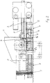
- the illustrated apparatus comprises a conveyor 1, such as a belt conveyor advancing e.g. at a table level A (fig. 2).
- the conveyor is supplied with article goods, comprising flexible thin articles, generally paper goods, into a continuous stack P in such a manner that the individual articles form a stack resting against the conveyor and having the articles in a vertical plane.
- article goods comprising flexible thin articles, generally paper goods
- the feeding apparatus for effecting this is prior known and, in this respect, reference is made e.g. to the Finnish patent 87438 and US-patent 3562775.
- the conveyor 1 terminates upstream of a displacement area which can be an extension of the same table that the advancing conveyor 1 is level with.
- the apparatus includes a displacer device for separating stack portions in the displacement area and for displacing the same aside for subsequent operations.
- the continuous stack advances on top of a table into the displacement area under the action of the conveyor 1 and is held at this point in a sufficiently compressed condition by a counterweight 3, adapted to travel under the control of guides extending parallel to the stack advancing direction and to compress against the first specimen or object of the stack by an appropriately produced force, such as a spring force, a suspended weight pulling the counterweight by way of a rope, or the counterweight's own, sufficiently great mass.
- the displacer device is located along one side of the stack advancing path and includes a separator element 4, comprising a separating wedge penetrating into the stack from the side, as well as a pusher element 5 for pushing a stack portion formed in the displacement area between the separating wedge and the counterweight 3 aside for further processing, for example into the range of action of a gripper, one of the jaws of said gripper being shown in fig. 1 by reference numeral 8.
- the displacer device is also provided with a detector 6 for the edge of a count object, positioned in such a manner that the count object 2 comes into contact therewith as the stack advances whereby the detector 6 produces a signal.
- the detector can be e.g. a conventional micro-switch operating on the contact principle.
- the signal is transmitted to a gripper 7 for clasping its jaws around the edge of the count object 2.
- the gripper 7 is located at the bottom portion of the stack and, immediately after the gripper has completed its action, the above-mentioned separator element 4 penetrates into the stack just before the count object 2 for producing a gap between the gripper-held count object 2 and a stack portion downstream thereof.
- the separator element 4 only penetrates through a part of the stack width, a small distance from the outer stack edge towards the interior. As shown especially in fig.
- one jaw of the gripper comprises a plate 7a placing itself transversely across the advancing path of the count object 2 and the other jaw comprises a nose 7b extending towards the plate from the stack incoming direction and having its end bevelled to align with the surface of said plate 7a.
- the gripper 7 and the separator element 4 can be stationary in the apparatus, the direction of movement of the separating wedge being slightly slanting against the stack advancing direction for producing a sufficient gap. According to a preferred embodiment, those can be made movable by means of an actuator against the stack incoming direction, whereby the separating wedge may move perpendicularly to the stack advancing path.
- the separator element 4 penetrates a small distance into the stack at the end of the sub-frame movement under the pushing action from said actuator 12.
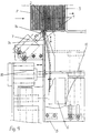
- Figs. 3 and 4 further depict the disposition of components included in the sub-frame B: the plate 7a forming the fixed jaw for the gripper is provided with a recess, wherethrough a strip-like sensor element included in the detector 6 extends from the surface of the plate 7a further in the stack incoming direction and produces the action of the moving component of the gripper 7 when being compressed backwards under the pushing action from the count object 2.
- the separator element 4 is located in front of the plate 7a and its surface facing the stack incoming direction is perpendicular to the stack advancing direction.
- the front face of the pusher element 5 said front face being parallel to the stack edge, pushes the stack portion from between the count object 2 and the counterweight 3 into the operating range of the gripper performing the final packaging.
- the counterweight 3 includes a backing surface which extends in the pushing direction for guiding the stack portion together with an opposing adjustable backing 11.
- the pusher element 5 can be e.g.
- a horizontal frame assembled from metal profiles and mounted on the body of the displacer device so as to effect a reciprocating action by means of an actuator along guides that are perpendicular to the conveyor advancing direction.
- the separator element 4 and the gripper 7 return to the initial position assumed prior to motions or actions effected by the count object 2, and the gripper 7 releases the count object 2, which at the same time, comes into contact with the side face of the pusher element through the action of the conveyor.
- This side face is also provided with a protrusion 9 for setting the free-movement capable counting object 2 flush with the rest of the stack.
- the counterweight 3 When the stack portion has left the separation zone, the counterweight 3 is again able to move against the first specimen or object of the stack arriving on the sorting table, said specimen being the count object 2 that has been set flush with the rest of the stack in the above-mentioned manner.
- the pusher element 5 also retracts.
- the counterweight 3 As shown in figs. 2 and 3, the counterweight 3 is provided with backing surfaces, located above and below the pusher element 5 and fastened to a carriage movable on the body of the displacer device.
- the pusher element 5 and the counterweight 3 can be positioned so as not to interfere with each other's actions.
- the return action of the counterweight 3 can also be accomplished by its own cylinder, which is actuated when the pusher 5 is sufficiently far away.
- the stack P advances on the sorting table until the next count object 2 reaches the detector 4 and the same operations are repeated.
- the actions of various components in the apparatus and the synchronization thereof can be accomplished by means of actuators and control elements known from automatics.
- the actuators producing the actions of various components can be provided e.g. by using pneumatic cylinders.
- the conveyor 1 can be in a continuous motion during the above displacement actions since the material in a stack is capable of compressing when a stack portion is separated, the count object 2 not being able to advance forward.
- the invention can be applied for packaging any paper goods or article goods forming a stack which is characterized by count objects protruding from the stack at set spaces.
Landscapes
- Engineering & Computer Science (AREA)
- Mechanical Engineering (AREA)
- Forming Counted Batches (AREA)
- Control And Other Processes For Unpacking Of Materials (AREA)
- Packaging Of Special Articles (AREA)
- Sheets, Magazines, And Separation Thereof (AREA)
- Special Conveying (AREA)
Claims (5)
- Appareil pour l'emballage de marchandises formant une pile, comportant un transporteur (1) prévu pour transporter une pile continue formée par des objets individuels disposés dans un plan vertical, tels que des enveloppes, dans une direction d'avance parallèle à un niveau de table, ainsi qu'un dispositif de déplacement le long d'un côté de la trajectoire d'avance de pile pourvu d'un détecteur (6) pour un objet de comptage (2) qui dépasse de la pile, d'un élément de séparateur (4) prévu pour pénétrer dans la pile afin de produire un espace entre une partie de pile devant être séparée en premier de la pile et le reste de la pile, ainsi qu'un élément de poussée (5) qui est disposé à l'avant de l'élément de séparateur (4) dans la direction d'avance du transporteur (1) et prévu pour se déplacer sur la trajectoire d'avance de pile afin de déplacer ladite partie de pile vers une autre unité de traitement disposée le long de l'autre côté de la trajectoire d'avance, caractérisé en ce que l'élément de séparateur (4) est aligné avec un dispositif de saisie (7) qui est prévu pour serrer l'objet de comptage (2) qui dépasse.
- Appareil selon la revendication 1, caractérisé en ce que, dans sa position de serrage, ledit dispositif de saisie (7) est prévu pour se déplacer à l'encontre de la direction d'avance du transporteur (1).
- Appareil selon la revendication 2, caractérisé en ce que l'élément de séparateur (4) est rendu mobile avec le dispositif de saisie (7).
- Appareil selon l'une quelconque des revendications précédentes 1 à 3, caractérisé en ce qu'une action de poussée effectuée par l'élément de séparateur (4) est limitée à juste une partie de la largeur de la pile.
- Procédé d'emballage de marchandises formant une pile, dans lequel une pile continue reposant contre un transporteur et avec les articles individuels dans un plan vertical est amené par le transporteur dans une direction parallèle à un niveau de table jusqu'à une zone de déplacement, où des parties de pile sont déplacées de côté pour des opérations consécutives à l'aide d'articles qui dépassent de la pile et formant des objets de comptage, qui sont détectés au moyen d'un détecteur destiné à déplacer une partie de pile en avant de l'objet de comptage, caractérisé en ce qu'un espace entre la partie de pile et le reste de la pile est formé en saisissant l'objet de comptage par un dispositif de saisie (7) et en déplaçant le dispositif de saisie à l'encontre de la direction d'avance du transporteur.
Applications Claiming Priority (3)
| Application Number | Priority Date | Filing Date | Title |
|---|---|---|---|
| FI940416A FI94042C (fi) | 1994-01-28 | 1994-01-28 | Laitteisto pinkassa olevan paperitavaran pakkaamiseksi |
| FI940416 | 1994-01-28 | ||
| PCT/FI1995/000032 WO1995020523A1 (fr) | 1994-01-28 | 1995-01-25 | Appareil de separation d'une partie d'un empilage a l'aide d'un element de separation, et dispositif de prehension d'un repere saillant |
Publications (2)
| Publication Number | Publication Date |
|---|---|
| EP0740628A1 EP0740628A1 (fr) | 1996-11-06 |
| EP0740628B1 true EP0740628B1 (fr) | 1999-06-16 |
Family
ID=8539782
Family Applications (1)
| Application Number | Title | Priority Date | Filing Date |
|---|---|---|---|
| EP95905673A Expired - Lifetime EP0740628B1 (fr) | 1994-01-28 | 1995-01-25 | Appareil de separation d'une partie d'un empilage a l'aide d'un element de separation, et dispositif de prehension d'un repere saillant |
Country Status (8)
| Country | Link |
|---|---|
| US (1) | US6006499A (fr) |
| EP (1) | EP0740628B1 (fr) |
| JP (1) | JPH09508090A (fr) |
| DE (1) | DE69510325T2 (fr) |
| DK (1) | DK0740628T3 (fr) |
| ES (1) | ES2135041T3 (fr) |
| FI (1) | FI94042C (fr) |
| WO (1) | WO1995020523A1 (fr) |
Families Citing this family (5)
| Publication number | Priority date | Publication date | Assignee | Title |
|---|---|---|---|---|
| FI97355C (fi) * | 1995-01-04 | 1996-12-10 | Jopamac Ab Oy | Laitteisto pinkassa olevan paperitavaran pakkaamiseksi |
| JP2008512321A (ja) * | 2004-09-13 | 2008-04-24 | ミードウエストベコ・コーポレーション | 封筒束および封筒束のパッケージの組立方法 |
| US7789226B2 (en) | 2004-09-13 | 2010-09-07 | Meadwestvaco Corporation | Packaged banded envelopes |
| EP3590850B1 (fr) * | 2018-07-02 | 2021-05-05 | H+H GmbH & Co. KG | Procédé et dispositif d'empilement et d'emballage de produits pliés |
| EP3934751B1 (fr) | 2019-03-08 | 2024-07-17 | Mevion Medical Systems, Inc. | Collimateur et dégradeur d'énergie pour système de thérapie par particules |
Family Cites Families (13)
| Publication number | Priority date | Publication date | Assignee | Title |
|---|---|---|---|---|
| US3000151A (en) * | 1956-05-11 | 1961-09-19 | Berkley Machine Co | Method and apparatus for forming and wrapping packs of envelopes and similar articles |
| US3562775A (en) * | 1968-05-09 | 1971-02-09 | Crown Envelope Corp | Envelope boxing method and apparatus |
| US3648431A (en) * | 1969-05-05 | 1972-03-14 | Crown Zellerbach Corp | In-line banding apparatus |
| BE788494A (fr) * | 1971-09-17 | 1973-01-02 | Bobst Fils Sa J | Dispositif selecteur et separateur |
| CH630860A5 (fr) * | 1979-05-18 | 1982-07-15 | Bobst Sa | Dispositif pour recevoir et empaqueter des boites pliantes confectionnees par une plieuse-colleuse. |
| JPS60132849A (ja) * | 1983-12-21 | 1985-07-15 | Kanzaki Paper Mfg Co Ltd | シ−ト束給送方法 |
| US4873813A (en) * | 1984-02-27 | 1989-10-17 | International Paper Box Machine Co., Inc. | Method of packaging box flats |
| US4765451A (en) * | 1984-05-14 | 1988-08-23 | International Paper Box Machine Co., Inc. | Apparatus and method for segregating counted slugs of flats |
| FR2597847B1 (fr) * | 1986-04-29 | 1989-04-21 | Chambon Machines | Machine de reception et d'empilage de flans decoupes |
| DE3641859A1 (de) * | 1986-12-08 | 1988-06-09 | Ficker Otto Ag | Verfahren zum automatischen verpacken von briefhuellen und versandtaschen in ein behaeltnis und verpackungsautomat insbesondere zum durchfuehren der verfahren |
| IT1201604B (it) * | 1986-12-16 | 1989-02-02 | Wramatic Spa | Apparecchiatura e metodo per la selezione automatica di grandi risme sfuse a partire da un pacco di fogli impilati provvisto di segnalini definenti le risme |
| CH680126A5 (fr) * | 1989-10-12 | 1992-06-30 | Schneider Engineering | |
| US5017085A (en) * | 1989-11-14 | 1991-05-21 | Maruishi Iron Works Co., Ltd. | Method and apparatus for separating paper sheets into units and distributing them |
-
1994
- 1994-01-28 FI FI940416A patent/FI94042C/fi active IP Right Grant
-
1995
- 1995-01-25 DE DE69510325T patent/DE69510325T2/de not_active Expired - Fee Related
- 1995-01-25 US US08/682,718 patent/US6006499A/en not_active Expired - Lifetime
- 1995-01-25 JP JP7519901A patent/JPH09508090A/ja active Pending
- 1995-01-25 DK DK95905673T patent/DK0740628T3/da active
- 1995-01-25 ES ES95905673T patent/ES2135041T3/es not_active Expired - Lifetime
- 1995-01-25 EP EP95905673A patent/EP0740628B1/fr not_active Expired - Lifetime
- 1995-01-25 WO PCT/FI1995/000032 patent/WO1995020523A1/fr not_active Ceased
Also Published As
| Publication number | Publication date |
|---|---|
| FI940416A0 (fi) | 1994-01-28 |
| DE69510325T2 (de) | 1999-11-04 |
| ES2135041T3 (es) | 1999-10-16 |
| DE69510325D1 (de) | 1999-07-22 |
| JPH09508090A (ja) | 1997-08-19 |
| EP0740628A1 (fr) | 1996-11-06 |
| WO1995020523A1 (fr) | 1995-08-03 |
| FI94042C (fi) | 1995-07-10 |
| US6006499A (en) | 1999-12-28 |
| FI94042B (fi) | 1995-03-31 |
| DK0740628T3 (da) | 2000-01-17 |
Similar Documents
| Publication | Publication Date | Title |
|---|---|---|
| US4029198A (en) | Method and apparatus for forming groups of bricks | |
| DK640387D0 (da) | Fremgangsmaade og apparat til pakning | |
| FI63690C (fi) | Anordning foer avskiljande av bitar av ett platt material | |
| EP0740628B1 (fr) | Appareil de separation d'une partie d'un empilage a l'aide d'un element de separation, et dispositif de prehension d'un repere saillant | |
| US3690476A (en) | Apparatus for feeding lifts of sheets without marking same | |
| KR860001418Y1 (ko) | 웨브형 소재에 파스너를 부착하는 장치 | |
| FI59545C (fi) | Anordning foer gripande och fasthaollande resp manipulerande av foeremaol | |
| US5711135A (en) | Heat-shrinkable band application machine | |
| EP0528772B1 (fr) | Procédé et dispositif pour alimenter automatiquement un convoyeur avec des flans pris directement d'une boîte | |
| US5423649A (en) | Apparatus for cutting and removing package material | |
| JP3816997B2 (ja) | 印刷機の排紙装置におけるノンストップパイル交換装置 | |
| US3583562A (en) | Methods of and apparatus for stacking veneer sheets | |
| EP0083113B1 (fr) | Méthode et appareil pour ouvrer une paire de bandes de fermeture à glissière | |
| PL321455A1 (en) | Apparatus for taking away rotationally symmetrical containers, each one individually or several ones, fdrom a stream of such containers being moved under impacty pressure and cylinder with controllably movable piston therefor | |
| EP0384255A3 (fr) | Machine pour retirer des lots prédéterminés d'objets plats, tels que des enveloppes ou des feuilles de papier, d'une rangée formée en continue | |
| EP0738682A3 (fr) | Dispositif pour l'alimentation rapide de feuilles supplementaires à un convoyeur de transfert dans une machine d'emballage | |
| JP2001253632A (ja) | 平らな商品片を送る装置 | |
| US4768773A (en) | Apparatus and method for the stacking and storing of workpieces | |
| US3861255A (en) | Device for cutting cavities | |
| JP4478838B2 (ja) | 印刷物抜取装置及びその印刷物抜取方法 | |
| CN209918371U (zh) | 一种冲压零件的在线影像检测设备 | |
| EP0262578A2 (fr) | Séparation et transport d'eléments de vêtement | |
| US4869487A (en) | Method for feeding a blocked sheet unit | |
| US20250257521A1 (en) | A device for capturing a cloth item, and a method of operating the device | |
| JPH07970Y2 (ja) | スライドフアスナ−製造装置におけるグリツパ−装置 |
Legal Events
| Date | Code | Title | Description |
|---|---|---|---|
| PUAI | Public reference made under article 153(3) epc to a published international application that has entered the european phase |
Free format text: ORIGINAL CODE: 0009012 |
|
| 17P | Request for examination filed |
Effective date: 19960826 |
|
| AK | Designated contracting states |
Kind code of ref document: A1 Designated state(s): BE DE DK ES FR GB IT NL SE |
|
| 17Q | First examination report despatched |
Effective date: 19980119 |
|
| GRAG | Despatch of communication of intention to grant |
Free format text: ORIGINAL CODE: EPIDOS AGRA |
|
| GRAG | Despatch of communication of intention to grant |
Free format text: ORIGINAL CODE: EPIDOS AGRA |
|
| GRAH | Despatch of communication of intention to grant a patent |
Free format text: ORIGINAL CODE: EPIDOS IGRA |
|
| RAP1 | Party data changed (applicant data changed or rights of an application transferred) |
Owner name: JOMET OY |
|
| GRAH | Despatch of communication of intention to grant a patent |
Free format text: ORIGINAL CODE: EPIDOS IGRA |
|
| GRAA | (expected) grant |
Free format text: ORIGINAL CODE: 0009210 |
|
| AK | Designated contracting states |
Kind code of ref document: B1 Designated state(s): BE DE DK ES FR GB IT NL SE |
|
| REF | Corresponds to: |
Ref document number: 69510325 Country of ref document: DE Date of ref document: 19990722 |
|
| ITF | It: translation for a ep patent filed | ||
| ET | Fr: translation filed | ||
| REG | Reference to a national code |
Ref country code: ES Ref legal event code: FG2A Ref document number: 2135041 Country of ref document: ES Kind code of ref document: T3 |
|
| REG | Reference to a national code |
Ref country code: DK Ref legal event code: T3 |
|
| PLBE | No opposition filed within time limit |
Free format text: ORIGINAL CODE: 0009261 |
|
| STAA | Information on the status of an ep patent application or granted ep patent |
Free format text: STATUS: NO OPPOSITION FILED WITHIN TIME LIMIT |
|
| 26N | No opposition filed | ||
| PGFP | Annual fee paid to national office [announced via postgrant information from national office to epo] |
Ref country code: SE Payment date: 20001229 Year of fee payment: 7 Ref country code: DK Payment date: 20001229 Year of fee payment: 7 |
|
| REG | Reference to a national code |
Ref country code: GB Ref legal event code: IF02 |
|
| PG25 | Lapsed in a contracting state [announced via postgrant information from national office to epo] |
Ref country code: DK Free format text: LAPSE BECAUSE OF NON-PAYMENT OF DUE FEES Effective date: 20020125 |
|
| PG25 | Lapsed in a contracting state [announced via postgrant information from national office to epo] |
Ref country code: SE Free format text: LAPSE BECAUSE OF NON-PAYMENT OF DUE FEES Effective date: 20020126 |
|
| EUG | Se: european patent has lapsed |
Ref document number: 95905673.0 |
|
| PGFP | Annual fee paid to national office [announced via postgrant information from national office to epo] |
Ref country code: ES Payment date: 20071227 Year of fee payment: 14 |
|
| PGFP | Annual fee paid to national office [announced via postgrant information from national office to epo] |
Ref country code: IT Payment date: 20071227 Year of fee payment: 14 |
|
| PGFP | Annual fee paid to national office [announced via postgrant information from national office to epo] |
Ref country code: GB Payment date: 20071219 Year of fee payment: 14 Ref country code: FR Payment date: 20071217 Year of fee payment: 14 |
|
| PGFP | Annual fee paid to national office [announced via postgrant information from national office to epo] |
Ref country code: DE Payment date: 20080118 Year of fee payment: 14 Ref country code: NL Payment date: 20080116 Year of fee payment: 14 |
|
| PGFP | Annual fee paid to national office [announced via postgrant information from national office to epo] |
Ref country code: BE Payment date: 20080205 Year of fee payment: 14 |
|
| GBPC | Gb: european patent ceased through non-payment of renewal fee |
Effective date: 20090125 |
|
| NLV4 | Nl: lapsed or anulled due to non-payment of the annual fee |
Effective date: 20090801 |
|
| PG25 | Lapsed in a contracting state [announced via postgrant information from national office to epo] |
Ref country code: DE Free format text: LAPSE BECAUSE OF NON-PAYMENT OF DUE FEES Effective date: 20090801 |
|
| REG | Reference to a national code |
Ref country code: FR Ref legal event code: ST Effective date: 20091030 |
|
| PG25 | Lapsed in a contracting state [announced via postgrant information from national office to epo] |
Ref country code: NL Free format text: LAPSE BECAUSE OF NON-PAYMENT OF DUE FEES Effective date: 20090801 Ref country code: GB Free format text: LAPSE BECAUSE OF NON-PAYMENT OF DUE FEES Effective date: 20090125 |
|
| PG25 | Lapsed in a contracting state [announced via postgrant information from national office to epo] |
Ref country code: BE Free format text: LAPSE BECAUSE OF NON-PAYMENT OF DUE FEES Effective date: 20090131 |
|
| REG | Reference to a national code |
Ref country code: ES Ref legal event code: FD2A Effective date: 20090126 |
|
| PG25 | Lapsed in a contracting state [announced via postgrant information from national office to epo] |
Ref country code: FR Free format text: LAPSE BECAUSE OF NON-PAYMENT OF DUE FEES Effective date: 20090202 Ref country code: ES Free format text: LAPSE BECAUSE OF NON-PAYMENT OF DUE FEES Effective date: 20090126 |
|
| PG25 | Lapsed in a contracting state [announced via postgrant information from national office to epo] |
Ref country code: IT Free format text: LAPSE BECAUSE OF NON-PAYMENT OF DUE FEES Effective date: 20090125 |