EP0740633B1 - Kindergesicherte behälterverschlussanordnung - Google Patents
Kindergesicherte behälterverschlussanordnung Download PDFInfo
- Publication number
- EP0740633B1 EP0740633B1 EP95908079A EP95908079A EP0740633B1 EP 0740633 B1 EP0740633 B1 EP 0740633B1 EP 95908079 A EP95908079 A EP 95908079A EP 95908079 A EP95908079 A EP 95908079A EP 0740633 B1 EP0740633 B1 EP 0740633B1
- Authority
- EP
- European Patent Office
- Prior art keywords
- piercing
- container
- closure
- nozzle
- ribs
- Prior art date
- Legal status (The legal status is an assumption and is not a legal conclusion. Google has not performed a legal analysis and makes no representation as to the accuracy of the status listed.)
- Expired - Lifetime
Links
- 230000004323 axial length Effects 0.000 claims description 2
- 230000013011 mating Effects 0.000 claims 1
- 230000000712 assembly Effects 0.000 description 7
- 238000000429 assembly Methods 0.000 description 7
- 238000000034 method Methods 0.000 description 6
- 230000008569 process Effects 0.000 description 6
- 230000004913 activation Effects 0.000 description 2
- 238000010276 construction Methods 0.000 description 2
- 239000003814 drug Substances 0.000 description 2
- 210000004379 membrane Anatomy 0.000 description 2
- 230000035515 penetration Effects 0.000 description 2
- 230000000295 complement effect Effects 0.000 description 1
- 239000002537 cosmetic Substances 0.000 description 1
- 238000007599 discharging Methods 0.000 description 1
- 239000012530 fluid Substances 0.000 description 1
- 239000007788 liquid Substances 0.000 description 1
- 239000012528 membrane Substances 0.000 description 1
- 238000012986 modification Methods 0.000 description 1
- 230000004048 modification Effects 0.000 description 1
- 230000000474 nursing effect Effects 0.000 description 1
- 230000002093 peripheral effect Effects 0.000 description 1
- 238000003825 pressing Methods 0.000 description 1
- 238000007789 sealing Methods 0.000 description 1
Images


Classifications
-
- B—PERFORMING OPERATIONS; TRANSPORTING
- B65—CONVEYING; PACKING; STORING; HANDLING THIN OR FILAMENTARY MATERIAL
- B65D—CONTAINERS FOR STORAGE OR TRANSPORT OF ARTICLES OR MATERIALS, e.g. BAGS, BARRELS, BOTTLES, BOXES, CANS, CARTONS, CRATES, DRUMS, JARS, TANKS, HOPPERS, FORWARDING CONTAINERS; ACCESSORIES, CLOSURES, OR FITTINGS THEREFOR; PACKAGING ELEMENTS; PACKAGES
- B65D51/00—Closures not otherwise provided for
- B65D51/18—Arrangements of closures with protective outer cap-like covers or of two or more co-operating closures
- B65D51/20—Caps, lids, or covers co-operating with an inner closure arranged to be opened by piercing, cutting, or tearing
- B65D51/22—Caps, lids, or covers co-operating with an inner closure arranged to be opened by piercing, cutting, or tearing having means for piercing, cutting, or tearing the inner closure
- B65D51/221—Caps, lids, or covers co-operating with an inner closure arranged to be opened by piercing, cutting, or tearing having means for piercing, cutting, or tearing the inner closure a major part of the inner closure being left inside the container after the opening
- B65D51/222—Caps, lids, or covers co-operating with an inner closure arranged to be opened by piercing, cutting, or tearing having means for piercing, cutting, or tearing the inner closure a major part of the inner closure being left inside the container after the opening the piercing or cutting means being integral with, or fixedly attached to, the outer closure
- B65D51/223—Caps, lids, or covers co-operating with an inner closure arranged to be opened by piercing, cutting, or tearing having means for piercing, cutting, or tearing the inner closure a major part of the inner closure being left inside the container after the opening the piercing or cutting means being integral with, or fixedly attached to, the outer closure the outer closure having to be removed or inverted for piercing or cutting
-
- B—PERFORMING OPERATIONS; TRANSPORTING
- B65—CONVEYING; PACKING; STORING; HANDLING THIN OR FILAMENTARY MATERIAL
- B65D—CONTAINERS FOR STORAGE OR TRANSPORT OF ARTICLES OR MATERIALS, e.g. BAGS, BARRELS, BOTTLES, BOXES, CANS, CARTONS, CRATES, DRUMS, JARS, TANKS, HOPPERS, FORWARDING CONTAINERS; ACCESSORIES, CLOSURES, OR FITTINGS THEREFOR; PACKAGING ELEMENTS; PACKAGES
- B65D2251/00—Details relating to container closures
- B65D2251/0003—Two or more closures
- B65D2251/0006—Upper closure
- B65D2251/0015—Upper closure of the 41-type
-
- B—PERFORMING OPERATIONS; TRANSPORTING
- B65—CONVEYING; PACKING; STORING; HANDLING THIN OR FILAMENTARY MATERIAL
- B65D—CONTAINERS FOR STORAGE OR TRANSPORT OF ARTICLES OR MATERIALS, e.g. BAGS, BARRELS, BOTTLES, BOXES, CANS, CARTONS, CRATES, DRUMS, JARS, TANKS, HOPPERS, FORWARDING CONTAINERS; ACCESSORIES, CLOSURES, OR FITTINGS THEREFOR; PACKAGING ELEMENTS; PACKAGES
- B65D2251/00—Details relating to container closures
- B65D2251/0003—Two or more closures
- B65D2251/0068—Lower closure
- B65D2251/0093—Membrane
- B65D2251/0096—Membrane integral with the container
Definitions
- the present invention relates to child resistant container-closure assemblies and more specifically to improvements facilitating precise activation of the container when it is desired to withdraw the contents.
- Container-closure assemblies of the type to which the present invention relate typically comprise a container made of plastic having a nozzle portion with a puncturable diaphragm, defining a discharge opening and a closure or cap having a piercing element selectively engageable in the diaphragm to form a discharge opening when it is desired to remove the contents of the container.
- Container-closure assemblies of this generally type are not new per se. For example, the patents listed below show container-closure assemblies of this general type:
- the piercing element in the assemblies where the piercing element is on another portion of the closure, unless it is applied in a truly axial direction, the piercing element tends to engage the thick wall portion of the nozzle surrounding the diaphragm which increases the force necessary by the user in the puncturing process.
- Document GB-A-2 100 237 describes a liquid dispensing bottle having a container, a neck portion with a punctureable membran and a cap comprising a spike.
- the spike is mounted on the cap and includes a lower piercing section and an upper nozzle section.
- the cap comprises a pair of elongated, longitudinally-extending and diametrically opposed guide ribs being provided on its interior side for being slidably engaged with a pair of elongated, longitudinally-extending and diametrically opposed guide slots being provided on the neck.
- the present invention is defined by the features of claim 1.
- the present invention provides an improved container-closure assembly which obviates the problems in the prior art noted above.
- the present invention is characterized by novel features of construction and arrangement facilitating application of the closure during the piercing process with a minimum force requirement and thereby obviates the problem of "spurting."
- the particular configuration of the piercing element is such that even if the closure piercing element is presented at a slight angle to the axis of the container, the piercing element is nevertheless directed to the diaphragm when it is moved in a direction to apply it to the nozzle.
- the assembly of the present invention is self aligning and is characterized by minimum contact between the parts and thus produces very minimal, low friction during the piercing process.
- the major force during the piercing process is that of sharpened piercing element engaging the diaphragm.
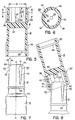
- the container designated by the numeral 10 is a unit dose tube for medicaments having an elongated nozzle 12 at one axial end and a piercable diaphragm 14 in its outer axial end face to define a discharge opening for discharging medicaments when desired.
- the closure generally designated by the numeral 16 comprises a cap portion 18 and a diaphragm piercing portion 20.
- the cap portion 18 and piercing portion 20 are of generally cylindrical shape and are separated by a center wall 22.
- the cap portion 18 is of a predetermined length L to overlie the nozzle 12 when applied thereto in a sealing condition shown in Fig. 3.
- Inner engaging locking means is provided on the nozzle 12 and cap portion 18 for normally seating the cap portion and providing a child resistant feature.
- the locking means comprises a circumferentially extending, radially outwardly directed locking ring 24 spaced upwardly from the juncture of the nozzle 12 and body portion 10 a of the container.
- a circumferentially extending locking groove 26 is provided on the interior wall of the cap portion 18 adjacent its lower terminal edge which snap fits over the locking ring 24 to retain the parts in the position shown in Fig. 3.
- the inner edge of the cap portion 18 is bevelled outwardly as at 28 to facilitate assembly of the cap portion 18 over the locking ring 24 by simply pressing the cap portion 18 downwardly during the assembly process.
- the exterior wall of the cap portion 18 is knurled as at 30 to facilitate assembly and removal of the cap portion by a user.
- the piercing portion 20 of the closure is of cup-like configuration and is of a shorter axial length L p than the diameter D of the pocket and includes a piercing element 34 centrally located in the center wall 22 having a biased or slanted cutting edge 36.
- the exterior of the cap portion 18 is also knurled as at 38 to facilitate handling by a user during manipulation of the cap through various operations.
- the nozzle is provided with a series of circumferentially spaced, longitudinally extending ribs 40.
- the ribs 40 are preferably of a tear drop shape so that lower portion of the ribs 40 bevel downwardly and inwardly at a predetermined angle ⁇ relative to the central axis A-A of the nozzle.
- the enlarged end of each rib 40 as shown in Fig. 7 is also rounded as at 44.
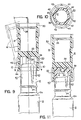
- the ribs thus have a curved outer peripheral shape including a radius R 1 at a point of maximum engagement with the inner walls of the piercing portion 20 of the closure. It is noted that the apex point 41 of the ribs engages the interior wall of the cap portion as best illustrated in Figs. 3 and 4 to reduce friction upon application of the cap to the nozzle 12 and stabilize the cap portion in the fully seated position shown in Fig. 3.
- the ribs 40 engage in the grooves or trackways 42 during application of the piercing portion 20 of the cap to the nozzle 12 in the manner shown in Figs. 8 and 9 and function to align the cap portion 18 axially with the nozzle for accurate penetration of the piercing element 34 to puncture the diaphragm 14.
- the rib 40 and groove 42 arrangement also provides a degree of child resistance since alignment of the groove 42 and ribs 40 is necessary to full seating of the piercing element 34 to penetrate the diaphragm. Further the rib and groove arrangement, particularly the arcuate configuration of the grooves reduces friction during assembly of the closure. In this regard, the radius R 1 of the ribs is smaller than the radius R 2 of the grooves to produce the lower friction and point contact between the parts during a piercing operation.
- the closure is preferably provided with six circumferentially equi-spaced grooves 42 reducing the rotation needed to align the nozzle to an axial piercing position.
- the piercing portion of the closure is designed to prevent engagement of the piercing element 34 with other portions of the nozzle during initial application of the closure 16 regardless of the initial angle of entry. This insures axial alignment of the piercing point 36 with the diaphragm 14 before engagement of the diaphragm the piercing element to puncture the diaphragm 14.
- the tip 48 of the piercing element is spaced inwardly from a plane P-P through the lower terminal edge of the piercing portion, a predetermined distance D equal to at least 1/2 the inner diameter Di of the piercing portion 20 of the closure.
- the interior side wall of the piercing portion 20 snugly embraces the nozzle 12 for proper guidance and yet as shown in Fig. 10 has a small clearance to provide the low friction point contacts during assembly and disassembly of the piercing portion to the nozzle. This relationship provides the desired functional advantages discussed in a piercing portion of minimum height to enhance the cosmetics of the closure assembly.
- the unit dose tubes have an open lower end for filling the product and are pinch sealed after being filled by automatic processing equipment.
- the closure 16 is then applied with the cap portion seated over the nozzle in the manner shown in Fig. 3.
- the locking ring 24 and groove 26 arrangement provides a degree of child resistancy to the assembly.
- the engagement of the ribs with the inner side wall of the cap portion at the apex of the ribs centers the closure on the tube. In other words, the closure is centered on the same axis as the tube axis.
- the user when it is desired to dispense the contents of the tube, the user simply withdraws the closure axially and reverses the closure so that the piercing portion faces downwardly over the nozzle.
- the piercing portion is rotated slightly if necessary to align the ribs in the grooves and by simply urging it axially over the nozzle automatically aligns itself axially to position the piercing element in alignment with the diaphragm.
- This obviates the problem of cockeyed application of the piercing portion to the nozzle which could result in the user attempting to pierce the thick walled portion surrounding the diaphragm. This is particularly important in nursing applications where the systems are activated sometimes in a dimly lit area.
- the rib and groove configuration provides minimum contact areas between the piercing portion and nozzle thereby reducing friction during the piercing process. This also permits a gentle holding force minimizing the "spurting" phenomenon resulting from occasion by squeezing the tube with a large force during the penetration operation.
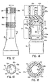
- the assembly includes a container 13 a having a nozzle portion 12 a with a puncturable diaphragm 14 a defining a discharge opening.
- the closure is an elongated tubular member 16 a having a piercing portion 20 a of cup like form and a cap portion 18 a at 21 a .
- the piercing portion has a piercing element 34 a projecting from the center wall 22 a .
- the preferred axial distance D to the tip of the piercing member from the open end of the portion is preferably at least 1/2 the inner diameter D i of the piercing portion 20 a .
- the circumferentially spaced ribs 40 a on the nozzle portion of the closure 12 a are of square cross section.
- the ribs 40 a taper gently and downwardly merge with the nozzle in the manner shown in Fig. 18 and have a slightly rounded upper edge as at 41 a .
- the piercing portion 20 a of the closure is provided with a series of circumferentially spaced, axially extending recesses defining pockets 42 a and are of a complementary square cross section to snugly embrace the ribs 40 a which as indicated above are also of square cross section.
- the exterior circumferential wall of the piercing portion is knurled as at 38 a and in the present instance has a gap 39 in the knurling located adjacent one of the grooves 42 a which defines indicia for aligning the grooves with the ribs when applying the piercing portion to the nozzle of the container.
Landscapes
- Engineering & Computer Science (AREA)
- Mechanical Engineering (AREA)
- Closures For Containers (AREA)
Claims (9)
- Behälter-Verschluss-Anordnung mit einem Behälter (10), der einen Düsenabschnitt (12) mit einem durchstechbaren Diaphragma (14) zum Bilden einer Abgabeöffnung aufweist, und mit einem Verschluss (16) mit einem Durchstechabschnitt (20) von im Wesentlichen tassenförmiger Form, der über der Düse (20) positionierbar ist und ein Durchstechelement (34) aufweist;
gekennzeichnet durch
mehrere sich in axialer Richtung erstreckende in Umfangsrichtung beabstandet angeordnete Rippen (40) an der äußeren Oberfläche des Düsenabschnitts (12) und mehrere in Umfangsrichtung beabstandet angeordnete Nuten (42) an der Innenwand des Durchstechabschnitts (20) um ineinander eingreifende Führungsvorrichtungen zu bilden, wenn der Durchstechabschnitt (20) auf den Düsenabschnitt (12) aufgesetzt wird, um das Diaphragma (14) zu durchstechen, wobei die Anzahl der in Umfangsrichtung beabstandet angeordneten Nuten (42) an der Innenwand des Durchstechabschnitts (20) das zweifache der Anzahl der Rippen (40) an der äußeren Oberfläche des Düsenabschnitts (20), die relativ zueinander beabstandet angeordnet sind, beträgt, so dass die Rippen (40) an der äußeren Oberfläche des Düsenabschnitts (12) in Ausgewählte der Nuten (42) des Durchstechabschnitts eingreifen, wenn der Durchstechabschnitt (20) auf den Düsenabschnitt (12) des Behälters (10) aufgesetzt wird. - Behälter-Verschluss-Anordnung gemäß Anspruch 1, bei der das Durchstechelement (34) in dem Durchstechabschnitt (20) des Verschlusses (16) in axialer Richtung um eine vorgegebene Länge (D), die geringer ist als der Durchmesser (Di) des Durchstechabschnitts (20), zurückgesetzt angeordnet ist.
- Behälter-Verschluss-Anordnung gemäß Anspruch 1 oder 2, bei der die äußere Oberfläche des Durchstechabschnitts (20) zur Bildung einer Griffeinrichtung geriffelt ist.
- Behälter-Verschluss-Anordnung gemäß Anspruch 1 oder 2, bei der der Verschluss (10) einen Deckelabschnitt (18) und einen Diaphragma-Durchstechabschnitt (20) aufweist, die jeweils eine im Wesentlichen tassenförmige Form aufweisen und durch eine Mittenwand (22) getrennt sind, und wobei der Düsenabschnitt und der Deckelabschnitt (12, 18) mit ineinander eingreifenden Verschlussvorrichtungen versehen sind.
- Behälter-Verschluss-Anordnung gemäß Anspruch 4, bei der die ineinander eingreifenden Verschlussvorrichtungen eine radial nach außen gerichtete sich in Umfangsrichtung erstrekkende Rippe (24) an der äußeren Oberfläche des Düsenabschnitts (12) und eine sich in Umfangsrichtung erstreckende dazu passende Nut (26) an der inneren Oberfläche des Dekkelabschnitts (18) aufweisen.
- Behälter-Verschluss-Anordnung gemäß Anspruch 1 oder 2, bei der die Spitze des Durchstechelements (34) nach innen von einer durch die untere Abschlusskante des Durchstechabschnitts gehenden Ebene (P-P) um eine vorgegebene Strecke (D), die wenigstens der Hälfte des Innendurchmessers (Di) des offenen Endes des Durchstechabschnittes (20) des Verschlusses (16) entspricht, zurückgesetzt ist.
- Behälter-Verschluss-Anordnung gemäß Anspruch 1 oder 2, bei der die Rippen (40) und die Nuten (42) im Wesentlichen einen quadratischen Querschnitt aufweisen.
- Behälter-Verschluss-Anordnung nach einem der vorangehenden Ansprüche, bei der der Radius der Rippen (40) kleiner ist als der Radius der Nuten (42).
- Behälter-Verschluss-Anordnung nach einem der vorangehenden Ansprüche, bei dem die Rippen eine tropfenförmige Form aufweisen.
Priority Applications (1)
| Application Number | Priority Date | Filing Date | Title |
|---|---|---|---|
| EP00115253A EP1057740A3 (de) | 1994-01-26 | 1995-01-19 | Kindergesicherte Behälterverschlussanordnung |
Applications Claiming Priority (3)
| Application Number | Priority Date | Filing Date | Title |
|---|---|---|---|
| US188596 | 1994-01-26 | ||
| US08/188,596 US5469980A (en) | 1994-01-26 | 1994-01-26 | Child resistant container closure assembly |
| PCT/US1995/000741 WO1995020532A1 (en) | 1994-01-26 | 1995-01-19 | Child resistant container closure assembly |
Related Child Applications (1)
| Application Number | Title | Priority Date | Filing Date |
|---|---|---|---|
| EP00115253.7 Division-Into | 2000-07-14 |
Publications (3)
| Publication Number | Publication Date |
|---|---|
| EP0740633A1 EP0740633A1 (de) | 1996-11-06 |
| EP0740633A4 EP0740633A4 (de) | 1997-07-16 |
| EP0740633B1 true EP0740633B1 (de) | 2001-12-19 |
Family
ID=22693807
Family Applications (2)
| Application Number | Title | Priority Date | Filing Date |
|---|---|---|---|
| EP00115253A Withdrawn EP1057740A3 (de) | 1994-01-26 | 1995-01-19 | Kindergesicherte Behälterverschlussanordnung |
| EP95908079A Expired - Lifetime EP0740633B1 (de) | 1994-01-26 | 1995-01-19 | Kindergesicherte behälterverschlussanordnung |
Family Applications Before (1)
| Application Number | Title | Priority Date | Filing Date |
|---|---|---|---|
| EP00115253A Withdrawn EP1057740A3 (de) | 1994-01-26 | 1995-01-19 | Kindergesicherte Behälterverschlussanordnung |
Country Status (6)
| Country | Link |
|---|---|
| US (1) | US5469980A (de) |
| EP (2) | EP1057740A3 (de) |
| AU (1) | AU1604595A (de) |
| CA (1) | CA2182115C (de) |
| DE (1) | DE69524734D1 (de) |
| WO (1) | WO1995020532A1 (de) |
Families Citing this family (20)
| Publication number | Priority date | Publication date | Assignee | Title |
|---|---|---|---|---|
| US5553732A (en) * | 1995-01-13 | 1996-09-10 | Nikko Seika Kabushiki Kaisha | Synthetic resin receptacle and method for producing same |
| JP3617732B2 (ja) * | 1996-07-10 | 2005-02-09 | 大和製罐株式会社 | レトルト殺菌可能な容器 |
| US5992668A (en) * | 1996-07-11 | 1999-11-30 | Aptargroup, Inc. | Sealed dispensing closure with a sealed penetrator |
| US6126037A (en) * | 1997-09-09 | 2000-10-03 | Merck & Co., Inc. | Flow control orifice |
| GB2328935A (en) * | 1997-09-09 | 1999-03-10 | Merck & Co Inc | Method for producing a uniform flow control orifice |
| US5927549A (en) * | 1998-03-20 | 1999-07-27 | Aptargroup, Inc. | Dispensing structure with frangible membrane for separating two products |
| US6045004A (en) * | 1998-03-20 | 2000-04-04 | Aptargroup, Inc. | Dispensing structure with dispensing valve and barrier penetrator |
| US5853109A (en) * | 1998-04-29 | 1998-12-29 | Aptargroup, Inc. | Dispensing structure with displaceable penetrator and bistable cover actuator |
| US6003728A (en) * | 1998-10-22 | 1999-12-21 | Aptargroup, Inc. | Dispensing structure with an openable member for separating two products |
| USD425412S (en) * | 1998-11-09 | 2000-05-23 | Fragrance Systems International, Inc. | Domed dual fragrance bottle |
| USD438469S1 (en) | 1998-11-09 | 2001-03-06 | Fragrance Systems International, Inc. | Dual fragrance bottle |
| US6276853B1 (en) | 1999-04-14 | 2001-08-21 | Fragrance Systems International Inc. | Axially aligned, commonly joined dual dispensers |
| US20040234321A1 (en) | 2001-04-25 | 2004-11-25 | Breidenbach Diane C. | Dual cosmetic container |
| US6488427B1 (en) | 2000-02-29 | 2002-12-03 | Diane C. Breidenbach | Cosmetic applicator |
| US7377707B2 (en) | 2000-02-29 | 2008-05-27 | Breidenbach Diane C | Lip product applicator |
| USD558927S1 (en) | 2000-02-29 | 2008-01-01 | Diane Breidenbach | Clear lip applicator |
| USD558926S1 (en) | 2000-02-29 | 2008-01-01 | Diane Breidenbach | Lip applicator |
| US6474508B1 (en) * | 2002-01-24 | 2002-11-05 | Saint-Gobain Calmar Inc. | Unit dose tube and cap assembly |
| US7410071B1 (en) | 2004-04-27 | 2008-08-12 | Rexam Closures And Containers, Inc. | Closure with liner cutter |
| US8070014B2 (en) | 2007-08-24 | 2011-12-06 | Seaquist Closures L.L.C. | Liner piercing twist closure |
Family Cites Families (9)
| Publication number | Priority date | Publication date | Assignee | Title |
|---|---|---|---|---|
| US4234103A (en) * | 1978-03-31 | 1980-11-18 | Baxter Travenol Laboratories, Inc. | Diagnostic reagent dispensing bottle |
| US4340147A (en) * | 1980-11-03 | 1982-07-20 | Mack-Wayne Plastics Company | Cap with built in piercing device |
| US4614437A (en) * | 1984-11-02 | 1986-09-30 | Dougherty Brothers Company | Mixing container and adapter |
| US4765518A (en) | 1986-06-05 | 1988-08-23 | C P Packaging, Inc. | Unit dose container with captive cap |
| US4867326A (en) | 1988-08-25 | 1989-09-19 | Cp Packaging | Child resistant cap and tube assembly |
| US4884703A (en) | 1988-09-27 | 1989-12-05 | Cp Packaging Inc. | Container and closure assembly |
| US5042690A (en) | 1990-02-08 | 1991-08-27 | Cp Packaging, Inc. | Unit dose assembly |
| US5052589A (en) * | 1990-02-08 | 1991-10-01 | Cp Packaging, Inc. | Unit dose assembly |
| US5090582A (en) * | 1990-10-16 | 1992-02-25 | Baxter International Inc. | Bottle cap |
-
1994
- 1994-01-26 US US08/188,596 patent/US5469980A/en not_active Expired - Lifetime
-
1995
- 1995-01-19 WO PCT/US1995/000741 patent/WO1995020532A1/en not_active Ceased
- 1995-01-19 CA CA002182115A patent/CA2182115C/en not_active Expired - Fee Related
- 1995-01-19 AU AU16045/95A patent/AU1604595A/en not_active Abandoned
- 1995-01-19 EP EP00115253A patent/EP1057740A3/de not_active Withdrawn
- 1995-01-19 DE DE69524734T patent/DE69524734D1/de not_active Expired - Lifetime
- 1995-01-19 EP EP95908079A patent/EP0740633B1/de not_active Expired - Lifetime
Also Published As
| Publication number | Publication date |
|---|---|
| CA2182115C (en) | 2007-03-20 |
| US5469980A (en) | 1995-11-28 |
| EP0740633A1 (de) | 1996-11-06 |
| EP1057740A3 (de) | 2001-03-28 |
| CA2182115A1 (en) | 1995-08-03 |
| EP1057740A2 (de) | 2000-12-06 |
| EP0740633A4 (de) | 1997-07-16 |
| WO1995020532A1 (en) | 1995-08-03 |
| DE69524734D1 (de) | 2002-01-31 |
| AU1604595A (en) | 1995-08-15 |
Similar Documents
| Publication | Publication Date | Title |
|---|---|---|
| EP0740633B1 (de) | Kindergesicherte behälterverschlussanordnung | |
| EP1011602B1 (de) | Penetrator für eine Behälterkappe und Verfahren zu dessen Herstellung | |
| US4614437A (en) | Mixing container and adapter | |
| EP1129016B1 (de) | Verschlussvorrichtung für einen mit einer membran abgedichteten behälter | |
| EP1345647B1 (de) | Behälter mit einlage zur aufbewahrung und abgabe von medikamenten | |
| US5954233A (en) | Sealed container | |
| CN113853345B (zh) | 用于浓缩再填充囊的囊和塞子 | |
| EP0090015B1 (de) | Behälter mit integraldeckel | |
| JP2001333961A (ja) | 液体成分を混合する装置 | |
| US4976379A (en) | Dispensing container with integral funnel | |
| WO2001017869A1 (en) | Packaging for multi-component materials and methods of making the same | |
| CN113811395B (zh) | 用于浓缩再填充囊的囊和盖组件 | |
| US7017782B2 (en) | Child resistant safety cap for applicator tubes | |
| CN113874120A (zh) | 用于浓缩再填充囊的囊和塞子 | |
| US5590798A (en) | Container-closure assembly | |
| AU700814B2 (en) | Container-closure assembly | |
| US5000349A (en) | Aseptic package tap | |
| EP0342464A1 (de) | Aseptische Behälterausgiessvorrichtung | |
| AU3434002A (en) | Container cap assembly having an enclosed penetrator | |
| HK1136512A1 (en) | Fluid delivery assembly |
Legal Events
| Date | Code | Title | Description |
|---|---|---|---|
| PUAI | Public reference made under article 153(3) epc to a published international application that has entered the european phase |
Free format text: ORIGINAL CODE: 0009012 |
|
| 17P | Request for examination filed |
Effective date: 19960801 |
|
| AK | Designated contracting states |
Kind code of ref document: A1 Designated state(s): DE DK ES FR GB IT NL SE |
|
| A4 | Supplementary search report drawn up and despatched |
Effective date: 19970526 |
|
| AK | Designated contracting states |
Kind code of ref document: A4 Designated state(s): DE DK ES FR GB IT NL SE |
|
| 17Q | First examination report despatched |
Effective date: 19990323 |
|
| GRAG | Despatch of communication of intention to grant |
Free format text: ORIGINAL CODE: EPIDOS AGRA |
|
| GRAG | Despatch of communication of intention to grant |
Free format text: ORIGINAL CODE: EPIDOS AGRA |
|
| GRAH | Despatch of communication of intention to grant a patent |
Free format text: ORIGINAL CODE: EPIDOS IGRA |
|
| GRAH | Despatch of communication of intention to grant a patent |
Free format text: ORIGINAL CODE: EPIDOS IGRA |
|
| GRAA | (expected) grant |
Free format text: ORIGINAL CODE: 0009210 |
|
| AK | Designated contracting states |
Kind code of ref document: B1 Designated state(s): DE DK ES FR GB IT NL SE |
|
| PG25 | Lapsed in a contracting state [announced via postgrant information from national office to epo] |
Ref country code: NL Free format text: LAPSE BECAUSE OF FAILURE TO SUBMIT A TRANSLATION OF THE DESCRIPTION OR TO PAY THE FEE WITHIN THE PRESCRIBED TIME-LIMIT Effective date: 20011219 Ref country code: IT Free format text: LAPSE BECAUSE OF FAILURE TO SUBMIT A TRANSLATION OF THE DESCRIPTION OR TO PAY THE FEE WITHIN THE PRESCRIBED TIME-LIMIT;WARNING: LAPSES OF ITALIAN PATENTS WITH EFFECTIVE DATE BEFORE 2007 MAY HAVE OCCURRED AT ANY TIME BEFORE 2007. THE CORRECT EFFECTIVE DATE MAY BE DIFFERENT FROM THE ONE RECORDED. Effective date: 20011219 Ref country code: FR Free format text: LAPSE BECAUSE OF FAILURE TO SUBMIT A TRANSLATION OF THE DESCRIPTION OR TO PAY THE FEE WITHIN THE PRESCRIBED TIME-LIMIT Effective date: 20011219 |
|
| REG | Reference to a national code |
Ref country code: GB Ref legal event code: IF02 |
|
| REF | Corresponds to: |
Ref document number: 69524734 Country of ref document: DE Date of ref document: 20020131 |
|
| PG25 | Lapsed in a contracting state [announced via postgrant information from national office to epo] |
Ref country code: SE Free format text: LAPSE BECAUSE OF FAILURE TO SUBMIT A TRANSLATION OF THE DESCRIPTION OR TO PAY THE FEE WITHIN THE PRESCRIBED TIME-LIMIT Effective date: 20020319 Ref country code: GB Free format text: LAPSE BECAUSE OF NON-PAYMENT OF DUE FEES Effective date: 20020319 Ref country code: DK Free format text: LAPSE BECAUSE OF FAILURE TO SUBMIT A TRANSLATION OF THE DESCRIPTION OR TO PAY THE FEE WITHIN THE PRESCRIBED TIME-LIMIT Effective date: 20020319 |
|
| PG25 | Lapsed in a contracting state [announced via postgrant information from national office to epo] |
Ref country code: DE Free format text: LAPSE BECAUSE OF FAILURE TO SUBMIT A TRANSLATION OF THE DESCRIPTION OR TO PAY THE FEE WITHIN THE PRESCRIBED TIME-LIMIT Effective date: 20020320 |
|
| NLV1 | Nl: lapsed or annulled due to failure to fulfill the requirements of art. 29p and 29m of the patents act | ||
| PG25 | Lapsed in a contracting state [announced via postgrant information from national office to epo] |
Ref country code: ES Free format text: LAPSE BECAUSE OF FAILURE TO SUBMIT A TRANSLATION OF THE DESCRIPTION OR TO PAY THE FEE WITHIN THE PRESCRIBED TIME-LIMIT Effective date: 20020627 |
|
| EN | Fr: translation not filed | ||
| PLBE | No opposition filed within time limit |
Free format text: ORIGINAL CODE: 0009261 |
|
| STAA | Information on the status of an ep patent application or granted ep patent |
Free format text: STATUS: NO OPPOSITION FILED WITHIN TIME LIMIT |
|
| GBPC | Gb: european patent ceased through non-payment of renewal fee |
Effective date: 20020319 |
|
| 26N | No opposition filed | ||
| NLV1 | Nl: lapsed or annulled due to failure to fulfill the requirements of art. 29p and 29m of the patents act |