EP0740639B1 - Procede et dispositif pour detecter l'enroulement d'un fil sur un cylindre en rotation - Google Patents
Procede et dispositif pour detecter l'enroulement d'un fil sur un cylindre en rotation Download PDFInfo
- Publication number
- EP0740639B1 EP0740639B1 EP95940113A EP95940113A EP0740639B1 EP 0740639 B1 EP0740639 B1 EP 0740639B1 EP 95940113 A EP95940113 A EP 95940113A EP 95940113 A EP95940113 A EP 95940113A EP 0740639 B1 EP0740639 B1 EP 0740639B1
- Authority
- EP
- European Patent Office
- Prior art keywords
- light
- roller
- monitoring region
- yarn
- light source
- Prior art date
- Legal status (The legal status is an assumption and is not a legal conclusion. Google has not performed a legal analysis and makes no representation as to the accuracy of the status listed.)
- Expired - Lifetime
Links
- 238000000034 method Methods 0.000 title claims abstract description 22
- 238000004804 winding Methods 0.000 title abstract description 42
- 230000008569 process Effects 0.000 title abstract description 4
- 238000012544 monitoring process Methods 0.000 claims abstract description 36
- 238000009987 spinning Methods 0.000 claims description 3
- 230000001678 irradiating effect Effects 0.000 claims description 2
- 238000012545 processing Methods 0.000 claims description 2
- 230000015572 biosynthetic process Effects 0.000 claims 2
- 238000011156 evaluation Methods 0.000 abstract description 13
- 230000004044 response Effects 0.000 description 9
- 238000001514 detection method Methods 0.000 description 7
- 230000008901 benefit Effects 0.000 description 5
- 230000007257 malfunction Effects 0.000 description 4
- 239000000700 radioactive tracer Substances 0.000 description 4
- 230000001960 triggered effect Effects 0.000 description 4
- 238000003384 imaging method Methods 0.000 description 3
- 230000008859 change Effects 0.000 description 2
- 238000005520 cutting process Methods 0.000 description 2
- 238000011161 development Methods 0.000 description 2
- 230000018109 developmental process Effects 0.000 description 2
- 238000004519 manufacturing process Methods 0.000 description 2
- 230000004888 barrier function Effects 0.000 description 1
- 230000005540 biological transmission Effects 0.000 description 1
- 238000011109 contamination Methods 0.000 description 1
- 238000012937 correction Methods 0.000 description 1
- 230000002349 favourable effect Effects 0.000 description 1
- 238000012423 maintenance Methods 0.000 description 1
- 238000005259 measurement Methods 0.000 description 1
- 238000012806 monitoring device Methods 0.000 description 1
- 230000003287 optical effect Effects 0.000 description 1
- 230000005855 radiation Effects 0.000 description 1
- 238000003860 storage Methods 0.000 description 1
- 238000011144 upstream manufacturing Methods 0.000 description 1
Images
Classifications
-
- B—PERFORMING OPERATIONS; TRANSPORTING
- B65—CONVEYING; PACKING; STORING; HANDLING THIN OR FILAMENTARY MATERIAL
- B65H—HANDLING THIN OR FILAMENTARY MATERIAL, e.g. SHEETS, WEBS, CABLES
- B65H63/00—Warning or safety devices, e.g. automatic fault detectors, stop-motions ; Quality control of the package
- B65H63/003—Warning or safety devices, e.g. automatic fault detectors, stop-motions ; Quality control of the package responsive to winding of yarns around rotating cylinders
-
- B—PERFORMING OPERATIONS; TRANSPORTING
- B65—CONVEYING; PACKING; STORING; HANDLING THIN OR FILAMENTARY MATERIAL
- B65H—HANDLING THIN OR FILAMENTARY MATERIAL, e.g. SHEETS, WEBS, CABLES
- B65H2701/00—Handled material; Storage means
- B65H2701/30—Handled filamentary material
- B65H2701/31—Textiles threads or artificial strands of filaments
Definitions
- the invention relates to a method for recognizing a Thread winding on a rotating roller according to the generic term of claim 1 and a device for Execution of this procedure.
- the coil diameter of a winding body in particular a spool of a synthetic thread to determine a pivotally arranged sensing roller.
- the feeler roller lies on the winding body and rotates with it this. If there is a thread malfunction in the area of the feeler roller, so the thread can be wound on the feeler roller will.
- Such an unwanted thread winding leads to a malfunction.
- the malfunction can also in a traversing device upstream of the winding head lead to a disturbance and in a short time by itself rapidly increasing volume of thread winding on the Tracer roller considerable damage to the thread winding device cause.
- the present invention is therefore based on the object a method for early detection of an unwanted Winding up anywhere in the monitored area a rotating roller in a thread processing or to specify thread winding device which is safe and works reliably.
- a device is also to be specified by means of which the detection of a winding thread on a roller of such a device with high functional reliability and a short response time.
- the method according to the invention opens a new path to Detection of thread winding on a rotating, partial walked on by the thread wound roller. It is proposed to do this by a light source Beams of light at an angle of incidence a to a surface line to project the roller onto the roller in such a way that this over the entire length of the surveillance area
- the roller extends as a strip of light and this from the thread winding reflected scattered light by means of a sensor device to detect and trigger an alarm signal, if at least a thread wrap in the monitoring area of the roller has been determined.
- the position of the light sensor results themselves from the claims.
- the evaluation device with respect to the monitoring area of the Radial vibrations of the roller have no influence on the detection of the thread. This may result in already found a single thread wrap on the roller will.
- an arrangement of the light sensor is also possible in other areas.
- the measure, the roller with a grinding incidental, parallel or yourself Irradiating widening light beam offers in particular the advantage that the entire surveillance area between two normal planes at a distance from each other Roller is set with a single light source and associated imaging optics is illuminated when the angle of attack a is correctly set to the roll surface. This depends on the amplitude of the vibrations of the Roll in winding operation, the manufacturing tolerances at Manufacture of the roller and the height of any existing Thrust rings on the roller.
- This angle of attack ⁇ lies in Range between 3 ° and 10 °, preferably at 5 ° and in individual cases on the basis of the structural conditions Attempt found.
- a winder is detected therefore simultaneously throughout the surveillance area in the state of the art only a selective detection by successive measurements was possible.
- the finding of the thread then takes place in that the thread, which from a plurality of filaments, light reflects and as it were on the roller of the thread winding device flashes. This flashing is from the evaluation device recognized as scattered light and then triggered a signal.
- Irradiation of the sensing roller over the entire surveillance area with a grinding light beam therefore make sure that the thread flashes, even if there are one or a few turns, there the roller itself emits little light towards the light sensor reflects and therefore the incident stray light as a deviation from any existing basic radiation is recognized.
- the light is preferably monochrome.
- the roller can e.g. B. be irradiated by means of a laser light source. This is not necessary, but it has the advantage of possibly required lens systems of imaging optics easier to be able to interpret, because the monochrome light a uniform Has wavelength and corrections to the lenses only for this uniform wavelength must be taken into account. Also can be disturbed by external influences of the day or Ambient light can be switched off more easily with filters.
- a laser light source is preferably an inexpensive one Possibility of a sharply defined light beam monochrome To provide light. Electronic laser light sources that working in near-infrared wavelength ranges are for preferred the present invention.
- the roller is the thread delivery or thread take-off roller (godet) of a filament spinning machine can be.
- it is preferably the contact or Tracer roller of a thread winding device in such a Spinning machine for synthetic filament threads, the basic one Structure, for example, from US-A-5,029,762 is known.
- an optoelectric device (light sensor) has, which in a preferred embodiment in essentially in the middle of the surveillance area and with Distance is arranged on the side of the roller that is not is wrapped in the thread, as well as an evaluation device, which triggers a signal.
- the optoelectric device is preferably electrical with the evaluation device connected.
- Thread winding on the rotating roller reflected light is detected and fed into an evaluation device preferably standing electrical signal converted, the evaluation device when exceeded a tolerance limit triggers another signal at which it is an alarm signal or a thread cutting signal can act.
- the device comprises an outside of the surveillance area arranged light source, the one Beams of light in the longitudinal direction of the roller and under one small angle of attack to the roller aimed at this.
- the Light source preferably emits monochrome light, for example the light of a laser light source.
- it can a rectangular in cross section or a Monitoring area adapted, expanded with suitable optics Be a bundle of light.
- the optoelectric device preferably comprises one Imaging optics with one arranged behind a converging lens Light sensor.
- the light sensor can be a CCD array or a photodiode.
- a sensor in the form of a CCD array the advantage that this is read out according to the clock signal can be.
- a sensing roller Thread take-up device can measure the measured values of the light sensor (Interference reflections) from this area easily with digital logic be hidden.
- the electronics enable one quick response to errors in the millisecond range can lie.
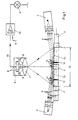
- the feeler roller 1 is at a distance from the feeler roller by means of two and arranged opposite to each other, in one Radial plane lying light sources 3, 4 irradiated. Of the Angle of attack a, under which the beam of light or rays 5 occurs on the feeler roller 1, is chosen so pointed that each area of the optoelectric device (light sensor) 6 - 8 facing side of the surveillance area the roller 1 is illuminated.
- the light sources 3, 4 emit a light beam 5 with a rectangular cross section a width of about 10 mm and a depth of a few mm, preferably 1 mm. This is done with, for example achieved collimator optics, not shown, the includes cylindrical lenses.
- the light beam 5 is in each case in the monitoring area of roller 1 as a line or as in The circumferential direction of the roller is very narrow, along a surface line running light band 50 projected onto the roller. To cover the entire monitoring area 20 between two in the Spaced normal planes of the roller 1 is formed, To illuminate, the light sources 3, 4 are on the side outside of the monitoring area 20.
- an optoelectric device (Light sensor) 6 - 8 essentially in the center the monitoring area 20 of the roller 1.
- the facility comprises a converging lens 7, behind which a light sensor 8 is arranged.
- the light sensor 8 is made of photodiodes built up the striking light into a photo stream 15 convert.
- a mask 9 is arranged in front of the light sensor 8, which hides the area of the thrust rings 2.
- the light sensor 8 is equipped with an evaluation device 10 and these are electrically connected to an alarm display device 11.
- the present invention eliminates the undesirable Winding a thread on a feeler roller 1 over the early detection of the entire length of the monitoring area 20, especially after one or a few loops, so that a thread cut can be triggered before consequential damage arise on the winding machine.
- the response times of both possible sensors are clear less than 2 milliseconds. This response time is sufficient at winding speeds of 8000 m / min and at one Tracer roller diameter of 85 mm for consequential damage to the to avoid endangered components of the winding device.
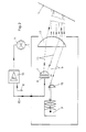
- FIG. 1 shows a modified device for winder monitoring according to Fig. 1.
- Fig. 1 There is the image from the Perspective of the incident light beam 5, which from the Light source 3 via an optical system which comprises the lenses 16, 17 on the feeler roller 1, not shown here is projected.
- the reflected light 13 is through deflected the convex surface of the lens 17 and on the opto-electrical evaluation device (light sensor) 7 - 8 depicted in the beam path of the reflected light rays 13 is arranged, this detected and in a photo stream 15 converts.
- the difference signal is in the Evaluation device 10 then amplified and can be exceeded an alarm device of a predefinable threshold value 11 or the like.
- the advantage of the arrangement according to FIG. 2 is that no components of the monitoring device in the immediate vicinity Must be attached close to the feeler roller 1 to be monitored, so that the designer has greater freedom in terms of housing, assembly and maintenance of the light source 3 (Transmitter) and the light sensor 7, 8 (receiving part) and the has an intermediate look.
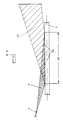
- FIG. 3 finally shows a schematic arrangement in FIG a radial plane of the roller 1, which in the present case has no thrust rings, for example the location of the Light source 3 with respect to the roller 1, namely outside of Monitoring area 20 of this roller. It also shows that Assignment of the light sensor 6-8 to detect the at an im Monitoring area 20 possible thread winding 12 generated Flare. This stray light is created by reflection, Diffraction and refraction of the incident light beam 5 to the fine filament threads (capillary threads) of the thread winding, the are predominantly opaque.
- the light sensor 6-8 is arranged on the side of the roller 1 be above the roller 1, d. H. above the tangential plane the roller 1, in which the light band 50 lies.
- the light sensor 6-8 can be arranged anywhere be. It only has to be guaranteed that the light sensor 6-8 that arises on a thread or a thread winding Scattered light and not that reflected by the roller 1 itself Beam of light measures and as a deviation of a photo stream clear differences in light intensity can be determined.
Landscapes
- Engineering & Computer Science (AREA)
- Textile Engineering (AREA)
- Quality & Reliability (AREA)
- Filamentary Materials, Packages, And Safety Devices Therefor (AREA)
- Investigating Materials By The Use Of Optical Means Adapted For Particular Applications (AREA)
Abstract
Claims (20)
- Procédé d'identification d'un enroulement de fil (12) (= bobineuse) sur un rouleau rotatif (1) qui est partiellement entouré par un fil, selon lequel le faisceau lumineux d'une source lumineuse (3, 4) est dirigé sur une zone de surveillance du rouleau (1) par le fait que la source lumineuse (3, 4) est disposée en dehors de la zone de surveillance et est dirigée obliquement sur la zone de surveillance,caractérisé en ce queet selon lequel la lumière réfléchie à partir de la zone de surveillance est détectée par un détecteur photoélectrique (6 à 8), et selon lequel la source lumineuse (3, 4) et le détecteur photoélectrique (6 à 8) sont situés du côté du rouleau (1) qui n'est pas entouré par le fil,le faisceau lumineux (5) est dirigé sur le rouleau (1) de telle sorte qu'il se reflète en tant que bande lumineuse (50) sur une génératrice du rouleau (1) et recouvre la zone de surveillance,et en ce que le détecteur photoélectrique (6 à 8) est disposé en dehors du faisceau lumineux (5) dirigé par la source lumineuse (3, 4) sur la zone de surveillance (20), et en dehors de celui réfléchi par le rouleau (1).
- Procédé selon la revendication 1,
caractérisé en ce quela bande lumineuse (50) a une largeur inférieure à 5 mm, de préférence inférieure à 2 mm. - Procédé selon les revendications 1 et 2,
caractérisé en ce quele faisceau lumineux (5) est dirigé sur le rouleau (1) suivant un angle d'incidence α compris entre 3 et 8°, de préférence de l'ordre de 5°. - Procédé selon l'une quelconque des revendications 1 à 3,
caractérisé en ce quela lumière projetée sur l'arbre (1) est monochromatique. - Procédé selon la revendication 4,
caractérisé en ce queles rayons lumineux (5) sont la lumière d'une source de lumière laser. - Procédé selon l'une quelconque des revendications 1 à 5
caractérisé en ce queun faisceau lumineux (5) est à chaque fois projeté sur le rouleau (1) par deux sources lumineuses (3, 4) situées l'une en face de l'autre, de telle sorte qu'une bande lumineuse (50) sensiblement commune soit reflétée sur le rouleau (1) dans la zone de surveillance (20), et en ce que le détecteur photoélectrique (6 à 8) est disposé en dehors du faisceau lumineux (5) dirigé par les sources lumineuses (3, 4) sur la zone de surveillance (20) du rouleau (1) et réfléchi par le rouleau (1). - Procédé selon l'une quelconque des revendications 1 à 6,
caractérisé en ce quele rouleau (1) est le rouleau palpeur d'un dispositif d'enroulement de fil pour fils synthétiques sans fin. - Procédé selon l'une quelconque des revendications 1 à 7,
caractérisé en ce que,pour détecter la lumière réfléchie par un enroulement de fil (12), le détecteur photoélectrique (6 à 8) est pour l'essentiel disposé en étant centré au-dessus de la zone de surveillance du rouleau (1). - Procédé selon la revendication 1,
caractérisé en ce que,pour détecter la lumière réfléchie par un enroulement de fil (12), le détecteur photoélectrique (6 à 8) est disposé dans le rayonnement parallèlement à la source lumineuse (3) émettant les rayons lumineux (5). - Procédé selon la revendication 9,
caractérisé en ce quela lumière reçue par le détecteur photoélectrique (6 à 8) est détectée en tant que signal électrique (15), dont la variation est amplifiée pour le déclenchement d'un signal d'alarme. - Dispositif d'identification d'un enroulement de fil (12) (bobineuse) sur un rouleau rotatif (1) d'un dispositif de traitement et d'enroulement de fil destiné à la mise en oeuvre du procédé selon l'une quelconque des revendications 1 à 10, comportant une source lumineuse (3, 4) destinée à projeter de la lumière sur le rouleau (1) dans une zone de surveillance, et un détecteur photoélectrique (6 à 8) destiné à détecter la lumière réfléchie à partir de la zone de surveillance,
caractérisé en ce quela source lumineuse (3, 4) est dirigée sur la zone de surveillance (20) du rouleau (1) suivant un angle d'incidence α tel qu'une bande lumineuse (50) soit reflétée dans la zone de surveillance sur une génératrice du rouleau (1), laquelle recouvre la longueur de la zone de surveillance, et en ce que le détecteur photoélectrique (6 à 8) est disposé en dehors du faisceau lumineux (5) dirigé par la source lumineuse (3, 4) sur la zone de surveillance (20) du rouleau (1), et en dehors de celui réfléchi par le rouleau (1). - Dispositif selon la revendication 11,
caractérisé en ce quel'angle d'incidence (α) de la source lumineuse (3) par rapport à l'axe de rotation du rouleau (1) se situe entre 3 et 10°, de préférence à 5°. - Dispositif selon la revendication 11 ou 12,
caractérisé en ce quela source lumineuse (3) projette de la lumière monochromatique sur l'arbre (1), qui est de préférence émise par une source de lumière laser. - Dispositif selon l'une quelconque des revendications 11 à 13,
caractérisé en ce quedeux sources lumineuses (3, 4) sont dirigées sur la zone de surveillance (20) du rouleau (1) suivant un angle d'incidence α tel qu'une bande lumineuse (50) sensiblement commune soit reflétée dans la zone de surveillance (20) du rouleau (1),laquelle recouvre la longueur de la zone de surveillance (20), et en ce que le détecteur photoélectrique (6 à 8) est disposé en dehors du faisceau lumineux (5) dirigé par les deux sources lumineuses (3, 4) sur le rouleau (1) dans la zone de surveillance (20), et en dehors de celui réfléchi par le rouleau (1). - Dispositif selon l'une quelconque des revendications 11 à 14,
caractérisé en ce quele détecteur photoélectrique (6 à 8) comporte une lentille convexe (7), qui est disposée dans le rayonnement du faisceau lumineux (5) réfléchi par l'enroulement de fil (12). - Dispositif selon l'une quelconque des revendications 11 à 15,
caractérisé en ce quele détecteur photoélectrique (8) comporte un réseau CCD. - Dispositif selon l'une quelconque des revendications 11 à 15,
caractérisé en ce quele détecteur photoélectrique (8) comporte une photodiode. - Dispositif selon l'une au moins des revendications 11 à 17, dans le cas duquel le rouleau (1) comporte plusieurs bagues de butée (2) formées à écartement axial,
caractérisé en ce queun masque (9) est disposé dans le rayonnement entre la lentille convexe (7) et le détecteur photoélectrique (8). - Dispositif selon l'une quelconque des revendications 11 à 18,
caractérisé en ce quele rouleau (1) est le rouleau palpeur (1) d'un dispositif d'enroulement de fil ou d'une galette de déplacement de fil d'un métier à filer pour fils synthétiques. - Dispositif selon la revendication 11,
caractérisé en ce quele détecteur photoélectrique (6 à 8) est disposé dans un plan qui est parallèle au plan dans lequel est situé la source lumineuse (3) qui dirige le faisceau lumineux (5) sur le rouleau (1).
Applications Claiming Priority (3)
| Application Number | Priority Date | Filing Date | Title |
|---|---|---|---|
| DE4441736 | 1994-11-23 | ||
| DE4441736 | 1994-11-23 | ||
| PCT/DE1995/001625 WO1996015969A1 (fr) | 1994-11-23 | 1995-11-22 | Procede et dispositif pour detecter l'enroulement d'un fil sur un cylindre en rotation |
Publications (2)
| Publication Number | Publication Date |
|---|---|
| EP0740639A1 EP0740639A1 (fr) | 1996-11-06 |
| EP0740639B1 true EP0740639B1 (fr) | 1998-08-26 |
Family
ID=6533979
Family Applications (1)
| Application Number | Title | Priority Date | Filing Date |
|---|---|---|---|
| EP95940113A Expired - Lifetime EP0740639B1 (fr) | 1994-11-23 | 1995-11-22 | Procede et dispositif pour detecter l'enroulement d'un fil sur un cylindre en rotation |
Country Status (5)
| Country | Link |
|---|---|
| US (1) | US5767963A (fr) |
| EP (1) | EP0740639B1 (fr) |
| CN (1) | CN1069602C (fr) |
| DE (2) | DE19543118A1 (fr) |
| WO (1) | WO1996015969A1 (fr) |
Families Citing this family (14)
| Publication number | Priority date | Publication date | Assignee | Title |
|---|---|---|---|---|
| US5964391A (en) * | 1997-10-24 | 1999-10-12 | E. I. Du Pont De Nemours And Company | Wrap detection device |
| DE19941722A1 (de) * | 1999-09-02 | 2001-03-08 | Schlafhorst & Co W | Vorrichtung zum Überwachen einer unerwünschten Fadenwickelbildung auf einer Walze einer Textilmaschine |
| DE10057170A1 (de) * | 2000-11-16 | 2002-05-23 | Rieter Ag Maschf | Ermittlung von Störstellen |
| ITMI20042528A1 (it) * | 2004-01-10 | 2005-03-28 | Saurer Gmbh & Co Kg | Metodo e dispositivo per rilevare l'avvolgimento di una fibra nonche'macchina per il taglio di fibre |
| DE102007062631B4 (de) | 2007-12-22 | 2018-07-26 | Saurer Germany Gmbh & Co. Kg | Vorrichtung zur Überwachung einer unerwünschten Fadenwickelbildung in einer Textilmaschine |
| US7590314B1 (en) * | 2008-09-04 | 2009-09-15 | Spirit Aerosystems, Inc. | Fiber optic sensor for tow wrap |
| US9333548B2 (en) * | 2013-08-12 | 2016-05-10 | Victaulic Company | Method and device for forming grooves in pipe elements |
| DE102014011937A1 (de) * | 2014-08-12 | 2016-02-18 | Saurer Germany Gmbh & Co. Kg | Vorrichtung zum Detektieren einer unerwünschten Fadenwickelbildung |
| FR3033322B1 (fr) * | 2015-03-06 | 2019-09-13 | Saurer Germany Gmbh & Co. Kg | Procede et dispositif de detection de la fin de devidage d'un element filiforme |
| JP7119970B2 (ja) * | 2018-12-12 | 2022-08-17 | トヨタ自動車株式会社 | 位置検出方法及び位置検出装置 |
| CN115697873A (zh) * | 2020-05-12 | 2023-02-03 | 塞玛2有限公司 | 用于自动地检验织物用线轴的质量的装置和方法 |
| WO2022067756A1 (fr) * | 2020-09-30 | 2022-04-07 | 深圳烯湾科技有限公司 | Procédé de commande pour l'enroulement et le durcissement de fibres, et dispositif d'enroulement de fibres durcissant à la lumière |
| CN112408099B (zh) * | 2020-11-26 | 2022-09-13 | 重庆市齐垚机电设备有限公司 | 一种管子收卷监测系统、管子收卷装置及管子收卷方法 |
| DE102023116979A1 (de) | 2023-06-28 | 2025-01-02 | Maschinenfabrik Rieter Ag | Verfahren zur Überwachung wenigstens einer Walze eines Streckwerks einer Textilmaschine, Textilmaschine sowie Verwendung einer Überwachungseinheit |
Family Cites Families (12)
| Publication number | Priority date | Publication date | Assignee | Title |
|---|---|---|---|---|
| DE885908C (de) * | 1950-12-08 | 1953-08-10 | Bobingen Ag Fuer Textil Faser | Wickelschutz fuer Walzenanordnungen |
| US3712743A (en) * | 1971-01-05 | 1973-01-23 | Eastman Kodak Co | Apparatus for detecting and measuring yarn defects and irregularities |
| US4108708A (en) * | 1975-01-09 | 1978-08-22 | Milliken Research Corporation | Scrim machine |
| GB1557167A (en) * | 1975-06-30 | 1979-12-05 | Ici Ltd | Method and apparatus for detecting yarn on rods and severing the yarn |
| US4188545A (en) * | 1975-06-30 | 1980-02-12 | Imperial Chemical Industries Limited | Yarn processing, method and apparatus |
| NL7508287A (nl) * | 1975-07-11 | 1977-01-13 | Philips Nv | Werkwijze en inrichting voor het in vorm trek- ken van een schaduwmasker en schaduwmasker ge- trokken volgens deze werkwijze of met deze in- richting. |
| DE3133494C2 (de) * | 1981-08-25 | 1984-11-22 | Erwin Sick Gmbh Optik-Elektronik, 7808 Waldkirch | Opto-elektronische Überwachungsvorrichtung |
| JPS6262937A (ja) * | 1985-09-10 | 1987-03-19 | Murata Mach Ltd | 巻糸パツケ−ジの巻形検査装置 |
| DE3805068A1 (de) * | 1988-02-18 | 1989-08-31 | Gebhard Birkle | Verfahren und vorrichtung zum optischen abtasten einer objektebene zwecks erkennung sich aendernder ueberhoehungen auf dieser ebene |
| DE8916288U1 (de) * | 1988-12-22 | 1997-05-22 | Barmag Ag, 42897 Remscheid | Aufspulmaschine |
| DE4131664A1 (de) * | 1991-09-23 | 1993-03-25 | Rieter Ingolstadt Spinnerei | Verfahren und vorrichtung zum erfassen von garnfehlern |
| SE511091C2 (sv) * | 1993-04-21 | 1999-08-02 | Sipra Patent Beteiligung | Garnmatare för textilmaskiner |
-
1995
- 1995-11-18 DE DE19543118A patent/DE19543118A1/de not_active Withdrawn
- 1995-11-22 EP EP95940113A patent/EP0740639B1/fr not_active Expired - Lifetime
- 1995-11-22 DE DE59503337T patent/DE59503337D1/de not_active Expired - Fee Related
- 1995-11-22 US US08/682,583 patent/US5767963A/en not_active Expired - Fee Related
- 1995-11-22 WO PCT/DE1995/001625 patent/WO1996015969A1/fr not_active Ceased
- 1995-11-22 CN CN95191320A patent/CN1069602C/zh not_active Expired - Fee Related
Also Published As
| Publication number | Publication date |
|---|---|
| CN1069602C (zh) | 2001-08-15 |
| DE59503337D1 (de) | 1998-10-01 |
| CN1139412A (zh) | 1997-01-01 |
| DE19543118A1 (de) | 1996-05-30 |
| EP0740639A1 (fr) | 1996-11-06 |
| US5767963A (en) | 1998-06-16 |
| WO1996015969A1 (fr) | 1996-05-30 |
Similar Documents
| Publication | Publication Date | Title |
|---|---|---|
| EP0650915B1 (fr) | Dispositif pour contrôler la qualité de l'enroulement de bobines de fil et utilisation du dispositif dans un bobinoir ou un métier à filer | |
| EP0572592B1 (fr) | Detection de fibres etrangeres dans des fils | |
| EP3208370B1 (fr) | Dispositif et procédé de détermination du diamètre d'un ballon formé par un fil en mouvement dans un poste de travail d'une machine textile formant des ballons de fil | |
| EP0740639A1 (fr) | Procede et dispositif pour detecter l'enroulement d'un fil sur un cylindre en rotation | |
| EP0693451B1 (fr) | Procédé pour mesurer optiquement l'état de la surface de bobines de fil | |
| EP1655599A2 (fr) | Détecteur de fil | |
| EP2044430A2 (fr) | Procédé et agencement pour déterminer la qualité du fil et/ou la qualité de bobine d'un fil continu à l'aide d'anémometrie laser doppler | |
| EP0837829B1 (fr) | Detecteur optoelectronique et dispositif de mesure et d'amenee de fil de trame | |
| DE19510808C1 (de) | Verfahren und Vorrichtung zum Erkennen einer Restmenge des Greiferfadens bei einer Nähmaschine | |
| DE2653298A1 (de) | Pruefvorrichtung zum pruefen der enden von zigaretten | |
| DE3938934A1 (de) | Vorrichtung zur fadenueberwachung | |
| DE69113797T2 (de) | Fadenliefervorrichtung. | |
| DE10342383A1 (de) | Verfahren und Vorrichtung zum berührungslosen Bestimmen der Geschwindigkeit eines laufenden Fadens | |
| DE3834478C2 (fr) | ||
| DE102018131264A1 (de) | Spulmaschine sowie Vorrichtung zur Erkennung von Fadenresten | |
| DE102015209957A1 (de) | Garnüberwachungsvorrichtung | |
| WO1991010898A1 (fr) | Dispositif pour le controle photoelectrique d'un fil defilant | |
| DE19944958C2 (de) | Leit- oder Kontaktwalzenanordnung zum Handhaben einer Materialbahn, insbesondere in einer Rollenwickelvorrichtung | |
| EP1225149B1 (fr) | Dispositif pour détecter le diamètre réel de la bobine dans un bobinoir pour mèche de filaments et bobinoir avec un tel dispositif | |
| DE4236413C1 (de) | Vorrichtung zum Überwachen wenigstens eines fadenförmigen Objekts | |
| DE4124750A1 (de) | Vorrichtung zum erfassen eines bewicklungsfehlers | |
| DE19941723A1 (de) | Vorrichtung zum Überwachen einer unerwünschten Fadenwickelbildung auf einer Walze einer Textilmaschine | |
| DE4300581C2 (de) | Vorrichtung zur fotoelektrischen Überwachung | |
| DE69404742T2 (de) | Vorrichtung zur optischen Detektion eines Schussfadens und diese Vorrichtung umfassender Schussfadenspeicher | |
| DE3811563C2 (fr) |
Legal Events
| Date | Code | Title | Description |
|---|---|---|---|
| PUAI | Public reference made under article 153(3) epc to a published international application that has entered the european phase |
Free format text: ORIGINAL CODE: 0009012 |
|
| 17P | Request for examination filed |
Effective date: 19960809 |
|
| AK | Designated contracting states |
Kind code of ref document: A1 Designated state(s): BE CH DE FR IT LI NL |
|
| GRAG | Despatch of communication of intention to grant |
Free format text: ORIGINAL CODE: EPIDOS AGRA |
|
| 17Q | First examination report despatched |
Effective date: 19971119 |
|
| GRAG | Despatch of communication of intention to grant |
Free format text: ORIGINAL CODE: EPIDOS AGRA |
|
| GRAH | Despatch of communication of intention to grant a patent |
Free format text: ORIGINAL CODE: EPIDOS IGRA |
|
| GRAH | Despatch of communication of intention to grant a patent |
Free format text: ORIGINAL CODE: EPIDOS IGRA |
|
| GRAA | (expected) grant |
Free format text: ORIGINAL CODE: 0009210 |
|
| AK | Designated contracting states |
Kind code of ref document: B1 Designated state(s): BE CH DE FR IT LI NL |
|
| REG | Reference to a national code |
Ref country code: CH Ref legal event code: EP |
|
| REG | Reference to a national code |
Ref country code: CH Ref legal event code: NV Representative=s name: BARMAG GMBH ENGINEERING & MANUFACTURING |
|
| REF | Corresponds to: |
Ref document number: 59503337 Country of ref document: DE Date of ref document: 19981001 |
|
| ET | Fr: translation filed | ||
| PLBE | No opposition filed within time limit |
Free format text: ORIGINAL CODE: 0009261 |
|
| STAA | Information on the status of an ep patent application or granted ep patent |
Free format text: STATUS: NO OPPOSITION FILED WITHIN TIME LIMIT |
|
| 26N | No opposition filed | ||
| PGFP | Annual fee paid to national office [announced via postgrant information from national office to epo] |
Ref country code: NL Payment date: 19991122 Year of fee payment: 5 |
|
| PG25 | Lapsed in a contracting state [announced via postgrant information from national office to epo] |
Ref country code: NL Free format text: LAPSE BECAUSE OF NON-PAYMENT OF DUE FEES Effective date: 20010601 |
|
| NLV4 | Nl: lapsed or anulled due to non-payment of the annual fee |
Effective date: 20010601 |
|
| PGFP | Annual fee paid to national office [announced via postgrant information from national office to epo] |
Ref country code: FR Payment date: 20021118 Year of fee payment: 8 |
|
| PGFP | Annual fee paid to national office [announced via postgrant information from national office to epo] |
Ref country code: CH Payment date: 20021122 Year of fee payment: 8 Ref country code: BE Payment date: 20021122 Year of fee payment: 8 |
|
| PGFP | Annual fee paid to national office [announced via postgrant information from national office to epo] |
Ref country code: DE Payment date: 20021220 Year of fee payment: 8 |
|
| PG25 | Lapsed in a contracting state [announced via postgrant information from national office to epo] |
Ref country code: LI Free format text: LAPSE BECAUSE OF NON-PAYMENT OF DUE FEES Effective date: 20031130 Ref country code: CH Free format text: LAPSE BECAUSE OF NON-PAYMENT OF DUE FEES Effective date: 20031130 Ref country code: BE Free format text: LAPSE BECAUSE OF NON-PAYMENT OF DUE FEES Effective date: 20031130 |
|
| BERE | Be: lapsed |
Owner name: *BARMAG A.G. Effective date: 20031130 |
|
| PG25 | Lapsed in a contracting state [announced via postgrant information from national office to epo] |
Ref country code: DE Free format text: LAPSE BECAUSE OF NON-PAYMENT OF DUE FEES Effective date: 20040602 |
|
| REG | Reference to a national code |
Ref country code: CH Ref legal event code: PL |
|
| PG25 | Lapsed in a contracting state [announced via postgrant information from national office to epo] |
Ref country code: FR Free format text: LAPSE BECAUSE OF NON-PAYMENT OF DUE FEES Effective date: 20040730 |
|
| REG | Reference to a national code |
Ref country code: FR Ref legal event code: ST |
|
| PG25 | Lapsed in a contracting state [announced via postgrant information from national office to epo] |
Ref country code: IT Free format text: LAPSE BECAUSE OF NON-PAYMENT OF DUE FEES Effective date: 20051122 |