EP0740824B1 - Dispositif d'affichage selectif d'informations - Google Patents
Dispositif d'affichage selectif d'informations Download PDFInfo
- Publication number
- EP0740824B1 EP0740824B1 EP94904682A EP94904682A EP0740824B1 EP 0740824 B1 EP0740824 B1 EP 0740824B1 EP 94904682 A EP94904682 A EP 94904682A EP 94904682 A EP94904682 A EP 94904682A EP 0740824 B1 EP0740824 B1 EP 0740824B1
- Authority
- EP
- European Patent Office
- Prior art keywords
- poster
- unwinder
- magazine
- posters
- display window
- Prior art date
- Legal status (The legal status is an assumption and is not a legal conclusion. Google has not performed a legal analysis and makes no representation as to the accuracy of the status listed.)
- Expired - Lifetime
Links
- 230000009471 action Effects 0.000 claims abstract description 5
- 238000005096 rolling process Methods 0.000 claims abstract 4
- 230000033001 locomotion Effects 0.000 claims description 6
- 238000000605 extraction Methods 0.000 description 9
- 238000004804 winding Methods 0.000 description 7
- 230000008901 benefit Effects 0.000 description 6
- 230000014759 maintenance of location Effects 0.000 description 4
- 238000000034 method Methods 0.000 description 4
- 230000000694 effects Effects 0.000 description 2
- 230000004048 modification Effects 0.000 description 2
- 238000012986 modification Methods 0.000 description 2
- 230000008569 process Effects 0.000 description 2
- 241000287107 Passer Species 0.000 description 1
- 230000009118 appropriate response Effects 0.000 description 1
- 230000001174 ascending effect Effects 0.000 description 1
- 230000000712 assembly Effects 0.000 description 1
- 238000000429 assembly Methods 0.000 description 1
- 238000013461 design Methods 0.000 description 1
- 238000011161 development Methods 0.000 description 1
- 230000018109 developmental process Effects 0.000 description 1
- 238000009434 installation Methods 0.000 description 1
- 230000003993 interaction Effects 0.000 description 1
- 238000012423 maintenance Methods 0.000 description 1
- 238000004519 manufacturing process Methods 0.000 description 1
- 210000000056 organ Anatomy 0.000 description 1
- 230000001681 protective effect Effects 0.000 description 1
- 238000011144 upstream manufacturing Methods 0.000 description 1
- 238000012800 visualization Methods 0.000 description 1
Images


Classifications
-
- G—PHYSICS
- G09—EDUCATION; CRYPTOGRAPHY; DISPLAY; ADVERTISING; SEALS
- G09F—DISPLAYING; ADVERTISING; SIGNS; LABELS OR NAME-PLATES; SEALS
- G09F11/00—Indicating arrangements for variable information in which the complete information is permanently attached to a movable support which brings it to the display position
- G09F11/30—Indicating arrangements for variable information in which the complete information is permanently attached to a movable support which brings it to the display position the display elements being fed one by one from storage place to a display position
- G09F11/32—Indicating arrangements for variable information in which the complete information is permanently attached to a movable support which brings it to the display position the display elements being fed one by one from storage place to a display position the feeding means comprising belts or chains, e.g. endless belts or chains
- G09F11/325—Indicating arrangements for variable information in which the complete information is permanently attached to a movable support which brings it to the display position the display elements being fed one by one from storage place to a display position the feeding means comprising belts or chains, e.g. endless belts or chains the display elements being stored in the form of rolls fixed in between transporting belts or chains
Definitions
- the present invention relates to a device for the selective display of information for advertising purposes.
- Each of the posters is provided at one of its ends with an elastic return means (such as a spring) making it possible to wind the poster inside its roller in the absence of any action. external, and at the other of its ends, an external extraction means making it possible to annihilate the opposite force of the return means and unroll said poster out of its roll.
- an elastic return means such as a spring
- This device has the drawback of not allowing direct access to a poster without having to scroll in a direction where in the other all the posters which precede it on the transporter, this once the poster presented behind the window has been disconnected from the retention means so that it can be stored in its cartridge.
- a display device with two storage magazines and meeting the definitions of the preamble of claim 1 is described by US-A-2 195 249.
- the technical problem to be solved by the object of the present invention is therefore to propose a display device which is simple to implement, inexpensive, making it possible to define and modify simply the order and the duration of presentation of each poster. and to minimize the downtime between display and display operations.
- the fundamental concept of the invention consists in using a display device of the type recalled above and consisting of a self-supporting frame comprising two roll storage magazines arranged at its ends, behind the display window and on the height of the latter, so that the above unwinder can ensure the unfolding of the poster of a store behind the window at the same time as the winding of the poster of the other store just presented, and vice versa.
- the aforementioned unwinder evolves from one end of the self-supporting frame where a store is installed (said first store) to its opposite end where the other store is installed (said second store).
- This unwinder is provided with a device for hooking the means for extracting the posters from their roll, so that, when the unwinder is moved from the first magazine to the second magazine, it ensures, behind the window d display, the winding of the poster of the second store at the same time as the unfolding of the poster of the first store, and, when the unwinder is set in reverse movement, it ensures the winding of a poster of the first store at the same time as the unfolding of a poster from the second store.
- the process is dynamic since it is it which comes next to the means of extracting a selected poster from one or the other of the stores and which ensures the process and presentation of a poster behind the window.
- the unwinder also guides the winding of the poster on itself inside its roller, and this at the same time as the unfolding of the following poster.
- the device of the invention has a notable advantage in that the storage stores for the rolls containing the posters and the unwinder are dynamic. A judiciously programmed interaction between them by electronic servo drive motors will minimize downtime.
- Figure 1 is a partially exploded view of such a device.
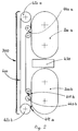
- Figure 2 is a vertical sectional view of the same device.
- Figure 3 is a detail view of an element of this device.
- Figure 4 is an enlarged view of an embodiment detail of this device.
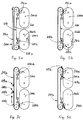
- Figures 5a, 5b, 5c, 5d are schematic views of this device, illustrating a display cycle.
- the self-supporting frame 100 which will be described a little more in detail at the end of the description consists in particular of a rigid framework which has the purpose of serving as a logical structure for the various dynamic organs of the device (which will be detailed below). in their realization) adapted to be interchangeable and respect the modular architecture.
- the stores 200a and 200b located in the context of the invention at the top and bottom of the frame 100 are intended to ensure the dynamic storage of rollers 210a, 210b containing posters wound on themselves 211a, 211b information carrier for advertising purposes.
- the poster 211a illustrated by way of example in the drawing of FIG. 3 is provided at one of its ends with an elastic return means not illustrated, making it possible in particular to ensure automatic winding of displays it inside its roller 210a in the absence of any external action.
- This elastic return may be constituted by a coil type spring wedged between the roller housing and an axis mounted in free rotation on which is fixed one end of said poster.
- the other end of the poster 21a1, situated outside the housing of the roller 210a, is preformed with a hem, in which a rod 212a is threaded serving as extraction means allowing, using a appropriate attachment means, to annihilate the opposite force of the spring return means and to unroll the poster 21 out of its roll 210a.
- a rod 212a is threaded serving as extraction means allowing, using a appropriate attachment means, to annihilate the opposite force of the spring return means and to unroll the poster 21 out of its roll 210a.
- the poster 21a takes place outside of the roller 210a while remaining taut by the opposite tension exerted by the return force E of the spring.
- the spring return force ensures the winding of the poster 21a inside the roller 210a as shown by the arrow E.
- the stores 200a and 200b each consist of an endless chain 220a, 220b, each driven around two cylinders of which at least one is a motor.
- These endless chains 220a and 220b are intended to receive (preferably removably) the rollers 210a and 210b containing the posters 211a and 211b.
- the purpose of the rotary drive of the endless chains around their return cylinders is to be able to present a roller 210 in front of the unwinder, whatever its position in its magazine.
- the embodiment of stores 200a and 200b is given as a preferred embodiment because the return of the endless chains around their cylinders makes it possible to have all the useful height released behind the display window 300, while reducing the thickness of the frame imposed by the diameter of said cylinders.
- the number of posters is lower, it will be possible to replace the magazines 200a and 200b by two drums or barrels receiving peripherally the rollers 210a to 210b.
- the magazines 200a and 200b thus defining independent modular assemblies, can also be quickly interchanged in the display device of the invention.
- the braced flanges 110 and 120 constituting the self-supporting frame 100 of the device are provided with notches 111 and 121 opening towards the rear of the frame and allowing the rapid installation or removal of a magazine 200a or 200b.
- the display window 300 making it possible to view the information of the poster 211a or 211b unrolled behind it, is also fixed interchangeably on the flanges 110, 120 of the frame 100, over almost the entire height of the latter, delimiting the useful operating height. Under particular conditions of application, in particular to avoid problems of reflection of incident light, the display window 300 may be devoid of any protective glazing.
- the display device comprises an integrated light box 500 which is inserted into the thickness of the unwinder 400 in the space cleared between the return cylinders 420a, 420b.
- This light box 500 placed at a distance from the window 300 to clear a passage to the posters 211a, 211b which presents themselves, makes it possible to illuminate the latter at the rear and possibly to reinforce their maintenance.
- the unwinder 400 is, in turn, disposed between the display window 300 and the two stores 200a and 200b. It consists of an endless belt 410 driven around two return cylinders 420a and 420b, wedged between the two flanges 110 and 120 of the frame 100 in the upper and lower part of the latter.
- a motor 430 drives the endless belt 410 around said cylinders 420a, 420b.
- the endless belt 410 is provided with two hooks 411a, 411b arranged opposite and acting as attachment means for the extraction means of posters 211a or 211b.
- hooks 41a, 411b are, on the one hand, sufficiently spaced from one another, and, on the other hand, sufficiently open to allow the attachment or detachment of the rod forming the aforesaid extraction means 212a and 212b of posters 21a1, 211b.
- the number of pairs of hooks 411a, 411b distributed over the width of the endless strip 410 will depend on the width of the posters 211a or 211b. For this purpose, it will be possible to position pairs of hooks at the two ends of the rod 21 the 212b possibly protruding from the posters 21 la or 2116 and / or in eyelets formed along the length of the hem formed at the ends of the posters 211a , 211b to receive said rods.
- the endless belt 410 of the unwinder 400 is equipped at its two ends, upstream of the return cylinders 420a, 420b with two belt guide means 440a, 440b, each formed of two rollers arranged in S, the two guide means being intended to define at the top and bottom points of the unwinder, a rectilinear portion of the strip 410 beyond the curved portion of the endless chains of the above stores 200a and 200b.
- the guide devices 440a, 440b have the particular advantage of giving an angle of inclination to the hooks 411a, 411b improving the attachment and / or detachment of the rods 212a, 212b.
- Another advantage of the guide means 440a, 440b is to be able to scroll the posters over the entire height of the window 300 and to park the hooks 411a, 411b outside the path of the rollers 210a, 210b, and avoid any interference with them. this.
- these guide means are also used as end of travel detectors for the running of the endless belt 410.
- FIG. 5a illustrates the display device according to which a poster 221a of the storage magazine 200a is presented behind the display window 300 and held in this position by the hook 411b of the unwinder 400 in the low position of the device at the level from store 200b.
- FIG. 5b The purpose of FIG. 5b is to illustrate the setting in motion of the magazine 200b so that the roller 210b is positioned in front of the hooking means 41a, 411b of the unwinder 400.
- the object of FIG. 5c is to illustrate the setting in upward movement of the unwinder 400 which has enabled the hook 411b to secure the attachment of the rod 212b corresponding to the poster 211b wound in the selected roller 210b, so that the poster 211b can take place behind the display window 300 at the same time as the poster 21a of the roller 210a of the magazine 200a is automatically wound in its roller under the effect of its return spring and guided by the movement ascending from the unwinder 400.
- FIG. 5d illustrates the poster 211b entirely unrolled behind the window 300 and the unhooking of the rod 212a from the hook 41 la, so that the roller 210a is disengaged from the unwinder 400.
- a new display cycle can then begin to positioning of a new poster for store 200a.
- the device according to the present invention has several advantages over existing devices:
Landscapes
- Physics & Mathematics (AREA)
- General Physics & Mathematics (AREA)
- Engineering & Computer Science (AREA)
- Theoretical Computer Science (AREA)
- Displays For Variable Information Using Movable Means (AREA)
- Selective Calling Equipment (AREA)
- Financial Or Insurance-Related Operations Such As Payment And Settlement (AREA)
Description
- La présente invention concerne un dispositif d'affichage sélectif d'informations à vocation publicitaire.
- Les évolutions des exigences des exploitants de dispositifs d'affichage ont fait progresser la technique en la matière, et on connaît aujourd'hui divers procédés permettant d'afficher successivement plusieurs informations différentes.
- Le marché publicitaire actuel, notamment en ce qui concerne les manifestations fortement médiatisées, ne trouve pas dans l'utilisation de tels dispositifs de réponse appropriée à ses besoins. En effet, il est devenu indispensable d'optimiser le rendement d'une campagne d'affichage en disposant de moyens dont la mise en oeuvre est simple, rapide, peu coûteuse, tout en offrant une grande souplesse dans le choix et la modification de l'ordre des passages et des durées d'affichage.
- L'invention s'applique plus particulièrement aux dispositifs d'affichage du type de celui comportant :
- un magasin de stockage de rouleaux renfermant des affiches support d'informations portées par des bandes souples enroulées sur elles-mêmes,
- une fenêtre d'affichage permettant de visualiser des informations d'une affiche déroulée devant elle,
- et un dérouleur permettant de dérouler sélectivement les affiches hors de leur rouleau et derrière la fenêtre d'affichage.
- Chacune des affiches est pourvue à une de ses extrémités, d'un moyen de rappel élastique (tel qu'un ressort) permettant d'assurer l'enroulement de l'affiche à l'intérieur de son rouleau en l'absence de toute action extérieure, et à l'autre de ses extrémités, d'un moyen d'extraction extérieur permettant d'annihiler la force opposée du moyen de rappel et de dérouler ladite affiche hors de son rouleau.
- Le brevet français n° 2 647246 propose une solution pour réaliser un tel dispositif d'affichage. A cet effet, ce dispositif comprend :
- un transporteur (magasin) en boucle fermée entraîné par un moteur et guidé de manière à passer devant une fenêtre d'affichage,
- une pluralité de supports répartis le long du transporteur et solidaires de celui-ci, chacun de ces supports étant destiné à recevoir une cartouche (rouleau) orientée perpendiculairement à l'axe de défilement du transporteur,
- des moyens permettant d'assurer une fixation déconnectable desdites cartouches sur lesdits supports,
- des moyens de rétention (dérouleur) disposés à demeure en un emplacement situé en regard du trajet des moyens d'extraction des affiches, lorsque les cartouches sont entraînées par le transporteur et au voisinage de la fenêtre d'affichage,
- des moyens de commande du moteur et de sélection des affiches aptes à agir sur les moyens de rétention, en vue de provoquer la rétention des moyens d'extraction d'une affiche sélectionnée lors de son passage en regard dudit emplacement, de manière à provoquer le déroulement de l'affiche dans l'aire de présentation sous l'effet de l'entraînement de la cartouche par le transporteur, et à stopper le transporteur lorsque l'affiche est totalement déroulée.
- Ce dispositif présente l'inconvénient de ne pas permettre l'accès direct à une affiche sans avoir à faire défiler dans un sens où dans l'autre toutes les affiches qui la précèdent sur le transporteur, ceci une fois que l'affiche présentée derrière la fenêtre ait été déconnectée des moyens de rétention afin qu'elle puisse être rangée dans sa cartouche.
- Un dispositif d'affichage à deux magasins de stockage et répondant aux définitions du préambule de la revendication 1 est décrit par US-A-2 195 249.
- Le problème technique à résoudre par l'objet de la présente invention, est donc de proposer un dispositif d'affichage simple de mise en oeuvre, peu coûteux, permettant de définir et de modifier simplement l'ordre et la durée de présentation de chaque affiche et de réduire au maximum les temps morts entre les opérations de désaffichage et d'affichage.
- Pour répondre à ce problème, le concept fondamental de l'invention consiste à utiliser un dispositif d'affichage du type de celui rappelé ci-dessus et se composant d'un bâti autoporteur comportant deux magasins de stockage de rouleaux disposés à ses extrêmes, derrière la fenêtre d'affichage et sur la hauteur de cette dernière, de telle sorte que le susdit dérouleur puisse assurer le déroulement de l'affiche d'un magasin derrière la fenêtre en même temps que l'enroulement de l'affiche de l'autre magasin venant d'être présentée, et vice-versa.
- Un tel dispositif d'affichage offre de nombreux avantages car il permet de réduire au minimum les temps morts entre les opérations de désaffichage et d'affichage, puisque :
- pendant le temps de visualisation d'une affiche d'un magasin derrière la fenêtre d'affichage, une autre affiche est sélectionnée dans l'autre magasin,
- le déroulement d'une affiche d'un magasin s'opère en même temps que l'enroulement d'une affiche venant d'être présentée par l'autre magasin,
- En outre, il autorise un ordre non établi de défilement des affiches.
- Selon une caractéristique particulièrement avantageuse de l'invention, le susdit dérouleur évolue d'une extrémité du bâti autoporteur où est installé un magasin (dit premier magasin) vers son extrémité opposée où est installé l'autre magasin (dit deuxième magasin). Ce dérouleur est pourvu d'un dispositif d'accrochage du moyen d'extraction des affiches hors de leur rouleau, de telle sorte que, lorsque le dérouleur est mis en mouvement du premier magasin vers le deuxième magasin, il assure, derrière la fenêtre d'affichage, l'enroulement de l'affiche du deuxième magasin en même temps que le déroulement de l'affiche du premier magasin, et, lorsque le dérouleur est mis en mouvement inverse, il assure l'enroulement d'une affiche du premier magasin en même temps que le déroulement d'une affiche du deuxième magasin.
- Par rapport aux dispositifs antérieurs, le déroulement est dynamique puisque c'est lui qui vient en regard des moyens d'extraction d'une affiche sélectionnée de l'un où l'autre des magasins et qui assure le déroulement et la présentation d'une affiche derrière la fenêtre.
- Selon la disposition principale de l'invention, le dérouleur guide également l'enroulement de l'affiche sur elle-même à l'intérieur de son rouleau, et ce en même temps que le déroulement de l'affiche suivante.
- Le dispositif de l'invention présente un avantage notable dans la mesure où les magasins de stockage des rouleaux contenant les affiches et le dérouleur sont dynamiques. Une interaction judicieusement programmée entre eux par une électronique d'asservissement des moteurs d'entraînement permettra de réduire au minimum les temps morts.
- Selon une forme de réalisation préférentielle de l'invention permettant d'optimiser au maximum la surface d'affichage du dispositif de l'invention, il est possible de concevoir un dispositif comportant deux fenêtres d'affichage et deux dérouleurs disposés de part et d'autre des deux magasins. Cette application sera notamment utile lorsque le dispositif d'affichage sera installé de manière à ce que les deux fenêtres opposées soient exposées à la vue du public.
- L'invention venant d'être évoquée ci-dessus dans sa forme la plus élémentaire, d'autres caractéristiques et d'autres avantages ressortiront plus clairement à la lecture de la description qui suit donnant, à titre d'exemple non limitatif, un mode de réalisation d'un dispositif d'affichage illustrant les concepts fondamentaux de l'invention.
- Cette description est annexée de dessins sur lesquels:
- La figure 1 est une vue partiellement éclatée d'un tel dispositif.
- La figure 2 est une vue en coupe verticale du même dispositif.
- La figure 3 est une vue de détail d'un élément de ce dispositif.
- La figure 4 est une vue agrandie d'un détail de réalisation de ce dispositif.
- Les figures 5a, 5b, 5c, 5d sont des vues schématiques de ce dispositif, illustrant un cycle d'affichage.
- Tel que représenté sur les dessins des figures 1 et 2, le dispositif d'affichage de l'invention se compose d'un bâti autoporteur 100 sur lequel sont agencés :
- deux magasins 200a et 200b de stockage de rouleaux 210 et 220,
- une fenêtre d'affichage 300,
- et un dérouleur 400.
- Le bâti autoporteur 100 qui sera décrit un peu plus dans le détail à la fin de la description est notamment constitué d'une ossature rigide qui a pour objet de servir de structure logique aux différents organes dynamiques du dispositif (qui vont être détaillés ci-après dans leur réalisation) adaptés pour être interchangeables et respecter l'architecture modulaire.
- Les magasins 200a et 200b situés dans le contexte de l'invention en haut et en bas du bâti 100 ont pour objet d'assurer le stockage dynamique de rouleaux 210a, 210b renfermant des affiches enroulées sur elles-mêmes 211a, 211b support d'informations à vocation publicitaire.
- Comme montré sur la figure 3, l'affiche 211a illustrée à titre d'exemple sur le dessin de la figure 3 est pourvue à une de ses extrémités d'un moyen de rappel élastique non illustré, permettant notamment d'assurer un enroulement automatique de l'affiche à l'intérieur de son rouleau 210a en l'absence de toute action extérieure. Ce rappel élastique pourra être constitué par un ressort du type à boudin calé entre le boîtier du rouleau et un axe monté en libre rotation sur lequel est fixée une extrémité de ladite affiche.
- L'autre extrémité de l'affiche 21 la, située en dehors du boîtier du rouleau 210a, est préformée d'un ourlet, dans lequel est enfilée une tringle 212a faisant office de moyen d'extraction permettant , à l'aide d'un moyen d'accrochage approprié, d'annihiler la force opposée du moyen de rappel du ressort et de dérouler l'affiche 21 la hors de son rouleau 210a. Ainsi, lorsqu'on agit sur la tringle 21 la dans le sens indiqué par la flèche D, l'affiche 21 la se déroule hors du rouleau 210a tout en restant tendue par la tension opposée exercée par la force de rappel E du ressort. Lorsque l'action de l'effort d'extraction est annulée, l'effort de rappel du ressort assure l'enroulement de l'affiche 21 la à l'intérieur du rouleau 210a comme montré par la flèche E.
- Pour assurer un stockage dynamique des affiches 211a, 211b, les magasins 200a et 200b sont constitués chacun par une chaîne sans fin 220a, 220b, entraînée chacune autour de deux cylindres dont un au moins est moteur. Ces chaînes sans fin 220a et 220b ont pour objet de recevoir (de préférence de manière amovible) les rouleaux 210a et 210b renfermant les affiches 211a et 211b. L'entraînement rotatif des chaînes sans fin autour de leurs cylindres de renvoi a pour objet de pouvoir présenter devant le dérouleur un rouleau 210, quel que soit son positionnement dans son magasin.
- Le mode de réalisation des magasins 200a et 200b est donné à titre d'exemple préférentiel de réalisation car le renvoi des chaînes sans fin autour de leurs cylindres, permet de disposer de toute la hauteur utile dégagée derrière la fenêtre d'affichage 300, tout en réduisant l'épaisseur du bâti imposée par le diamètre desdits cylindres. Lorsque le nombre d'affiches est moins important, il sera possible de remplacer les magasins 200a et 200b par deux tambours ou barillets recevant périphériquement les rouleaux 210a au 210b.
- Les magasins 200a et 200b définissant ainsi des ensembles indépendants modulaires, peuvent aussi être interchangés rapidement dans le dispositif d'affichage de l'invention. Pour ce faire, les flasques entretoisées 110 et 120 constituant le bâti autoporteur 100 du dispositif sont ménagés d'encoches 111 et 121 débouchant vers l'arrière du bâti et permettant la pose ou la dépose rapide d'un magasin 200a ou 200b.
- La fenêtre d'affichage 300 permettant de visualiser les informations de l'affiche 211a ou 211b déroulée derrière elle, est également fixée de manière interchangeable sur les flasques 110, 120 du bâti 100, sur la quasi totalité de la hauteur de ce dernier, délimitant la hauteur utile d'exploitation. Dans des conditions particulières d'application notamment pour éviter les problèmes de réflexion de lumière incidente, la fenêtre d'affichage 300 pourra être dépourvue de tout vitrage de protection.
- Selon un mode de réalisation préférentielle de l'invention, le dispositif d'affichage comporte un caisson lumineux intégré 500 venant s'insérer dans l'épaisseur du dérouleur 400 dans l'espace dégagé entre les cylindres de renvoi 420a, 420b. Ce caisson lumineux 500, placé à distance de la fenêtre 300 pour dégager un passage aux affiches 211a, 211b se présentant, permet d'éclairer ces dernières à l'arrière et de conforter éventuellement le maintien de celles-ci.
- Le dérouleur 400 est, quant à lui, disposé entre la fenêtre d'affichage 300 et les deux magasins 200a et 200b. Il est constitué d'une bande sans fin 410 entraînée autour de deux cylindres de renvoi 420a et 420b, calés entre les deux flasques 110 et 120 du bâti 100 en partie haute et basse de ce dernier. Un moteur 430 assure l'entraînement de la bande sans fin 410 autour desdits cylindres 420a, 420b. Selon l'invention, la bande sans fin 410 est aménagée de deux crochets 411a, 411b disposés en vis à vis et faisant office de moyens d'accrochage des moyens d'extraction des affiches 211a ou 211b. Ces crochets 41 la, 411b sont, d'une part, suffisamment espacés l'un de l'autre, et, d'autre part, suffisamment ouverts pour autoriser l'accrochage ou le décrochage de la tringle formant les susdits moyens d'extraction 212a et 212b des affiches 21 la, 211b.
- Le nombre de paires de crochets 411a, 411b répartis sur la largeur de la bande sans fin 410, sera fonction de la largeur des affiches 211a ou 211b. A cet effet, il sera possible de positionner des paires de crochets aux deux extrémités de la tringle 21 la 212b dépassant éventuellement des affiches 21 la ou 2116 et/ou dans des oeillets pratiqués sur la longueur de l'ourlet formé aux extrémités des affiches 211a, 211b pour recevoir lesdites tringles.
- Selon un mode de réalisation préférentielle de l'invention, la bande sans fin 410 du dérouleur 400 est équipée à ses deux extrémités, en amont des cylindres de renvoi 420a, 420b de deux moyens de guidage de bande 440a, 440b, formés chacun de deux galets disposés en S, les deux moyens de guidage étant destinés à définir aux points haut et bas du dérouleur, une portion rectiligne de la bande 410 au-delà de la portion courbe des chaînes sans fin des susdits magasins 200a et 200b.
- Les dispositifs de guidage 440a, 440b ont notamment pour avantage de donner un angle d'inclinaison aux crochets 411a, 411b améliorant l'accrochage et/ou le décrochage des tringles 212a, 212b. Un autre avantage des moyens de guidage 440a, 440b est de pouvoir faire défiler les affiches sur toute la hauteur de la fenêtre 300 et de garer les crochets 411a, 411b hors de la trajectoire des rouleaux 210a, 210b, et éviter toute interférence avec ceux-ci. En outre, ces moyens de guidage sont aussi utilisés comme détecteurs de fin de course du défilement de la bande sans fin 410.
- Le cycle d'affichage du dispositif ci-dessus, est illustré sur les dessins des figures 5a, 5b, 5c, 5d et fonctionne de la manière suivante :
- Le dessin de la figure 5a illustre le dispositif d'affichage selon lequel une affiche 221a du magasin de stockage 200a est présentée derrière la fenêtre d'affichage 300 et maintenue dans cette position par le crochet 411b du dérouleur 400 en position basse du dispositif au niveau du magasin 200b. On notera l'illustration d'un rouleau 210b situé dans le magasin 200b et dans lequel est enroulée l'affiche correspondante 211b que l'on souhaite voir défiler à la fin du temps de présentation de l'affiche 211a.
- La figure 5b a pour objet d'illustrer la mise en mouvement du magasin 200b de telle sorte que le rouleau 210b se positionne devant les moyens d'accrochage 41 la, 411b du dérouleur 400.
- La figure 5c a pour objet d'illustrer la mise en mouvement ascendant du dérouleur 400 qui a permis au crochet 411b d'assurer l'accrochage de la tringle 212b correspondant à l'affiche 211b enroulée dans le rouleau 210b sélectionnée, de telle sorte que l'affiche 211b puisse se dérouler derrière la fenêtre d'affichage 300 en même temps que l'affiche 21 la du rouleau 210a du magasin 200a s'enroule automatiquement dans son rouleau sous l'effet de son ressort de rappel et guidé par le mouvement ascendant du dérouleur 400.
- La figure 5d illustre l'affiche 211b entièrement déroulée derrière la fenêtre 300 et le décrochage de la tringle 212a du crochet 41 la, de manière à ce que le rouleau 210a soit dégagé du dérouleur 400. Un cycle nouveau d'affichage peut alors commencer pour le positionnement d'une nouvelle affiche du magasin 200a.
- En conclusion, le dispositif selon la présente invention, présente plusieurs avantages par rapport aux dispositifs existants :
- Il permet l'affichage successif et rapide d'un très grand nombre d'informations différentes sans intervention extérieure.
- Il permet l'accès direct à l'une quelconque des affiches stockées dans les magasins.
- Il stocke les affiches dans un volume minimal et offre un encombrement total très faible grâce à une surface frontale quasi identique à la surface utile de la fenêtre d'affichage, ainsi qu'une profondeur très réduite de par le stockage dynamique des magasins et de par leur constitution.
- Il est d'une mise en oeuvre et d'un entretien simples, fiables et peu coûteux, grâce notamment à un nombre d'éléments constitutifs très limité, chacun d'entre eux réalisant une fonction dont la mise en oeuvre sera maîtrisée par l'homme de métier.
- Il permet des changements de magasins dans le dispositif et des changements d'affiches dans le magasin.
- Il est susceptible d'être adapté de façon à répondre à la plupart des exigences du marché actuel de l'affichage d'informations, notamment publicitaires (défilement vertical ou horizontal, juxtaposition de plusieurs dispositifs de façon à réaliser un affichage grande largeur ou hauteur, modification à distance de l'ordre et de la durée de passage des affiches, éclairage, protection contre les chocs, absence de reflet, etc...).
- Bien entendu la présente invention n'est pas limitée au mode de réalisation décrit et englobe toutes variantes à la portée de l'homme de l'art et inclues dans l'objet des revendications suivantes.
Claims (6)
- Dispositif d'affichage sélectif d'informations à vocation publicitaire, du type de celui constitué d'un bâti autoporteur (100) comportant :- deux magasins (200a, 200b) de stockage de rouleaux (210a, 210b) renfermant des affiches (211a, 211b) supports d'informations enroulées sur elles-mêmes, chacune desdites affiches étant pourvue à une de ses extrémités d'un moyen de rappel élastique permettant d'assurer l'enroulement (flèche E) de l'affiche (211a, 211b) à l'intérieur de son rouleau (210a, 210b) en l'absence de toute action extérieure, et à l'autre de ses extrémités d'un moyen d'extraction extérieur (212a, 212b) permettant d'annihiler la force opposée (flèche E) du moyen de rappel, et de dérouler (flèche D) ladite affiche (211a, 211b) hors de son rouleau (210a, 210b),- au moins une fenêtre d'affichage (300) permettant de visualiser les informations de l'affiche (211a, 211b) déroulée derrière elle,- au moins un dérouleur (400) qui, aménagé d'une paire de crochets (411a, 411b) disposés en vis-à-vis et faisant office de moyens d'accrochage des susdits moyens d'extraction (212a, 212b) des dites affiches (211a, 211b) hors de leurs rouleaux (210a, 210b), permet d'assurer le déroulement (flèche D) de l'affiche (21 la, 211b) d'un magasin (200a, 200b) derrière la fenêtre (300) en même temps que l'enroulement (flèche E) de l'affiche (211b, 21 la) de l'autre magasin (200b, 200a) venant d'être présentée, et vice versa. CARACTERISE PAR LE FAIT QUE le susdit dérouleur (400) est disposé en épaisseur entre la fenêtre d'affichage (300) et les susdits magasins (200a, 200b) situés aux extrêmes haut et bas du bâti (100), et est constitué d'une bande sans fin (410) qui, entraînée autour de deux cylindres (420a, 420b) situés aux extrêmes haut et bas du bâti autoporteur (100), porte les crochets en vis-à-vis (411a,411b) et défile de telle sorte que :- lorsque le dérouleur (400) est mis en mouvement du magasin haut (200a) vers le magasin bas (200b) côté fenêtre d'affichage (300), les crochets (411a,411b) situés sur la portion de bande (410) côté magasins défilent en engageant le crochet (41 la) ouvert vers le haut dans les moyens d'extraction (212a) d'une affiche (211a) du magasin haut (200a), contournent le cylindre haut (420a) du dérouleur (400) et défilent devant la fenêtre d'affichage (300) sur la portion de bande située côté fenêtre jusqu'au cylindre bas (420b) qu'ils contournent pour se présenter devant le magasin bas (200b),- et lorsque le dérouleur (400) est mis en mouvement du magasin bas (200b) vers le magasin haut (200a) côté fenêtre d'affichage (300), les crochets (411a,411b) situés sur la portion de bande (410) côté magasins défilent en engageant le crochet (411b) ouvert vers le bas dans les moyens d'extraction (212b) d'une affiche (211b) du magasin bas (200b), contournent le cylindre bas (420b) du dérouleur (400) et défilent devant la fenêtre d'affichage (300) sur la portion de bande située côté fenêtre jusqu'au cylindre haut (420a) qu'ils contournent pour se présenter devant le magasin haut (200a).
- Dispositif selon la revendication 1, CARACTERISE PAR LE FAIT QUE la susdite bande sans fin (410) du dérouleur (400) est équipée à ses deux extrémités, en amont des cylindres de renvoi , de deux moyens de guidage de bande (440a, 440b) formés chacun par deux galets disposés en S et destinés à maintenir aux points extrêmes du dérouleur (400) une portion rectiligne de la bande (410) au delà de la portion courbe des chaînes sans fin (220a, 220b) des susdits magasins (200a, 200b).
- Dispositif selon la revendication 1, CARACTERISE PAR LE FAIT Qu'il comporte deux fenêtres d'affichage et deux dérouleurs disposés de part et d'autre des deux magasins.
- Dispositif selon la revendication 1, dans lequel le moyen d'extraction (212a, 212b) d'une affiche (211a, 211b) hors de son rouleau (210a, 210b) est constitué par une tringle enfilée à l'intérieur d'un ourlet préformé à l'extrémité de l'affiche (211a, 211b), CARACTERISE PAR LE FAIT QUE les deux extrémités de la tringle (212a, 212b) dépassant de l'affiche (211a, 211b) assurent une prise des susdits crochets (411a, 411b) de l'enrouleur (400).
- Dispositif selon les revendications 1 à 4 prises ensemble, CARACTERISE PAR LE FAIT QUE le susdit bâti autoporteur (100) se compose d'une ossature rigide constituée par deux flasques latéraux entretoisés (110, 120) servant de support :- à l'arrière, aux susdits magasins de stockage (200a, 200b) montés démontables sur le bâti autoporteur au moyen d'encoches (111, 121) ménagées dans les flasques (110, 120) du bâti (100) en débouchant vers l'arrière du dispositif,- au milieu, au susdit dérouleur (400) qui, disposé entre la fenêtre d'affichage (300) et les deux magasins (200a et 200b), est constitué d'une bande sans fin (410) entraînée autour de deux cylindres de renvoi (420a et 420b) calés entre les deux flasques (110 et 120) du bâti (100) en partie haute et basse de ce dernier,- et à l'avant, à la susdite fenêtre d'affichage (300) qui, fixée de manière interchangeable sur les flasques (110,120) sur la quasi-totalité du bâti, libère un espace avec le dérouleur (400) pour autoriser le déroulement d'une affiche entre eux.
- Dispositif selon les revendications 1 et 5 prises ensemble, du type de celui comportant un caisson lumineux (500), CARACTERISE PAR LE FAIT QUE le susdit caisson lumineux (500) vient s'insérer dans le dérouleur (400) dans l'espace dégagé entre les cylindres de renvoi (420a, 420b), et à distance de la fenêtre d'affichage (300) de manière à assurer un passage des affiches (211a, 211b) défilant entre eux.
Applications Claiming Priority (1)
| Application Number | Priority Date | Filing Date | Title |
|---|---|---|---|
| PCT/FR1994/000052 WO1995019618A1 (fr) | 1994-01-17 | 1994-01-17 | Dispositif d'affichage selectif d'informations |
Publications (2)
| Publication Number | Publication Date |
|---|---|
| EP0740824A1 EP0740824A1 (fr) | 1996-11-06 |
| EP0740824B1 true EP0740824B1 (fr) | 1997-10-15 |
Family
ID=9458786
Family Applications (1)
| Application Number | Title | Priority Date | Filing Date |
|---|---|---|---|
| EP94904682A Expired - Lifetime EP0740824B1 (fr) | 1994-01-17 | 1994-01-17 | Dispositif d'affichage selectif d'informations |
Country Status (7)
| Country | Link |
|---|---|
| US (1) | US6023868A (fr) |
| EP (1) | EP0740824B1 (fr) |
| AT (1) | ATE159370T1 (fr) |
| AU (1) | AU5862494A (fr) |
| DE (1) | DE69406312T2 (fr) |
| ES (1) | ES2111904T3 (fr) |
| WO (1) | WO1995019618A1 (fr) |
Families Citing this family (5)
| Publication number | Priority date | Publication date | Assignee | Title |
|---|---|---|---|---|
| IT1290616B1 (it) * | 1997-05-09 | 1998-12-10 | New Board International Ltd | Dispositivo di aggancio per pannelli avvolgibili, in particolare in visualizzatori di informazioni con pannelli intercambiabili |
| US6748685B2 (en) | 2001-10-19 | 2004-06-15 | United Sign Company | Display sign |
| US20100107461A1 (en) * | 2008-11-03 | 2010-05-06 | William Carter | Scrolling display device and method |
| US20100147392A1 (en) * | 2010-02-19 | 2010-06-17 | Craddock Dale A | Process and apparatus for thawing jelled diesel fuel |
| CN111613152B (zh) * | 2020-07-06 | 2022-01-14 | 湖南泰晶科技有限公司 | 一种能够多信息展示的创意广告灯 |
Family Cites Families (7)
| Publication number | Priority date | Publication date | Assignee | Title |
|---|---|---|---|---|
| GB182964A (en) * | 1921-04-25 | 1922-07-20 | Henry William Green | A new or improved picture displaying apparatus |
| US1700435A (en) * | 1924-12-05 | 1929-01-29 | Duval Elsie | Automatic advertising machine |
| US2195249A (en) * | 1938-08-17 | 1940-03-26 | Visual Merchandiser Inc | Display machine |
| US2188185A (en) * | 1939-10-14 | 1940-01-23 | Hutchinson Job | Rug display apparatus |
| DK21474A (fr) * | 1974-01-16 | 1975-09-08 | E Scheby | |
| FR2647246A1 (fr) * | 1989-05-19 | 1990-11-23 | Option | Dispositif pour la presentation d'affiches contenues dans des cartouches, et cartouches pour la mise en oeuvre de ce dispositif |
| EP0649554B1 (fr) * | 1992-07-06 | 1996-12-11 | Videotron S.R.L. | Dispositif de presentation d'informations a planches interchangeables |
-
1994
- 1994-01-17 US US08/676,298 patent/US6023868A/en not_active Expired - Fee Related
- 1994-01-17 EP EP94904682A patent/EP0740824B1/fr not_active Expired - Lifetime
- 1994-01-17 WO PCT/FR1994/000052 patent/WO1995019618A1/fr not_active Ceased
- 1994-01-17 AT AT94904682T patent/ATE159370T1/de not_active IP Right Cessation
- 1994-01-17 DE DE69406312T patent/DE69406312T2/de not_active Expired - Fee Related
- 1994-01-17 AU AU58624/94A patent/AU5862494A/en not_active Abandoned
- 1994-01-17 ES ES94904682T patent/ES2111904T3/es not_active Expired - Lifetime
Also Published As
| Publication number | Publication date |
|---|---|
| DE69406312T2 (de) | 1998-04-09 |
| ATE159370T1 (de) | 1997-11-15 |
| AU5862494A (en) | 1995-08-01 |
| US6023868A (en) | 2000-02-15 |
| ES2111904T3 (es) | 1998-03-16 |
| DE69406312D1 (de) | 1997-11-20 |
| WO1995019618A1 (fr) | 1995-07-20 |
| EP0740824A1 (fr) | 1996-11-06 |
Similar Documents
| Publication | Publication Date | Title |
|---|---|---|
| CA2195478C (fr) | Dispositif d'affichage individuel et selectif d'un ensemble d'affiches | |
| EP0740824A1 (fr) | Dispositif d'affichage selectif d'informations | |
| EP1092216B1 (fr) | Dispositif d'affichage par deroulement d'une toile support d'informations | |
| EP0617393B1 (fr) | Dispositif d'affichage à déroulement horizontal, et dispositif de chargement d'affiche afférent | |
| CA2587458A1 (fr) | Procede et dispositif d'affichage matriciel variable | |
| FR2771538A1 (fr) | Dispositif d'affichage public, et procede de diffusion d'informations generales au moyen d'un tel dispositif | |
| EP1366483B1 (fr) | Dispositif d'affichage selectif d'affiches | |
| FR2647246A1 (fr) | Dispositif pour la presentation d'affiches contenues dans des cartouches, et cartouches pour la mise en oeuvre de ce dispositif | |
| EP0765515B1 (fr) | Module autonome et pilote de stockage, de selection et de presentation d'affiches | |
| FR2737933A1 (fr) | Dispositif d'affichage a boitier d'affichage du genre panneau | |
| FR2793062A1 (fr) | Dispositif d'enroulement et de deroulement d'une toile tendue support d'informations et son procede de fonctionnement | |
| FR2644921A1 (fr) | Dispositif pour la presentation d'informations, notamment pour panneaux d'affichage | |
| FR2579810A1 (fr) | Vehicule publicitaire de messagerie | |
| EP0538532B1 (fr) | Dispositif d'affichage d'informations | |
| FR2700631A1 (fr) | Procédé et dispositif d'affichage sélectif d'informations. | |
| FR2878364A1 (fr) | Dispositif d'affichage permettant le defilement d'une banniere d'affiches le long d'un support | |
| FR2750524A1 (fr) | Panneau d'affichage de messages sur ruban souple et sans fin auto-tendu | |
| CA2318324C (fr) | Dispositif d'affichage sequentiel permettant la fixation individuelle de plusieurs affiches sur un film support | |
| WO2012015289A2 (fr) | Dispositif d ' affichage a defilement selectif d'un ensemble d'affiches | |
| FR2743181A1 (fr) | Panneau d'affichage ; affiches destinees a un tel panneau ; procedes de mise en place et d'enlevement | |
| FR2765378A1 (fr) | Panneau d'affichage a rack de stockage mobile | |
| FR2711266A1 (fr) | Procédé de défilement et d'enroulement pour panneau d'affichage en continu, et panneau d'affichage permettant de mettre en Óoeuvre un tel procédé. | |
| FR2716740A1 (fr) | Panneau publicitaire multiple. | |
| EP1903543A1 (fr) | Dispositif de présentation d'informations interchangeables et procédé de changement de l'information affichée | |
| FR2792099A1 (fr) | Dispositif d'affichage dynamique oscillant |
Legal Events
| Date | Code | Title | Description |
|---|---|---|---|
| PUAI | Public reference made under article 153(3) epc to a published international application that has entered the european phase |
Free format text: ORIGINAL CODE: 0009012 |
|
| 17P | Request for examination filed |
Effective date: 19960808 |
|
| AK | Designated contracting states |
Kind code of ref document: A1 Designated state(s): AT BE CH DE DK ES FR GB GR IE IT LI LU MC NL PT SE |
|
| GRAG | Despatch of communication of intention to grant |
Free format text: ORIGINAL CODE: EPIDOS AGRA |
|
| 17Q | First examination report despatched |
Effective date: 19970210 |
|
| GRAH | Despatch of communication of intention to grant a patent |
Free format text: ORIGINAL CODE: EPIDOS IGRA |
|
| GRAH | Despatch of communication of intention to grant a patent |
Free format text: ORIGINAL CODE: EPIDOS IGRA |
|
| GRAA | (expected) grant |
Free format text: ORIGINAL CODE: 0009210 |
|
| AK | Designated contracting states |
Kind code of ref document: B1 Designated state(s): AT BE CH DE DK ES FR GB GR IE IT LI LU MC NL PT SE |
|
| PG25 | Lapsed in a contracting state [announced via postgrant information from national office to epo] |
Ref country code: GR Free format text: LAPSE BECAUSE OF FAILURE TO SUBMIT A TRANSLATION OF THE DESCRIPTION OR TO PAY THE FEE WITHIN THE PRESCRIBED TIME-LIMIT Effective date: 19971015 Ref country code: DK Free format text: LAPSE BECAUSE OF NON-PAYMENT OF DUE FEES Effective date: 19971015 Ref country code: AT Free format text: LAPSE BECAUSE OF FAILURE TO SUBMIT A TRANSLATION OF THE DESCRIPTION OR TO PAY THE FEE WITHIN THE PRESCRIBED TIME-LIMIT Effective date: 19971015 |
|
| REF | Corresponds to: |
Ref document number: 159370 Country of ref document: AT Date of ref document: 19971115 Kind code of ref document: T |
|
| REG | Reference to a national code |
Ref country code: CH Ref legal event code: EP |
|
| REF | Corresponds to: |
Ref document number: 69406312 Country of ref document: DE Date of ref document: 19971120 |
|
| REG | Reference to a national code |
Ref country code: CH Ref legal event code: NV Representative=s name: DIPL.-ING. ETH H. R. WERFFELI PATENTANWALT |
|
| GBT | Gb: translation of ep patent filed (gb section 77(6)(a)/1977) |
Effective date: 19971215 |
|
| ITF | It: translation for a ep patent filed | ||
| PG25 | Lapsed in a contracting state [announced via postgrant information from national office to epo] |
Ref country code: SE Effective date: 19980115 Ref country code: PT Free format text: LAPSE BECAUSE OF FAILURE TO SUBMIT A TRANSLATION OF THE DESCRIPTION OR TO PAY THE FEE WITHIN THE PRESCRIBED TIME-LIMIT Effective date: 19980115 |
|
| PG25 | Lapsed in a contracting state [announced via postgrant information from national office to epo] |
Ref country code: LU Free format text: LAPSE BECAUSE OF NON-PAYMENT OF DUE FEES Effective date: 19980117 |
|
| REG | Reference to a national code |
Ref country code: ES Ref legal event code: FG2A Ref document number: 2111904 Country of ref document: ES Kind code of ref document: T3 |
|
| PG25 | Lapsed in a contracting state [announced via postgrant information from national office to epo] |
Ref country code: IE Free format text: LAPSE BECAUSE OF NON-PAYMENT OF DUE FEES Effective date: 19980605 |
|
| REG | Reference to a national code |
Ref country code: IE Ref legal event code: FD4D Ref document number: 77010 Country of ref document: IE |
|
| PG25 | Lapsed in a contracting state [announced via postgrant information from national office to epo] |
Ref country code: MC Free format text: LAPSE BECAUSE OF NON-PAYMENT OF DUE FEES Effective date: 19980731 |
|
| PLBE | No opposition filed within time limit |
Free format text: ORIGINAL CODE: 0009261 |
|
| STAA | Information on the status of an ep patent application or granted ep patent |
Free format text: STATUS: NO OPPOSITION FILED WITHIN TIME LIMIT |
|
| 26N | No opposition filed | ||
| PGFP | Annual fee paid to national office [announced via postgrant information from national office to epo] |
Ref country code: CH Payment date: 19990118 Year of fee payment: 6 |
|
| PGFP | Annual fee paid to national office [announced via postgrant information from national office to epo] |
Ref country code: GB Payment date: 19990121 Year of fee payment: 6 Ref country code: DE Payment date: 19990121 Year of fee payment: 6 |
|
| PGFP | Annual fee paid to national office [announced via postgrant information from national office to epo] |
Ref country code: FR Payment date: 19990128 Year of fee payment: 6 Ref country code: BE Payment date: 19990128 Year of fee payment: 6 |
|
| PGFP | Annual fee paid to national office [announced via postgrant information from national office to epo] |
Ref country code: NL Payment date: 19990129 Year of fee payment: 6 |
|
| PG25 | Lapsed in a contracting state [announced via postgrant information from national office to epo] |
Ref country code: GB Free format text: LAPSE BECAUSE OF NON-PAYMENT OF DUE FEES Effective date: 20000117 |
|
| PG25 | Lapsed in a contracting state [announced via postgrant information from national office to epo] |
Ref country code: LI Free format text: LAPSE BECAUSE OF NON-PAYMENT OF DUE FEES Effective date: 20000131 Ref country code: CH Free format text: LAPSE BECAUSE OF NON-PAYMENT OF DUE FEES Effective date: 20000131 Ref country code: BE Free format text: LAPSE BECAUSE OF NON-PAYMENT OF DUE FEES Effective date: 20000131 |
|
| PGFP | Annual fee paid to national office [announced via postgrant information from national office to epo] |
Ref country code: ES Payment date: 20000131 Year of fee payment: 7 |
|
| BERE | Be: lapsed |
Owner name: ROLLERBOARD Effective date: 20000131 |
|
| PG25 | Lapsed in a contracting state [announced via postgrant information from national office to epo] |
Ref country code: NL Free format text: LAPSE BECAUSE OF NON-PAYMENT OF DUE FEES Effective date: 20000801 |
|
| GBPC | Gb: european patent ceased through non-payment of renewal fee |
Effective date: 20000117 |
|
| REG | Reference to a national code |
Ref country code: CH Ref legal event code: PL |
|
| PG25 | Lapsed in a contracting state [announced via postgrant information from national office to epo] |
Ref country code: FR Free format text: LAPSE BECAUSE OF NON-PAYMENT OF DUE FEES Effective date: 20000929 |
|
| NLV4 | Nl: lapsed or anulled due to non-payment of the annual fee |
Effective date: 20000801 |
|
| PG25 | Lapsed in a contracting state [announced via postgrant information from national office to epo] |
Ref country code: DE Free format text: LAPSE BECAUSE OF NON-PAYMENT OF DUE FEES Effective date: 20001101 |
|
| REG | Reference to a national code |
Ref country code: FR Ref legal event code: ST |
|
| PG25 | Lapsed in a contracting state [announced via postgrant information from national office to epo] |
Ref country code: ES Free format text: LAPSE BECAUSE OF NON-PAYMENT OF DUE FEES Effective date: 20010118 |
|
| REG | Reference to a national code |
Ref country code: ES Ref legal event code: FD2A Effective date: 20021016 |
|
| PG25 | Lapsed in a contracting state [announced via postgrant information from national office to epo] |
Ref country code: IT Free format text: LAPSE BECAUSE OF NON-PAYMENT OF DUE FEES;WARNING: LAPSES OF ITALIAN PATENTS WITH EFFECTIVE DATE BEFORE 2007 MAY HAVE OCCURRED AT ANY TIME BEFORE 2007. THE CORRECT EFFECTIVE DATE MAY BE DIFFERENT FROM THE ONE RECORDED. Effective date: 20050117 |