EP0740843B1 - Handbetätigtes integriertes steuermodul und verfahren zu seiner herstellung - Google Patents
Handbetätigtes integriertes steuermodul und verfahren zu seiner herstellung Download PDFInfo
- Publication number
- EP0740843B1 EP0740843B1 EP95927338A EP95927338A EP0740843B1 EP 0740843 B1 EP0740843 B1 EP 0740843B1 EP 95927338 A EP95927338 A EP 95927338A EP 95927338 A EP95927338 A EP 95927338A EP 0740843 B1 EP0740843 B1 EP 0740843B1
- Authority
- EP
- European Patent Office
- Prior art keywords
- module
- contact
- communications
- output
- circuit board
- Prior art date
- Legal status (The legal status is an assumption and is not a legal conclusion. Google has not performed a legal analysis and makes no representation as to the accuracy of the status listed.)
- Revoked
Links
- 238000004519 manufacturing process Methods 0.000 title claims description 3
- 238000004891 communication Methods 0.000 claims abstract description 101
- 230000008859 change Effects 0.000 claims abstract description 6
- 230000004044 response Effects 0.000 claims abstract description 5
- 230000001681 protective effect Effects 0.000 claims abstract 3
- 238000000034 method Methods 0.000 claims description 11
- 230000011664 signaling Effects 0.000 claims description 5
- 235000014676 Phragmites communis Nutrition 0.000 claims description 3
- 230000000903 blocking effect Effects 0.000 claims 1
- 230000001419 dependent effect Effects 0.000 claims 1
- 230000000977 initiatory effect Effects 0.000 abstract 1
- 238000010276 construction Methods 0.000 description 4
- 238000010586 diagram Methods 0.000 description 4
- 230000009471 action Effects 0.000 description 2
- 230000000712 assembly Effects 0.000 description 2
- 238000000429 assembly Methods 0.000 description 2
- 230000000994 depressogenic effect Effects 0.000 description 2
- 238000012423 maintenance Methods 0.000 description 2
- 238000007789 sealing Methods 0.000 description 2
- 238000013024 troubleshooting Methods 0.000 description 2
- 230000006872 improvement Effects 0.000 description 1
- 238000007689 inspection Methods 0.000 description 1
- 238000009434 installation Methods 0.000 description 1
- 238000012552 review Methods 0.000 description 1
- 238000013519 translation Methods 0.000 description 1
Images


Classifications
-
- H—ELECTRICITY
- H01—ELECTRIC ELEMENTS
- H01H—ELECTRIC SWITCHES; RELAYS; SELECTORS; EMERGENCY PROTECTIVE DEVICES
- H01H9/00—Details of switching devices, not covered by groups H01H1/00 - H01H7/00
- H01H9/02—Bases, casings, or covers
- H01H9/0271—Bases, casings, or covers structurally combining a switch and an electronic component
-
- H—ELECTRICITY
- H01—ELECTRIC ELEMENTS
- H01H—ELECTRIC SWITCHES; RELAYS; SELECTORS; EMERGENCY PROTECTIVE DEVICES
- H01H36/00—Switches actuated by change of magnetic field or of electric field, e.g. by change of relative position of magnet and switch, by shielding
- H01H36/0006—Permanent magnet actuating reed switches
- H01H36/004—Permanent magnet actuating reed switches push-button-operated, e.g. for keyboards
-
- H—ELECTRICITY
- H01—ELECTRIC ELEMENTS
- H01H—ELECTRIC SWITCHES; RELAYS; SELECTORS; EMERGENCY PROTECTIVE DEVICES
- H01H1/00—Contacts
- H01H1/58—Electric connections to or between contacts; Terminals
- H01H1/5805—Connections to printed circuits
-
- H—ELECTRICITY
- H01—ELECTRIC ELEMENTS
- H01H—ELECTRIC SWITCHES; RELAYS; SELECTORS; EMERGENCY PROTECTIVE DEVICES
- H01H2300/00—Orthogonal indexing scheme relating to electric switches, relays, selectors or emergency protective devices covered by H01H
- H01H2300/03—Application domotique, e.g. for house automation, bus connected switches, sensors, loads or intelligent wiring
-
- H—ELECTRICITY
- H01—ELECTRIC ELEMENTS
- H01H—ELECTRIC SWITCHES; RELAYS; SELECTORS; EMERGENCY PROTECTIVE DEVICES
- H01H9/00—Details of switching devices, not covered by groups H01H1/00 - H01H7/00
- H01H9/16—Indicators for switching condition, e.g. "on" or "off"
- H01H9/167—Circuits for remote indication
-
- Y—GENERAL TAGGING OF NEW TECHNOLOGICAL DEVELOPMENTS; GENERAL TAGGING OF CROSS-SECTIONAL TECHNOLOGIES SPANNING OVER SEVERAL SECTIONS OF THE IPC; TECHNICAL SUBJECTS COVERED BY FORMER USPC CROSS-REFERENCE ART COLLECTIONS [XRACs] AND DIGESTS
- Y02—TECHNOLOGIES OR APPLICATIONS FOR MITIGATION OR ADAPTATION AGAINST CLIMATE CHANGE
- Y02B—CLIMATE CHANGE MITIGATION TECHNOLOGIES RELATED TO BUILDINGS, e.g. HOUSING, HOUSE APPLIANCES OR RELATED END-USER APPLICATIONS
- Y02B90/00—Enabling technologies or technologies with a potential or indirect contribution to GHG emissions mitigation
- Y02B90/20—Smart grids as enabling technology in buildings sector
-
- Y—GENERAL TAGGING OF NEW TECHNOLOGICAL DEVELOPMENTS; GENERAL TAGGING OF CROSS-SECTIONAL TECHNOLOGIES SPANNING OVER SEVERAL SECTIONS OF THE IPC; TECHNICAL SUBJECTS COVERED BY FORMER USPC CROSS-REFERENCE ART COLLECTIONS [XRACs] AND DIGESTS
- Y04—INFORMATION OR COMMUNICATION TECHNOLOGIES HAVING AN IMPACT ON OTHER TECHNOLOGY AREAS
- Y04S—SYSTEMS INTEGRATING TECHNOLOGIES RELATED TO POWER NETWORK OPERATION, COMMUNICATION OR INFORMATION TECHNOLOGIES FOR IMPROVING THE ELECTRICAL POWER GENERATION, TRANSMISSION, DISTRIBUTION, MANAGEMENT OR USAGE, i.e. SMART GRIDS
- Y04S20/00—Management or operation of end-user stationary applications or the last stages of power distribution; Controlling, monitoring or operating thereof
- Y04S20/14—Protecting elements, switches, relays or circuit breakers
-
- Y—GENERAL TAGGING OF NEW TECHNOLOGICAL DEVELOPMENTS; GENERAL TAGGING OF CROSS-SECTIONAL TECHNOLOGIES SPANNING OVER SEVERAL SECTIONS OF THE IPC; TECHNICAL SUBJECTS COVERED BY FORMER USPC CROSS-REFERENCE ART COLLECTIONS [XRACs] AND DIGESTS
- Y10—TECHNICAL SUBJECTS COVERED BY FORMER USPC
- Y10T—TECHNICAL SUBJECTS COVERED BY FORMER US CLASSIFICATION
- Y10T29/00—Metal working
- Y10T29/49—Method of mechanical manufacture
- Y10T29/49002—Electrical device making
- Y10T29/49117—Conductor or circuit manufacturing
- Y10T29/49124—On flat or curved insulated base, e.g., printed circuit, etc.
- Y10T29/49128—Assembling formed circuit to base
-
- Y—GENERAL TAGGING OF NEW TECHNOLOGICAL DEVELOPMENTS; GENERAL TAGGING OF CROSS-SECTIONAL TECHNOLOGIES SPANNING OVER SEVERAL SECTIONS OF THE IPC; TECHNICAL SUBJECTS COVERED BY FORMER USPC CROSS-REFERENCE ART COLLECTIONS [XRACs] AND DIGESTS
- Y10—TECHNICAL SUBJECTS COVERED BY FORMER USPC
- Y10T—TECHNICAL SUBJECTS COVERED BY FORMER US CLASSIFICATION
- Y10T29/00—Metal working
- Y10T29/49—Method of mechanical manufacture
- Y10T29/49002—Electrical device making
- Y10T29/49117—Conductor or circuit manufacturing
- Y10T29/49124—On flat or curved insulated base, e.g., printed circuit, etc.
- Y10T29/4913—Assembling to base an electrical component, e.g., capacitor, etc.
-
- Y—GENERAL TAGGING OF NEW TECHNOLOGICAL DEVELOPMENTS; GENERAL TAGGING OF CROSS-SECTIONAL TECHNOLOGIES SPANNING OVER SEVERAL SECTIONS OF THE IPC; TECHNICAL SUBJECTS COVERED BY FORMER USPC CROSS-REFERENCE ART COLLECTIONS [XRACs] AND DIGESTS
- Y10—TECHNICAL SUBJECTS COVERED BY FORMER USPC
- Y10T—TECHNICAL SUBJECTS COVERED BY FORMER US CLASSIFICATION
- Y10T29/00—Metal working
- Y10T29/49—Method of mechanical manufacture
- Y10T29/49002—Electrical device making
- Y10T29/49117—Conductor or circuit manufacturing
- Y10T29/49124—On flat or curved insulated base, e.g., printed circuit, etc.
- Y10T29/4913—Assembling to base an electrical component, e.g., capacitor, etc.
- Y10T29/49131—Assembling to base an electrical component, e.g., capacitor, etc. by utilizing optical sighting device
Definitions
- This invention relates to a module according to the preamble of claim 12, as known from US-A-5290983.
- each of a plurality of manually activated operator interface devices such as a push button, a key operator, a joy stick, or a rotary selector can be used to operate an associated contact block having one or more electrical contacts.
- Each contact block is electrically connected to an associated remotely located output device, such as a pilot light, a contactor, an overload relay or other electrically controllable device.
- each contact block is electrically connected to an associated input access module which provides access to the multiplexing communications link over which the status of that particular contact block is conveyed to an associated output access control module.
- the output access control module is electrically connected to an associated output device which is ultimately controlled by the associated operator interface device at the control panel.
- This mode of operation is herein defined as the STAND-ALONE-MODE or PEER-TO-PEER mode where one contact block and its associated input access module sends a signal directly to its associated output access module for controlling the associated output device.
- This system could also be used in a HOST mode where the signal from the input access module is sent to a computer or other device having a CPU or means for adding simple logic functions such as AND, NAND, OR or NOR to the signal.
- a control system employing a time division multiplex common communication link is shown and described in U.S. Patent 4,808,994 issued on February 28, 1989 to Riley for "Logic Interchange System" and in the improvement Patent Application No. 08/099,788 filed July, 30, 1993 assigned to the assignee of the present invention and incorporated herein by reference.
- both the input and output access modules contain a communications circuit for communicating on the time division multiplexed common communications link and a circuit for implementing basic logic functions such as AND, NAND, OR and NOR. Because the logic circuit is included in each of the input and output access modules the system can operate in either the STAND-ALONE-MODE or the HOST mode.
- the state of the contact block is received by the input access module where it is processed and passed onto the communications link in the proper time slot to be received by the associated output access module.
- the output access module interprets the signal and passes the appropriate signal on to the output device for action.
- LonWorks system which is assembled from components manufactured by Echelon Company of Palo Alto, California.
- the LonWorks system also comprises an ASIC which produces the signals for the network and can also be programmed with software to produce the basic logic functions of AND, NAND, OR and NOR.
- the input access module is generally placed at an easily accessible location inside the control panel such as the back wall of the panel enclosure. This is usually some distance away from the contact block. It is also common for a control panel to include a number of pilot lights, each indicating the status of an associated output device controlled by its associated operator interface device. These pilot lights are actually output devices and therefore require a connection to the common communications link. Each pilot light requires a separate output access module and wiring between the output access module and the pilot light. The wiring between the contact blocks, pilot lights and their associated input and output access module must be of sufficient length to permit cover removal when inspection, maintenance or trouble shooting is required. This generally requires several feet of wire for each connection. Control panels which have a large number of operator interface devices and pilot lights are difficult to wire and assemble due to the many wires required.
- control panel itself still requires considerable wiring time and material.
- the physical size of the control panel enclosure is also a consideration. For each contact block and pilot light in the control panel, one input or output access module is required.
- the input and output access modules are at least the same size as the contact blocks and pilot lights and in many cases much larger. Therefore the volume of the control panel must be of sufficient size to enclose all of the input and output access modules and the wire required for connecting them to their respective contact blocks and pilot lights.
- US-A-5290983 discloses a preassembled residential wall switch for use with an intelligent wiring system.
- the object of the invention is also achieved by providing an integrated module according to claim 12.
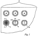
- a typical control panel assembly as generally indicated by reference numeral 10 includes a number of manual operator interface devices such a push button operator 14, a rotary selector 18 or a key operator 22. These operator interface devices manually interface with contact blocks which provide the means to control a number of output devices at locations remote from the control panel assembly 10. It is also common for the control panel assembly 10 to include a number of output devices such as pilot lights 26 which indicate the status of associated remotely located output devices controlled by the operator interface devices.
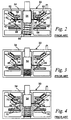
- a conventional contact block 30 of the prior art including a housing 34 enclosing a first set of spaced apart stationary contacts 38, a second set of spaced apart stationary contacts 42, a set of movable contacts 46 electrically connected together by a bridge 50 which is attached to a slidably movable shaft 54 and bussing 58 between the stationary contacts 38 and 42 and external electrical terminals 62.
- the slidable shaft 54 is normally biased to a first position by a spring 66 and manually movable to a second position. In the first position, the movable contacts 46 are in electrical contact with the first set of stationary contacts 38 thereby making them normally closed and therefore the second set of stationary contacts 42 are normally open.
- first and second stationary contacts, 38 and 42 are open.
- This type of contact block construction requires structural support components 70, integrally formed from portions of the inside of the contact block housing 34, for mounting and supporting the stationary electrical contacts 38 and 42 and the associated bussing 58 from those contacts to their associated external wiring terminals 62. Accordingly, making an integrated contact module of the present invention using this type of construction would require a significant increase in the housing size in order to enclose a printed circuit board with electrical components and the required electrical connections between the contacts, the printed circuit board and the external wiring terminals.
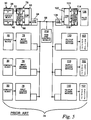
- FIG. 5 illustrates in block diagram form, a conventional manually actuatable contact block 30 and the components of a control panel system, generally indicated by reference numeral 74, to which the contact block 30 is connected.
- the system 74 generally includes a number of contact blocks 30, each having a first contact 38 and a second contact 42.
- the contact block 30 is electrically connected to an input access module 78 which includes a first logic circuit 82, a second logic circuit 86, a communications circuit 90 and a communications terminal 94 for connecting to a common communications link 98.
- a number of output devices 102 such as a pilot light 106, or other electrically controllable devices such as contactors and relays, each associated with a particular contact block 10 and input access module 58 are electrically connected to an associated output access module 110.
- Each output access module 110 includes a first logic circuit 114, a second logic circuit 118, a communications circuit 122 and a communications terminal 126 for connecting to the common communications link 98.
- the electrical connection between each contact block 30 and its associated input access module 78 and between each output access module 110 and its associated output device 102 must be hard wired by the panel assembler. It should be noted that since two logic circuits are included in each output access module 110, two output devices 106 can be controlled by a single output access module 110.
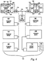
- FIG. 6 illustrates in block diagram form, a manually actuatable integrated contact block 150 constructed in accordance with the present invention and the components of a control panel system, generally indicated by reference numeral 154, to which the integrated contact block 150 is connected.
- the system 154 generally includes a number of integrated contact modules 150, each having a first contact 158, a logic circuit 162, a communications circuit 166 and a communications terminal 170 for connecting to a common communications link 174.
- the integrated contact modules 150 preferably include a second contact 178 and a second logic circuit 182.
- a number of output devices 102 such as pilot lights, contactors, relays or other electrically controllable devices, each associated with a particular integrated contact module 150 are electrically connected to an associated output control module 110 as described above.
- an integrated pilot light module 186 can be used to further reduce control panel wiring and assembly time.
- the integrated pilot light module 186 includes a communications terminal 190, a communications circuit 194, a logic circuit 198, an output switch 202 and a pilot light 204.
- the communications terminal 190, communications circuit 194, logic circuit 198, and output switch 202 can also be integrated into other electrically controllable output devices such as contactors or relays to form integrated output devices 208. These integrated output devices 208 eliminate the need for hard wiring between an output access module 110 and its associated output device 102.
- the system as described above can be used in either a time division multiplexed system or a network signaling control system.
- a communications link control module 212 can be required to provide the clock timing circuit for the system.
- the communications link control module 212 can also be programmed to place the system 154 in either the STAND-ALONE mode or the HOST mode.
- the logic circuits and communications circuits are software programmable to operate at a particular address, form simple logic functions and to operate in either the STAND-ALONE mode or the HOST mode.
- a communications control module 212 is not required.
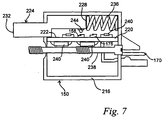
- the integrated contact block 150 includes a housing 216 which encloses and protects a printed circuit board 220 which has a first generally flat side 222.
- the first and second contacts, 158 and 178 respectively, are mounted on the first side 22 such that one is spaced apart from the other.
- the first and second logic circuits, 162 and 182 respectively, the communications circuit 166 and the communications terminal 170 are also mounted on the printed circuit board 220.
- a contact operator 224 is partially enclosed within the housing 216 such that a first end 228 in enclosed within the housing 216 and a second end 232 extends outside the housing 216.
- the contact operator 224 is slidably mounted such that it is moveable between a first position and a second position.
- the first end 228 is spaced apart from the first surface 221 such that it moves in a plane generally parallel to the first surface 221 as the contact operator 224 is moved between its first and second positions.
- the contact operator 224 is normally biased to the first position by a spring 236 and moved to the second position by manually moving the second end 232.
- the electrical and mechanical components contained within the housing 216 must be very small.
- the printed circuit board 220 is two sided board having a second generally flat side 238 on which other electrical components 240 such as integrated circuits, resistors, etc. can be mounted to conserve space.
- the first and second contacts, 158 and 178 respectively, are normally open miniature reed switches such as catalog number MITI-3 manufactured by Hamlin. These contacts 158 and 178 are operated by a small permanent magnet 244 such as catalog number 27941 manufactured by Arnold Engineering Company. The magnet 244 is fixedly attached to the contact operator at a point near its first end 122.
- the logic and communications circuits are implemented in an application specific integrated circuit or ASIC.
- the communications terminal 170 is of the modular type for mounting on a printed circuit board such as catalog number MLAS100-5-C manufactured by Panduit.
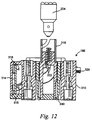
- the control panel assembly 10 includes a cover 246 having holes 250 through which the operator interface devices are mounted.
- the push button operator 14 will be used to illustrate the control panel assembly steps and operation.
- the cover 246 is generally flat and has an outside surface 254 and an inside surface 258.
- the hole 250 provides a means of communication between the outside surface 168 and the inside surface 258 such that operator interface devices can be installed on the cover 246.
- a push button operator assembly 262 includes a housing 266 having a push button end 270 and a contact block end 274, a plunger 278 slidably mounted inside the housing 266 having a push button end 282 and an operator surface 286.
- the push button end 270 of the housing 266 is dimensioned to pass through the hole 250 while the contact block end 274 is larger that the hole 250 and therefore cannot pass through.
- the push button operator assembly 262 is attached to the cover 246 by passing the push button end 270 through the hole 250 from the inside surface 258 such that it extends outward past the outside surface 254.
- the contact block end 274 of the housing 266 presses against a sealing washer 290 placed between the inside surface 258 of the cover 246 and the contact block end 274 of the housing 266.
- An anti-twist washer 294 is slidably received over the push button end 270 of the housing 266 such that it engages the cover 246.
- a retaining bushing 298 is then threadably received over the push button end 270 of the housing 266, thereby tightly clamping the cover 246 between the anti-twist washer 294 and bushing 298 on the outside surface 254 and the sealing washer 290 and contact block end 274 of the housing 266 on the inside surface 258.
- the push button assembly 262 is securely attached to the cover 246 of the control panel assembly 10.
- the integrated contact module 150 is now positioned against the contact block end 274 of the housing 266 such that the second end 232 of the contact operator 224 is in close proximity with the operator surface 286 of the plunger 278 and then attached to the housing 266 by a screw 302.
- the common communications link 174 is then connected to the integrated contact module 150 at the communications terminal 170 thereby completing the installation of the push button operator assembly 262 and the integrated contact module 150.
- the plunger 278 is normally biased to a first position by a spring 306.
- the contact operator 224 is also in its normally biased first position wherein the magnet 244 on the contact operator 224 is positioned immediately adjacent the first contact 158, thereby causing the first contact 158 to be in a closed condition.
- the plunger 278 moves toward a second position thereby causing the operator surface 286 to engage the second end 232 of the contact operator 224 causing it to move from its normally biased position toward its second position.
- the magnet is between the first and second contacts, 158 and 178 respectively, thereby allowing both contacts to be in their normally open condition.
- the plunger 278 and contact operator 224 reach their second position.
- a second integrated contact block 150 can be attached to the push button operator assembly 262 or other operator interface device as shown in Fig. 10.
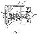
- the integrated pilot light module 186 also includes a housing 310 which encloses a printed circuit board 314 on which the communications terminal 190, communications circuit 194, logic circuit 198, and output switch 202 are attached and in communication with one another.
- the circuit board 314 is two sided such that electrical components 316 such as integrated circuits resistors and transistors can be mounted on both sides to conserve space within the housing 310.
- the output switch 202 is preferably a switching transistor or relay and is in electrical communication with the pilot light 204 such that it can be turned ON or OFF in response to a signal from the logic circuit 198.
- the integrated pilot light module 186 preferably incorporates a miniature bayonet base 318 for receiving the pilot light 204.
- the base is attached to the housing 310 such that terminals 322 pass through the housing 310 thereby providing a means for electrically connecting the pilot light 204 to the output switch 202.
- the pilot light 204 can be either a commercially available LED module having a bayonet base or a low voltage incandescent light having a bayonet base. When an LED module is used, no external power source is required; however, the low voltage incandescent light requires a pair of external power terminals 326 which are in electrical communication with the output switch 202 on the printed circuit board 314 such that the output switch 202 controls the power supplied to the pilot light 204.
- the integrate pilot light module 186 can be attached to a pilot light lens assembly, shown in Fig. 1, or to an illuminated operator interface device.
- a translation pin 330 passes through the pilot light housing 310 to communicate the manual movement of the operator interface device to a conventional contact block 30 or integrated contact module 150 which can be attached to the back of the pilot light 186.
Landscapes
- Selective Calling Equipment (AREA)
- Programmable Controllers (AREA)
- Push-Button Switches (AREA)
- Saccharide Compounds (AREA)
- Electrotherapy Devices (AREA)
- Feedback Control In General (AREA)
- Coupling Device And Connection With Printed Circuit (AREA)
Claims (37)
- Verfahren zur Herstellung einer manuellen Schalttafel (10) mit einem Modul (150), das einen manuell bedienbaren elektrischen Kontakt (158) und einen elektrischen Übertragungsanschluß (170) umfasst, der mit dem Kontakt (158) elektrisch in Verbindung steht, und einer manuell bedienbaren Betätigungselement-Schnittstellenvorrichtung (262), die an einer Schalttafel (246) befestigt ist und zum manuellen Bedienen des elektrischen Kontakts (158) dient, wobei elektrische Übertragungsmittel (174) an dem Übertragungsanschluß (170) angeschlossen sind, um ein elektrisches Signal an eine entfernt von der Schalttafel (246) angeordnete Ausgangsvorrichtung (102) zu übermitteln, gekennzeichnet durch folgende Schritte:Vormontieren des manuell bedienbaren elektrischen Kontakts (158) und eines zugehörigen Betätigungselements (224) in Verbindung mit einem Eingangsmodul, umfassend einen Logikschaltkreis (162), einen Übertragungsschaltkreis (166) und den Übertragungsanschluß (170), um ein IC-Eingangsmodul (150) zu bilden;Anbringen des IC-Eingangsmoduls (150) an der Betätigungselement-Schnittstellenvorrichtung (262), so dass die Betätigungselement-Schnittstellenvorrichtung (262) mit dem Kontakt-Betätigungselement (224) zusammenwirkt und Anschliessen des IC-Eingangsmodul (150) an eine gemeinsame Übertragungsverbindung (174) an der Schalttafel (246), um mit einem von der Schalttafel (246) entfernt angeordneten Ausgangsmodul (110) zu kommunizieren, um eine zugehörige Ausgangsvorrichtung (102) nach manueller Betätigung des Kontakt-Betätigungselements (224) durch die Betätigungselement-Schnittstellenvorrichtung (262) zu steuern.
- Verfahren nach Anspruch 1,
dadurch gekennzeichnet, dass
das vorherige Anordnen folgende Schritte umfaßt:Montieren des manuell bedienbaren elektrischen Kontakts (158) auf einer Platine (220);Montieren des Übertragungsschaltkreises (166), des Logikschaltkreises (162) und des Übertragungsanschlusses (170) des Eingangsmoduls auf der Platine (220), wobei die Platine (220) eine elektrische Übertragung zwischen dem Kontakt (158) und dem Logikschaltkreis (162), zwischen dem Logikschaltkreis (162) und dem Übertragungsschaltkreis (166) und zwischen dem Übertragungsschaltkreis (166) und dem Übertragungsanschluß (170) ermöglicht. - Verfahren nach Anspruch 2,
dadurch gekennzeichnet, dass
das vorherige Anordnen folgende weitere Schritte umfaßt:Montieren eines zweiten manuell bedienbaren elektrischen Kontakts (178) und eines zweiten Logikschaltkreises (182), der dem zweiten Kontakt (178) auf der Platine (220) zugeordnet ist, wobei die Platine (220) eine elektrische Übertragung zwischen dem zweiten elektrischen Kontakt (178) und dem zweiten Logikschaltkreis (182) und zwischen dem zweiten Logikschaltkreis (182) und dem Übertragungsschaltkreis (170) ermöglicht. - Verfahren nach Anspruch 2 oder 3,
dadurch gekennzeichnet, dass
das vorherige Anordnen folgende Schritte umfaßt:Montieren der Platine (220) innerhalb eines Schutzgehäuses (216); undverschiebbares Befestigen eines Kontakt-Betätigungselements (224) teilweise innerhalb des Gehäuses (216), so dass das Kontakt-Betätigungselement (224) in und aus einer Kontakt-Betätigungsposition bewegt werden kann. - Verfahren nach einem der vorhergehenden Ansprüche,
dadurch gekennzeichnet, dass
das Montieren folgende Schritte umfaßt:Montieren einer Betätigungselement-Schnittstellenvorrichtung (262) an einer Seite der Schalttafel; undAnbringen des IC-Eingangsmoduls (150) an der Betätigungselement-Schnittstellenvorrichtung (262) an einer der Schalttafel gegenüberliegenden Seite, so dass sie miteinander in Verbindung stehen. - Verfahren nach einem der vorhergehenden Ansprüche,
dadurch gekennzeichnet, dass
das Verbinden folgenden Schritt umfaßt:Anbringen eines Steckers oder einer gemeinsamen Übertragungsverbindung (174) an dem Übertragungsanschluß (170). - Verfahren nach einem der vorhergehenden Ansprüche,
gekennzeichnet durch dasMontieren mehrerer Betätigungselement-Schnittstellenvorrichtungen (262) an der Schalttafel; undAnbringen mehrerer vormontierter IC-Eingangsmodule (150) an den Betätigungselement-Schnittstellenvorrichtungen (262) und Verbinden jedes IC-Eingangsmoduls (150) durch die gemeinsame Übertragungsverbindung (172) mit mehreren zugeordneten Ausgangsmodulen (110). - Verfahren nach einem der vorhergehenden Ansprüche,
dadurch gekennzeichnet, dassdas Vormontieren mehrere Schritte umfaßt, einschließlich das Vormontieren des manuell betätigbaren IC-Eingangsmoduls (150) mit einem Mulitplex-Übertragungsschaltkreis zum Übertragen von Steuersignalen als Antwort auf das Einstellen des manuell bedienbaren elektrischen Kontakts (158) an ein Ausgangsmodul (110) im Zeitmultiplexverfahren. - Verfahren nach einem der vorhergehenden Ansprüche,
dadurch gekennzeichnet, dassdas Vormontieren mehrere Schritte umfaßt, einschließlich das Vormontieren des manuell betätigbaren IC-Eingangsmoduls (150) mit einem Signalübertragungs-Kodierschaltkreis zum Übertragen kodierter Steuersignale als Antwort auf das Einstellen des manuell bedienbaren elektrischen Kontakts (158) an ein Ausgangsmodul (110) durch Signalübertragung im Netzwerk. - Verfahren nach einem der vorhergehenden Ansprüche,
dadurch gekennzeichnet, dassdas Ausgangsmodul (110) mit der zugeordneten Ausgangsvorrichtung (202, 204) verbunden ist, um ein IC-Ausgangsmodul (186) zu bilden. - Verfahren nach Anspruch 1,
dadurch gekennzeichnet, dassdie Übertragungsverbindung (174) zur Übertragung von Steuersignalen als Antwort auf das Einstellen des manuell betätigbaren elektrischen Kontakts (158) des IC-Eingangsmoduls (150) an ein IC-Ausgangsmodul (186) zusätzlich zu dem von der Schalttafel (246) beabstandet angeordneten Ausgangsmodul (110) dient. - IC-Eingangs-/Ausgangsmodul (150, 186), umfassend eine Platine (220, 314) mit einer darauf befestigten Eingangs- oder Ausgangsvorrichtung (158) und einem Übertragungsanschluß (170), der mit der Eingangs- oder Ausgangsvorrichtung (158) elektrisch verbunden ist, wobei eine Übertragungsverbindung (174) mit dem Anschluß (170) verbunden ist, um ein Steuersignal an eine Ausgangsvorrichtung (102) zu übermitteln,
dadurch gekennzeichnet, dass
das Modul umfaßt:Ein Gehäuse (216) mit einem inneren Hohlraum;die Platine (220, 314), die innerhalb des Gehäuses montiert ist;die Eingangsvorrichtung (158) oder die Ausgangsvorrichtung (202, 204), die auf der Platine (230, 314) montiert ist;den Übertragungsanschluß (170, 190), der auf der Platine (220, 314) montiert ist und den Zugang zu einer Übertragungsverbindung (174) ermöglicht, wobei die Übertragungsverbindung (174) mehreren an die Übertragungsverbindung (174) angeschlossenen IC-Eingangs-/Ausgangsmodulen (150, 186) gemeinsam ist und die Übertragung zwischen diesen ermöglicht;einen Übertragungsschaltkreis (160, 194), der auf der Platine (220, 314) montiert ist, um Signale an andere Eingangs- oder Ausgangsmodule (150, 186) oder an die Ausgangsvorrichtung (186) und den Übertragungsschaltkreis (166, 194) zu senden, so dass eine Logikfunktion, die sich aus dem Zustand der Eingangsvorrichtung ableitet, an den Übertragungsschaltkreis (166, 194) geleitet werden kann, um auf die Übertragungsverbindung (174) ausgegeben zu werden; undeinen ersten Logikschaltkreis (162, 198), der auf der Platine (220, 314) montiert ist und mit der Eingangsvorrichtung (158) oder der Ausgangsvorrichtung (202, 204) und dem Übertragungsschaltkreis (166, 194) in Verbindung steht, so dass eine Logikfunktion, die sich aus dem Zustand der Eingangsvorrichtung (158) ableitet, an den Übertragungsschaltkreis (166) geleitet werden kann, um an die Übertragungsverbindung (174) ausgegeben zu werden, oder dass eine Logikfunktion, die sich aus einem Steuersignal ableitet, das über die Übertragungsverbindung (174) empfangen wurde, auf die Ausgangsvorrichtung (202, 204) angewendet werden kann. - Modul nach Anspruch 12,
dadurch gekennzeichnet, dassdie Platine (220, 314) zweiseitig ist und elektrische Komponenten sowohl auf der ersten als auch auf der zweiten im wesentlichen flachen Seite (222, 238) der Platine (220) montiert sind. - Modul nach Anspruch 12 oder 13,
dadurch gekennzeichnet, dassder Übertragungsschaltkreis (166) Nachrichtensignale zur Verwendung auf einer Übertragungsverbindung eines kodierten Netzwerks erzeugen kann. - Modul nach einem der Ansprüche 12 bis 14,
dadurch gekennzeichnet, dassdie Eingangsvorrichtung vorgesehen ist und das Modul ferner ein Kontakt-Betätigungselement (224) umfaßt, das teilweise innerhalb des Gehäuses (216) angeordnet und zwischen einer ersten Position und einer zweiten Position verschiebbar ist, um die Eingangsvorrichtung (158) zu betätigen. - Modul nach Anspruch 15,
dadurch gekennzeichnet, dassdie Eingangsvorrichtung einen ersten elektrischen Kontakt (158) umfaßt, der auf der Platine (220) befestigt ist, so dass die Bewegung des Kontakt-Betätigungselements (224) zwischen der ersten und der zweiten Position den Zustand des elektrischen Kontakts (158) ändert. - Modul nach Anspruch 15 oder 16,
dadurch gekennzeichnet, dass
das Kontakt-Betätigungselement (224) ferner umfaßt:Ein erstes in dem Gehäuse (216) angeordnetes Ende (228), wobei das erste Ende (228) von der ersten im wesentlichen flachen Seite (222) der Platine (220) beabstandet und im wesentlichen parallel dazu verschiebbar ist;ein zweites Ende (232), das sich aus dem Gehäuse (216) heraus erstreckt; undeinen Magneten (244), der an dem Kontakt-Betätigungselement (224) an einem Punkt in der Nähe des ersten Endes (228) befestigt ist, wobei der Magnet (244) nahe der ersten im wesentlichen flachen Seite (222) der Platine angeordnet ist, so dass er im wesentlichen parallel zu der ersten im wesentlichen flachen Seite (222) der Platine (220) bewegt werden kann, wenn das Kontakt-Betätigungselement (224) zwischen der ersten und zweiten Position hin und her bewegt wird. - Modul nach Anspruch 16,
dadurch gekennzeichnet, dassder erste elektrische Kontakt (158) ein Reedschalter ist. - Modul nach Anspruch 17 in Verbindung mit Anspruch 16,
dadurch gekennzeichnet, dassdas Kontakt-Betätigungselement (224) im Ruhezustand in der ersten Position vorgespannt ist, wobei der Magnet (244) unmittelbar an den ersten Kontakt (158) angrenzt, wodurch der erste Kontakt (158) geschlossen wird. - Modul nach Anspruch 19,
dadurch gekennzeichnet, dassder Magnet (244) in der zweiten Position ausreichend weit von dem ersten Kontakt (158) wegbewegt wird, wodurch der erste Kontakt (158) geöffnet wird. - Modul nach Anspruch 20,
dadurch gekennzeichnet, dassein zweiter elektrischer Kontakt (178) auf der ersten im wesentlichen flachen Seite (222) der Platine (220) befestigt ist, so dass die Bewegung des Kontakt-Betätigungselements (224) zwischen der ersten und der zweiten Position eine Zustandsänderung des zweiten elektrischen Kontakts (178) bewirkt, wobei der zweite elektrische Kontakt (178) von dem ersten elektrischen Kontakt (158) beabstandet ist. - Modul nach Anspruch 21,
dadurch gekennzeichnet, dassder zweite elektrische Kontakt (178) ein Reedschalter ist. - Modul nach Anspruch 21 oder 22,
dadurch gekennzeichnet, dassein zweiter Logikschaltkreis (182) auf der Platine (220) befestigt ist und mit dem zweiten elektrischen Kontakt (178) in Verbindung steht, so dass eine Logikfunktion als Antwort auf die Zustandsänderung des zweiten elektrischen Kontakts (177) erzeugt werden kann, wobei der zweite Logikschaltkreis (182) mit dem Übertragungsschaltkreis (166) in Verbindung steht. - Modul nach Anspruch 21,
dadurch gekennzeichnet, dassdas Kontakt-Betätigungselement (224) im Ruhezustand in der ersten Position vorgespannt ist, wobei der Magnet (244) unmittelbar an den ersten Kontakt (158) angrenzt, wodurch der erste Kontakt (158) geschlossen ist, und ausreichend weit von dem zweiten Kontakt (178) weg ist, wodurch der zweite Kontakt (178) geöffnet wird. - Modul nach Anspruch 24,
dadurch gekennzeichnet, dassder Magnet (244) in der zweiten Position ausreichend weit von dem ersten Kontakt (158) wegbewegt wird, wodurch der erste Kontakt (158) geöffnet wird, wobei der Magnet unmittelbar an den zweiten Kontakt (178) angrenzt, wodurch der zweite Kontakt (178) geschlossen wird. - Modul nach Anspruch 25,
dadurch gekennzeichnet, dassder Magnet in einer Zwischenposition zwischen der ersten und zweiten Position ausreichend weit sowohl von dem ersten als auch von dem zweiten Kontakt (158, 178) weg ist, wodurch sowohl der erste als auch der zweite Kontakt (158, 178) geöffnet werden. - Modul nach einem der Ansprüche 12 bis 26,
dadurch gekennzeichnet, dassdie Ausgangsvorrichtung einen Ausgangsschalter (202) umfaßt, der auf der Platine (314) montiert ist und mit dem Logikschaltkreis (198) in Verbindung steht, so dass der Zustand des Ausgangsschalters (202) in Reaktion auf die Logikfunktion geändert werden kann, die auf das von dem Übertragungsschaltkreis (194) empfangene und interpretierte Steuersignal von der Übertrtagungsverbindung (174) angewendet wird. - Modul nach Anspruch 27,
dadurch gekennzeichnet, dassdie Ausgangsvorrichtung (102) eine Signallampe (204) ist, deren EIN- AUS-Zustand durch die Stellung des Ausgangsschalters (202) bestimmt wird, der das Zuleiten oder Sperren von Strom zu der Signallampe (204) steuert. - Modul nach Anspruch 28,
dadurch gekennzeichnet, dassdie Signallampe (204) eine LED ist. - Modul nach Anspruch 28,
dadurch gekennzeichnet, dassdie Signallampe (204) eine Niedervolt-Glühlampe ist. - Modul nach Anspruch 12,
dadurch gekennzeichnet, dassder Ausgangsschalter ein Schalttransistor ist. - Modul nach Anspruch 12,
dadurch gekennzeichnet, dassdie Ausgangsvorrichtung (102) ein elektronisches Relais. - Modul nach Anspruch 12,
dadurch gekennzeichnet, dassdie Ausgangsvorrichtung (102) ein Relais ist. - Modul nach Anspruch 12,
dadurch gekennzeichnet, dassdie Ausgangsvorrichtung (102) ein Taster ist. - Modul nach einem der Ansprüche 12 bis 34 in Verbindung mit einer Schalttafel (246), wobei die Schalttafel (246) eine Betätigungsvorrichtung (262) aufweist, die mit der Eingangsvorrichtung zum wahlweisen betätigen der Eingangsvorrichtung (158) zusammenwirkt.
- Modul nach Anspruch 35,
dadurch gekennzeichnet, dassdie Ausgangsvorrichtung (102) von der Schalttafel (246) beabstandet angeordnet ist. - Modul nach Anspruch 35 oder 36,
dadurch gekennzeichnet, dassdie Betätigungsvorrichtung (262) einen manuell bedienbaren Knopf (278) umfaßt.
Applications Claiming Priority (3)
| Application Number | Priority Date | Filing Date | Title |
|---|---|---|---|
| US282839 | 1994-07-29 | ||
| US08/282,839 US5525846A (en) | 1994-08-27 | 1994-08-27 | Manually actuatable integrated control module and method of making same |
| PCT/US1995/009222 WO1996007190A1 (en) | 1994-07-29 | 1995-07-21 | Manually actuatable integrated control module and method of making same |
Publications (2)
| Publication Number | Publication Date |
|---|---|
| EP0740843A1 EP0740843A1 (de) | 1996-11-06 |
| EP0740843B1 true EP0740843B1 (de) | 2000-05-10 |
Family
ID=23083347
Family Applications (1)
| Application Number | Title | Priority Date | Filing Date |
|---|---|---|---|
| EP95927338A Revoked EP0740843B1 (de) | 1994-07-29 | 1995-07-21 | Handbetätigtes integriertes steuermodul und verfahren zu seiner herstellung |
Country Status (7)
| Country | Link |
|---|---|
| US (1) | US5525846A (de) |
| EP (1) | EP0740843B1 (de) |
| AU (1) | AU688947B2 (de) |
| CA (1) | CA2181039C (de) |
| DE (1) | DE69516846T2 (de) |
| ES (1) | ES2149369T3 (de) |
| WO (1) | WO1996007190A1 (de) |
Families Citing this family (9)
| Publication number | Priority date | Publication date | Assignee | Title |
|---|---|---|---|---|
| US5971597A (en) | 1995-03-29 | 1999-10-26 | Hubbell Corporation | Multifunction sensor and network sensor system |
| US5772326A (en) * | 1996-08-30 | 1998-06-30 | Hubbell Incorporated | Temperature and passive infrared sensor module |
| US5764146A (en) * | 1995-03-29 | 1998-06-09 | Hubbell Incorporated | Multifunction occupancy sensor |
| US5973594A (en) * | 1995-03-29 | 1999-10-26 | Hubbell Incorporated | Multiple optical designs for a multifunction sensor |
| US5682259A (en) * | 1996-03-19 | 1997-10-28 | Square D Company | Bus powered manually actuatable integrated pilot light/contact/communications module |
| DE29813501U1 (de) | 1998-07-29 | 1998-11-05 | Gebr. Berker GmbH & Co, 58579 Schalksmühle | Betätigungshilfen an einem elektrischen Installationswippenschalter und an einem Drucktastenschalter für den bestimmungsgemäßen Gebrauch der Schalter für körperbehinderte Menschen |
| US8279029B2 (en) * | 2008-07-10 | 2012-10-02 | Flextronics Automotive, Inc. | Weatherproof switch for indoor and outdoor information clusters and function switches |
| SE539937C2 (en) * | 2015-01-09 | 2018-01-30 | Carlsson Leif | Bus Powered Manually Actuable Contact and Communication Module |
| CN108679785B (zh) * | 2018-05-31 | 2024-06-14 | 南京誉泰瑞思科技有限公司 | 多路空调控制器 |
Family Cites Families (9)
| Publication number | Priority date | Publication date | Assignee | Title |
|---|---|---|---|---|
| US3243544A (en) * | 1964-12-09 | 1966-03-29 | Allen Bradley Co | Convertible relay control station |
| US3770925A (en) * | 1972-07-10 | 1973-11-06 | Allen Bradley Co | Switch mounting structure |
| US4306123A (en) * | 1979-02-21 | 1981-12-15 | Taylor Glenn R | Contact block |
| JPH073465B2 (ja) * | 1986-09-12 | 1995-01-18 | オムロン株式会社 | スイツチ機構 |
| US5146615A (en) * | 1989-08-07 | 1992-09-08 | Ericsson Ge Mobile Communications Holding Inc. | Interchangeable control panels and keypads for radio transceivers and related process |
| US5074798A (en) * | 1989-10-24 | 1991-12-24 | Wells Electronics, Inc. | Modular socket for an integrated circuit |
| US5155664A (en) * | 1990-12-28 | 1992-10-13 | Square D Company | Operator interface panel assembly for use with a programmable logic controller |
| US5290983A (en) * | 1991-08-02 | 1994-03-01 | The Whitaker Corporation | Wall switch |
| US5426564A (en) * | 1991-09-30 | 1995-06-20 | Hsu; Winston | Modular electronic packaging |
-
1994
- 1994-08-27 US US08/282,839 patent/US5525846A/en not_active Expired - Lifetime
-
1995
- 1995-07-21 WO PCT/US1995/009222 patent/WO1996007190A1/en not_active Ceased
- 1995-07-21 DE DE69516846T patent/DE69516846T2/de not_active Revoked
- 1995-07-21 CA CA002181039A patent/CA2181039C/en not_active Expired - Fee Related
- 1995-07-21 EP EP95927338A patent/EP0740843B1/de not_active Revoked
- 1995-07-21 AU AU31396/95A patent/AU688947B2/en not_active Ceased
- 1995-07-21 ES ES95927338T patent/ES2149369T3/es not_active Expired - Lifetime
Also Published As
| Publication number | Publication date |
|---|---|
| ES2149369T3 (es) | 2000-11-01 |
| MX9601595A (es) | 1998-07-31 |
| US5525846A (en) | 1996-06-11 |
| WO1996007190A1 (en) | 1996-03-07 |
| CA2181039C (en) | 2005-09-13 |
| AU3139695A (en) | 1996-03-22 |
| EP0740843A1 (de) | 1996-11-06 |
| DE69516846D1 (de) | 2000-06-15 |
| CA2181039A1 (en) | 1996-03-07 |
| DE69516846T2 (de) | 2000-12-28 |
| AU688947B2 (en) | 1998-03-19 |
Similar Documents
| Publication | Publication Date | Title |
|---|---|---|
| CA2122989C (en) | Intelligent lamp or intelligent contact terminal for a lamp | |
| EP0740843B1 (de) | Handbetätigtes integriertes steuermodul und verfahren zu seiner herstellung | |
| AU713672B2 (en) | Bus powered manually actuatable integrated pilot light/contact/communications module | |
| EP0337751A3 (de) | Sicherungssystem | |
| US5155664A (en) | Operator interface panel assembly for use with a programmable logic controller | |
| EP1551047A2 (de) | Digitales Erwachungssignal aus Analogsignalübergang | |
| ATE283178T1 (de) | Batterie-trennvorrichtung | |
| MXPA96001595A (en) | Manually actuatable integrated control module and method of making same | |
| US6127748A (en) | Installation for making electrical connection between an equipment assembly and a command and control system | |
| EP0734602A1 (de) | Signalanzeigende vorrichtung | |
| SE539937C2 (en) | Bus Powered Manually Actuable Contact and Communication Module | |
| EP1551046B1 (de) | Digitales Erwachungssignal aus Schaltübergang von zwei Analogsignalen | |
| KR100267804B1 (ko) | 미터 구동장치 | |
| US11215348B2 (en) | Luminaire, arrangement, particularly door contact switch, circuit board and use | |
| WO1998025796A1 (en) | Emergency signalling apparatus for vehicles | |
| MXPA97008473A (es) | Modulo de luz piloto/contactos/comunicacionesintegrado, accionable manualmente, activado enbarra conectora | |
| JPH0739034Y2 (ja) | 警報システム | |
| US3486151A (en) | Switch assembly | |
| EP0774380B1 (de) | Elektrische Verdrahtungseinrichtung zur Kontrolle von Fahrzeugsnotlichten | |
| IT202300010869A1 (it) | Gruppo modulare di comando per un sistema domotico | |
| EP0911221A2 (de) | Im Kraftfahrzeug eingebautes Multiplexübertragungssystem | |
| JPH09232086A (ja) | 記名条片照明電球切換装置 | |
| JPH02276174A (ja) | Hdlcループコネクタ | |
| JPH11325561A (ja) | ファンコイルシステム |
Legal Events
| Date | Code | Title | Description |
|---|---|---|---|
| PUAI | Public reference made under article 153(3) epc to a published international application that has entered the european phase |
Free format text: ORIGINAL CODE: 0009012 |
|
| 17P | Request for examination filed |
Effective date: 19960520 |
|
| AK | Designated contracting states |
Kind code of ref document: A1 Designated state(s): CH DE ES FR GB IT LI |
|
| 17Q | First examination report despatched |
Effective date: 19970113 |
|
| GRAG | Despatch of communication of intention to grant |
Free format text: ORIGINAL CODE: EPIDOS AGRA |
|
| GRAH | Despatch of communication of intention to grant a patent |
Free format text: ORIGINAL CODE: EPIDOS IGRA |
|
| GRAG | Despatch of communication of intention to grant |
Free format text: ORIGINAL CODE: EPIDOS AGRA |
|
| GRAH | Despatch of communication of intention to grant a patent |
Free format text: ORIGINAL CODE: EPIDOS IGRA |
|
| GRAG | Despatch of communication of intention to grant |
Free format text: ORIGINAL CODE: EPIDOS AGRA |
|
| GRAG | Despatch of communication of intention to grant |
Free format text: ORIGINAL CODE: EPIDOS AGRA |
|
| GRAG | Despatch of communication of intention to grant |
Free format text: ORIGINAL CODE: EPIDOS AGRA |
|
| GRAH | Despatch of communication of intention to grant a patent |
Free format text: ORIGINAL CODE: EPIDOS IGRA |
|
| GRAH | Despatch of communication of intention to grant a patent |
Free format text: ORIGINAL CODE: EPIDOS IGRA |
|
| GRAA | (expected) grant |
Free format text: ORIGINAL CODE: 0009210 |
|
| AK | Designated contracting states |
Kind code of ref document: B1 Designated state(s): CH DE ES FR GB IT LI |
|
| REG | Reference to a national code |
Ref country code: CH Ref legal event code: EP |
|
| REF | Corresponds to: |
Ref document number: 69516846 Country of ref document: DE Date of ref document: 20000615 |
|
| ET | Fr: translation filed | ||
| ITF | It: translation for a ep patent filed | ||
| REG | Reference to a national code |
Ref country code: CH Ref legal event code: NV Representative=s name: BOVARD AG PATENTANWAELTE |
|
| REG | Reference to a national code |
Ref country code: ES Ref legal event code: FG2A Ref document number: 2149369 Country of ref document: ES Kind code of ref document: T3 |
|
| PLBI | Opposition filed |
Free format text: ORIGINAL CODE: 0009260 |
|
| PLBQ | Unpublished change to opponent data |
Free format text: ORIGINAL CODE: EPIDOS OPPO |
|
| PLBI | Opposition filed |
Free format text: ORIGINAL CODE: 0009260 |
|
| 26 | Opposition filed |
Opponent name: MOELLER GMBH Effective date: 20010203 |
|
| 26 | Opposition filed |
Opponent name: SIEMENS AG ZENTRALABTEILUNG TECHNIK ABTLG. ZT PA 1 Effective date: 20010209 Opponent name: PEPPERL + FUCHS GMBH Effective date: 20010211 Opponent name: IFM ELECTRONIC GMBH Effective date: 20010209 Opponent name: MOELLER GMBH Effective date: 20010203 |
|
| REG | Reference to a national code |
Ref country code: GB Ref legal event code: IF02 |
|
| PLBF | Reply of patent proprietor to notice(s) of opposition |
Free format text: ORIGINAL CODE: EPIDOS OBSO |
|
| PLBF | Reply of patent proprietor to notice(s) of opposition |
Free format text: ORIGINAL CODE: EPIDOS OBSO |
|
| PLBF | Reply of patent proprietor to notice(s) of opposition |
Free format text: ORIGINAL CODE: EPIDOS OBSO |
|
| PLBF | Reply of patent proprietor to notice(s) of opposition |
Free format text: ORIGINAL CODE: EPIDOS OBSO |
|
| PLBF | Reply of patent proprietor to notice(s) of opposition |
Free format text: ORIGINAL CODE: EPIDOS OBSO |
|
| PLBF | Reply of patent proprietor to notice(s) of opposition |
Free format text: ORIGINAL CODE: EPIDOS OBSO |
|
| APBP | Date of receipt of notice of appeal recorded |
Free format text: ORIGINAL CODE: EPIDOSNNOA2O |
|
| APBQ | Date of receipt of statement of grounds of appeal recorded |
Free format text: ORIGINAL CODE: EPIDOSNNOA3O |
|
| APAA | Appeal reference recorded |
Free format text: ORIGINAL CODE: EPIDOS REFN |
|
| PGFP | Annual fee paid to national office [announced via postgrant information from national office to epo] |
Ref country code: FR Payment date: 20050706 Year of fee payment: 11 |
|
| PGFP | Annual fee paid to national office [announced via postgrant information from national office to epo] |
Ref country code: ES Payment date: 20050721 Year of fee payment: 11 |
|
| PGFP | Annual fee paid to national office [announced via postgrant information from national office to epo] |
Ref country code: DE Payment date: 20050729 Year of fee payment: 11 |
|
| PGFP | Annual fee paid to national office [announced via postgrant information from national office to epo] |
Ref country code: CH Payment date: 20050927 Year of fee payment: 11 |
|
| APAH | Appeal reference modified |
Free format text: ORIGINAL CODE: EPIDOSCREFNO |
|
| PGFP | Annual fee paid to national office [announced via postgrant information from national office to epo] |
Ref country code: GB Payment date: 20060614 Year of fee payment: 12 |
|
| APBU | Appeal procedure closed |
Free format text: ORIGINAL CODE: EPIDOSNNOA9O |
|
| RDAF | Communication despatched that patent is revoked |
Free format text: ORIGINAL CODE: EPIDOSNREV1 |
|
| RDAG | Patent revoked |
Free format text: ORIGINAL CODE: 0009271 |
|
| STAA | Information on the status of an ep patent application or granted ep patent |
Free format text: STATUS: PATENT REVOKED |
|
| PGFP | Annual fee paid to national office [announced via postgrant information from national office to epo] |
Ref country code: IT Payment date: 20060731 Year of fee payment: 12 |
|
| REG | Reference to a national code |
Ref country code: CH Ref legal event code: PL |
|
| 27W | Patent revoked |
Effective date: 20060517 |
|
| GBPC | Gb: european patent ceased through non-payment of renewal fee |
Effective date: 20060517 |
|
| PLAB | Opposition data, opponent's data or that of the opponent's representative modified |
Free format text: ORIGINAL CODE: 0009299OPPO |
|
| PLAB | Opposition data, opponent's data or that of the opponent's representative modified |
Free format text: ORIGINAL CODE: 0009299OPPO |