EP0740875B1 - Verfahren und system zur steuerung eines atm-busses - Google Patents
Verfahren und system zur steuerung eines atm-busses Download PDFInfo
- Publication number
- EP0740875B1 EP0740875B1 EP95905653A EP95905653A EP0740875B1 EP 0740875 B1 EP0740875 B1 EP 0740875B1 EP 95905653 A EP95905653 A EP 95905653A EP 95905653 A EP95905653 A EP 95905653A EP 0740875 B1 EP0740875 B1 EP 0740875B1
- Authority
- EP
- European Patent Office
- Prior art keywords
- bus
- address
- cell
- interface unit
- transmission
- Prior art date
- Legal status (The legal status is an assumption and is not a legal conclusion. Google has not performed a legal analysis and makes no representation as to the accuracy of the status listed.)
- Expired - Lifetime
Links
- 238000000034 method Methods 0.000 title claims abstract description 12
- 230000005540 biological transmission Effects 0.000 claims abstract description 43
- 230000003213 activating effect Effects 0.000 claims abstract description 4
- 230000004044 response Effects 0.000 claims 1
- 238000012913 prioritisation Methods 0.000 description 2
- 230000001419 dependent effect Effects 0.000 description 1
- 230000000630 rising effect Effects 0.000 description 1
- 239000002699 waste material Substances 0.000 description 1
Images
Classifications
-
- H—ELECTRICITY
- H04—ELECTRIC COMMUNICATION TECHNIQUE
- H04L—TRANSMISSION OF DIGITAL INFORMATION, e.g. TELEGRAPHIC COMMUNICATION
- H04L12/00—Data switching networks
- H04L12/28—Data switching networks characterised by path configuration, e.g. LAN [Local Area Networks] or WAN [Wide Area Networks]
- H04L12/40—Bus networks
- H04L12/40006—Architecture of a communication node
- H04L12/40013—Details regarding a bus controller
-
- H—ELECTRICITY
- H04—ELECTRIC COMMUNICATION TECHNIQUE
- H04L—TRANSMISSION OF DIGITAL INFORMATION, e.g. TELEGRAPHIC COMMUNICATION
- H04L12/00—Data switching networks
- H04L12/28—Data switching networks characterised by path configuration, e.g. LAN [Local Area Networks] or WAN [Wide Area Networks]
- H04L12/40—Bus networks
- H04L12/403—Bus networks with centralised control, e.g. polling
-
- H—ELECTRICITY
- H04—ELECTRIC COMMUNICATION TECHNIQUE
- H04Q—SELECTING
- H04Q11/00—Selecting arrangements for multiplex systems
- H04Q11/04—Selecting arrangements for multiplex systems for time-division multiplexing
- H04Q11/0428—Integrated services digital network, i.e. systems for transmission of different types of digitised signals, e.g. speech, data, telecentral, television signals
- H04Q11/0478—Provisions for broadband connections
-
- H—ELECTRICITY
- H04—ELECTRIC COMMUNICATION TECHNIQUE
- H04L—TRANSMISSION OF DIGITAL INFORMATION, e.g. TELEGRAPHIC COMMUNICATION
- H04L12/00—Data switching networks
- H04L12/54—Store-and-forward switching systems
- H04L12/56—Packet switching systems
- H04L12/5601—Transfer mode dependent, e.g. ATM
- H04L2012/5614—User Network Interface
- H04L2012/5615—Network termination, e.g. NT1, NT2, PBX
Definitions
- the invention relates to a method and system for controlling a statistically multiplexed ATM bus, to the bus being connected a bus controller and interface units for transmission of packets, i.e. cells, over the bus.
- the invention thus relates to a bus solution applicable to statistical multiplexing and demultiplexing of ATM cells from several interface cards.
- the interface rates are typically between 0 and 155 Mbit/s.
- ATM Asynchronous Transfer Mode
- data is transmitted in packets, i.e. cells, of 53 octets.
- One basic ATM rate at which these cells are transmitted and switched is 155 Mbit/s.
- the ATM cells generated by the interfaces must be multiplexed to this rate.
- EP-A-022 170 examples of prior art bus solutions are disclosed in EP-A-022 170, EP-A-0 354 119 and WO-A-9 107 031.
- Previously used bus solutions such as the SDH multiplexers of product family SYNFONET and the PCM buses of Nokia DX200, are based on time-shared operation of the bus, in which each interface is allocated a separate time slot. This is a waste of bus capacity and is not suitable to statistical multiplexing since bus capacity is assigned irrespective of transmission need. Because of this, concentration, i.e. serving of interfaces having a greater than nominal cell transmission rate, is impossible.
- the object of the present invention is to provide a method and system by which the above restrictions can be eliminated.
- the method of the invention is characterized in that after detecting, for each cell to be transmitted to an ATM bus, the address of the interface unit participating in the transmission, the bus controller sets the address on an address bus of the ATM bus, thereby activating the transmission of the cell from the bus controller to the interface unit or vice versa over a data bus of the ATM bus; and that during the transmission of the cell, the bus controller fetches the next interface unit address for transmission of the next cell from or to the interface unit concerned.
- the bus allocation in accordance with the invention enables the use of transmission capacity by only those interfaces that have an actual transmission need.
- the allocation method allows prioritization of interfaces and makes concentration possible by furnishing it with interface units having a transmission capacity of above e.g. 155 Mbit/s.
- Transmission capacity of a bus controlled as described in the invention is thus used in both uplink and downlink directions such that in both directions e.g. a single unit can take the whole transmission capacity if the other units do not have anything to transmit.
- the ATM bus of the invention is a 'point-to-multipoint' type bus with a transmission capacity of e.g. about 155 Mbit/s. Data is transmitted in cells of 53 octets. The start of a cell is indicated by a cell sync pulse, which occurs at 2.72 ⁇ s intervals.
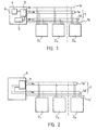
- the bus divides into a multiplexing ('uplink') and demultiplexing ('downlink') element, the multiplexing element being shown in Fig. 1 and the demultiplexing in Fig. 2.
- a multiplexing element 1 of the bus has its own data bus 1d and address bus 1a.
- Part 1c of the bus is for timing on the cell and bit level.
- the operation of the bus is controlled by a bus controller 6, multiplexer, provided with a microprocessor 5 and connected to an ATM switch by a 155 Mbit/s line.
- a bus controller 6 multiplexer, provided with a microprocessor 5 and connected to an ATM switch by a 155 Mbit/s line.
- To the bus is also connected a number of interface units 2 1 -2 N , which generate and/or receive ATM cells in accordance with their own transmission need and rate.
- the bus controller 6 allocates transmission periods to the interface units 2 1 -2 N by setting interface unit addresses from a RAM 3 of the controller on the address bus la.
- the controller scans the entire address space within the duration of one cell, which in this example (155 Mbit/s bus) is the above-mentioned 2.72 ⁇ s.
- An interface unit 2 X i.e. any one of units 2 1 -2 N , that has an ATM cell to transmit, sends a request-to-send signal lr to the bus controller 6, which stops a counter 4 that increments addresses in the RAM 3 at the corresponding memory location X, maintaining the address of the interface unit 2 X that sent the request-to-send signal on the address bus la.
- the interface unit that requested transmission receives permission to transmit its cell at the rising edge of the next cell sync pulse (bus signal 1c).
- the bus controller simultaneously continues the interrupted incrementing of addresses at the next memory location X+1. Those interface units which do not have anything to transmit do not react in any way to the contents of the address bus in the multiplexing direction.
- the next possible transmitter is looked for simultaneously as the cell of the interface unit 2 X that has been authorized to transmit is being transmitted.
- the interface units In the multiplexing direction, the interface units thus continuously 'listen' to the address bus la, but only an interface unit 2 X with a cell ready for transmission sends a request-to-send signal to the bus controller 6 when it detects its own address on the address bus.
- interface unit addresses in the memory locations of the RAM 3 can advantageously be given a different position in the allocation of the bus 1. If addresses of interface units are initialized in the memory in proportion to their transmission capacity, bus capacity can be allocated in a congestion in proportion to the transmission rate of the interface, i.e. the number of memory locations per interface unit in the memory of the bus controller is in proportion to the rate of each interface unit. For example, an 8 Mbit/s interface thus has 4 times as many addresses as a 2 Mbit/s interface.
- addresses of interface units stored in the memory 3 and located on the address bus may mean either addresses in a tabular memory or addresses stored in memory locations according to a rule.
- the address is in a register that is scanned address-by-address, one address at a time; in the second case, the address is fetched from a memory location. Even in the latter case, one memory location is scanned at a time, but not necessarily in the physical order; addresses can thus be prioritized without repeating the same addresses, e.g. by means of prioritization tests varying with the situation.
- the bus control according to the invention allows concentration of interface units, whereby the bus controller serves a larger number of interface units than the transmission capacity of the bus would allow if the interface units were used at full capacity.
- the bus controller 6 selects the address of the ATM cell to be transmitted to the receiver 2 1 -2 N on the basis of the cell header, the whole or part of the contents of the VPI/VCI field in the cell being used for indicating the memory location of the memory 3 where the bus address of the desired interface unit is located.
- the address thus obtained is taken to the address bus la' of the demultiplexing bus 1', and the original cell is taken to the data bus ld'.
- the multiplexing (Fig. 1) and demultiplexing transmission directions thus have their own address and data buses.
- the width and detailed timing of the bus are dependent on the technology available.
- the bus may either operate as a backplane bus for one multiplexer, or it may extend from one multiplexer to another.
- the clock of the bus should be less than 20 MHz (e.g. 19.4 MHz), which leads to 8-bit wide data buses.
- the width of the address bus depends on the number of units to be multiplexed, but the address space of the bus controller, the memory access rate, and the cell transmission frequency of the bus must be proportioned to one another so that the entire address space can be scanned between two cell sync pulses, i.e. in this example in less than 2.72 ⁇ s, by conducting a poll that covers the addresses of the interface units.
Landscapes
- Engineering & Computer Science (AREA)
- Computer Networks & Wireless Communication (AREA)
- Signal Processing (AREA)
- Data Exchanges In Wide-Area Networks (AREA)
- Small-Scale Networks (AREA)
- Selective Calling Equipment (AREA)
Claims (7)
- Verfahren zur Steuerung eines statistisch gemultiplexten ATM-Busses (1; 1'), wobei an den Bus ein Bus-Controller (6) und Schnittstelleneinheiten (21 bis 2N) zur Übertragung von Paketen, d.h. Zellen, über den Bus angeschlossen sind,
dadurch gekennzeichnet, dass
der Bus-Controller einen Speicher (3) zur Speicherung von Schnittstelleneinheitenadressen hat, und dass, nach dem Erfassen der Adresse der an der Übertragung teilnehmenden Schnittstelleneinheit, für jede zu dem ATM-Bus zu übertragende Zelle der Bus-Controller (6) die Adresse auf einen Adressbus (1a; 1a') des ATM-Busses (1; 1') einstellt, wodurch die Übertragung der Zelle von dem Bus-Controller zu der Schnittstelleneinheit über einen Datenbus (1d; 1d') des ATM-Busses aktiviert wird;
der Bus-Controller (6) während der Übertragung der Zelle die nächste Schnittstelleneinheit-Adresse zur Übertragung der nächsten Zelle von oder zu der betroffenen Schnittstelleneinheit abruft, wobei der Erfassungsschritt aufweist:der Bus-Controller (6) schaltet Adressen von Schnittstelleneinheiten (21 bis 2N) aus dem Speicher (3) auf den Adressbus (1a) weiter, wodurch eine Schnittstelleneinheit, die eine zur Übertragung bereitstehende Zelle hat, ein Sendeanforderungssignal an den Bus-Controller (6) sendet, wenn sie ihre eigene Adresse auf dem Adressbus erfasst. - Verfahren nach Anspruch 1, dadurch gekennzeichnet, dass der Bus-Controller (6) beim Demultiplexen gemultiplexter Zellen die Kennung der derzeitigen Schnittstelleneinheit aus dem Adressfeld der zu Schnittstelleneinheiten (21 bis 2N) zu übertragenden gemultiplexten Zellen ausliest.
- Verfahren nach Anspruch 1 oder 2, dadurch gekennzeichnet, dass Zellensynchronisationsimpulse auf dem ATM-Bus vorliegen, und dass der Adressraum des Bus-Controllers (6), die Speicherzugriffsrate und die Zellenübertragungsfrequenz des Busses derart zueinander bemessen sind, dass der gesamte Adressraum zwischen zwei Zellensynchronisationsimpulsen des Busses (1; 1') abgetastet werden kann, indem eine Abfrage durchgeführt wird, welche die Adressen der Schnittstelleneinheiten (21 bis 2N) umfasst.
- Verfahren nach einem der Ansprüche 1 bis 3, dadurch gekennzeichnet, dass die Anzahl von Speicherorten pro Schnittstelleneinheit in dem Speicher (3) des Bus-Controllers (6) nach der Übertragungskapazität jeder Schnittstelleneinheit (21 bis 2N) bemessen ist.
- Verfahren nach einem der Ansprüche 1 bis 3, dadurch gekennzeichnet, dass die Anzahl von Speicherorten pro Schnittstelleneinheit in dem Speicher (3) des Bus-Controllers (6) nach dem Prioritätsniveau jeder Schnittstelleneinheit (21 bis 2N) bemessen ist.
- System zur Steuerung eines statistisch gemultiplexten ATM-Busses, wobei das System einen Bus-Controller (6) aufweist, der Pakete, d.h. Zellen, über den Bus (1;1') überträgt, und an den Controller mittels des Busses angeschlossene Schnittstelleneinheiten (21 bis 2N) aufweist,
dadurch gekennzeichnet, dass
der Bus-Controller (6) Einrichtungen aufweist, um nach dem Erfassen der Adresse der an der Übertragung teilnehmenden Schnittstelleneinheit, für jede zu dem ATM-Bus zu übertragende Zelle, die Adresse der Schnittstelleneinheit auf einen Adressbus (1a; 1a') des ATM-Busses (1;1') einstellt, wodurch die Übertragung der Zelle von dem Bus-Controller zu der Schnittstelleneinheit über einen Datenbus (1d; 1d') des ATM-Busses aktiviert wird;
der Bus-Controller (6) Einrichtungen aufweist, um während der Übertragung der Zelle die nächste Schnittstelleneinheit-Adresse zur Übertragung der nächsten Zelle von oder zu der betroffenen Schnittstelleneinheit abzurufen;
der Bus-Controller (6) Einrichtungen aufweist, um Adressen von Schnittstelleneinheiten (21 bis 2N) aus einem Speicher (3) auf den Adressbus (1a) weiterzuschalten, und
jede Schnittstelleneinheit angepasst ist, um im Ansprechen auf das Erfassen ihrer eigenen Adresse auf dem Adressbus ein Sendeanforderungssignal zu dem Bus-Controller (6) zu senden, wenn sie eine zur Übertragung bereite Zelle hat. - System nach Anspruch 6, dadurch gekennzeichnet, dass Zellensynchronisationsimpulse auf dem ATM-Bus vorliegen, und dass der Adressraum des Bus-Controllers (6), der Speicherzugriffsrate und der Zellenübertragungsfrequenz des Busses derart zueinander bemessen sind, dass der gesamte Adressraum zwischen zwei Zellensynchronisationsimpulsen abgetastet werden kann, indem eine Abfrage durchgeführt wird, welche die Adressen der Schnittstelleneinheiten (21 bis 2N) umfasst.
Applications Claiming Priority (3)
| Application Number | Priority Date | Filing Date | Title |
|---|---|---|---|
| FI940220A FI94816C (fi) | 1994-01-17 | 1994-01-17 | Menetelmä ja järjestelmä statistisesti multipleksoidun ATM-väylän ohjaamiseksi, johon väylään liittyy väyläohjain ja liitäntäyksiköt pakettien eli solujen välittämiseksi väylällä |
| FI940220 | 1994-01-17 | ||
| PCT/FI1995/000012 WO1995019674A1 (en) | 1994-01-17 | 1995-01-13 | Method and system for controlling statistically multiplexed atm bus |
Publications (2)
| Publication Number | Publication Date |
|---|---|
| EP0740875A1 EP0740875A1 (de) | 1996-11-06 |
| EP0740875B1 true EP0740875B1 (de) | 2002-11-13 |
Family
ID=8539509
Family Applications (1)
| Application Number | Title | Priority Date | Filing Date |
|---|---|---|---|
| EP95905653A Expired - Lifetime EP0740875B1 (de) | 1994-01-17 | 1995-01-13 | Verfahren und system zur steuerung eines atm-busses |
Country Status (12)
| Country | Link |
|---|---|
| US (1) | US5841774A (de) |
| EP (1) | EP0740875B1 (de) |
| JP (1) | JP2927553B2 (de) |
| CN (1) | CN1154301C (de) |
| AT (1) | ATE227916T1 (de) |
| AU (1) | AU696034B2 (de) |
| CA (1) | CA2181333C (de) |
| DE (1) | DE69528819T2 (de) |
| ES (1) | ES2186710T3 (de) |
| FI (1) | FI94816C (de) |
| NZ (1) | NZ278086A (de) |
| WO (1) | WO1995019674A1 (de) |
Families Citing this family (5)
| Publication number | Priority date | Publication date | Assignee | Title |
|---|---|---|---|---|
| DE19535800A1 (de) * | 1995-09-26 | 1997-03-27 | Siemens Ag | Verfahren zum Auslesen von Fehlerstatistikdaten |
| US6324592B1 (en) | 1997-02-25 | 2001-11-27 | Keystone Aerospace | Apparatus and method for a mobile computer architecture and input/output management system |
| US6426953B1 (en) * | 1997-11-28 | 2002-07-30 | International Business Machines Corporation | Method of operating an internal high speed ATM bus inside a switching core |
| US6574228B1 (en) * | 1999-02-01 | 2003-06-03 | Motorola, Inc. | Communication system with physical interface and communication controller, and method |
| CN100413276C (zh) * | 2002-12-09 | 2008-08-20 | 华为技术有限公司 | 一种高速信元流收发的检测装置及方法 |
Family Cites Families (14)
| Publication number | Priority date | Publication date | Assignee | Title |
|---|---|---|---|---|
| US4292623A (en) * | 1979-06-29 | 1981-09-29 | International Business Machines Corporation | Port logic for a communication bus system |
| DE3241376A1 (de) * | 1982-11-09 | 1984-05-10 | Siemens AG, 1000 Berlin und 8000 München | Dma-steuereinrichtung zur uebertragung von daten zwischen einem datensender und einem datenempfaenger |
| US4896256A (en) * | 1986-05-14 | 1990-01-23 | Kabushiki Kaisha Toshiba | Linking interface system using plural controllable bidirectional bus ports for intercommunication amoung split-bus intracommunication subsystems |
| FR2635243B1 (fr) * | 1988-08-05 | 1994-01-14 | Lmt Radio Professionnelle | Commutateur de paquets pour un transfert de donnees en mode asynchrone dans un reseau de transmission numerique |
| DE58906786D1 (de) * | 1989-11-03 | 1994-03-03 | Siemens Ag | Controller-Bussystem für einen programmierbaren, flexiblen Digitalsignal-Multiplexer. |
| DE69131527T2 (de) * | 1990-04-23 | 2000-04-27 | Matsushita Electric Industrial Co., Ltd. | Datenübertragungssystem und -Verfahren |
| US5237567A (en) * | 1990-10-31 | 1993-08-17 | Control Data Systems, Inc. | Processor communication bus |
| JPH0630025A (ja) * | 1991-07-08 | 1994-02-04 | Nec Corp | 非同期時分割交換方式 |
| FR2670972A1 (fr) * | 1990-12-20 | 1992-06-26 | Lmt Radio Professionelle | Commutateur de transit d'un reseau asynchrone, notamment un reseau atm. |
| CA2064323C (en) * | 1991-03-29 | 1997-12-30 | Takatoshi Kurano | Atm cell multiplexing device capable of reducing an accessing speed to a fifo memory thereof |
| JPH0530131A (ja) * | 1991-07-23 | 1993-02-05 | Toshiba Corp | パケツト交換装置 |
| EP0576855A3 (en) * | 1992-06-30 | 1997-10-08 | Siemens Ag | Method and circuit for transmission of atm cells belonging to different sources |
| JP2908147B2 (ja) * | 1992-10-30 | 1999-06-21 | 富士通株式会社 | バス制御装置及び方法 |
| KR960003505B1 (ko) * | 1992-12-29 | 1996-03-14 | 재단법인 한국전자통신연구소 | 에이티엠(atm) 다중화 처리 장치 |
-
1994
- 1994-01-17 FI FI940220A patent/FI94816C/fi not_active IP Right Cessation
-
1995
- 1995-01-13 WO PCT/FI1995/000012 patent/WO1995019674A1/en not_active Ceased
- 1995-01-13 NZ NZ278086A patent/NZ278086A/en not_active IP Right Cessation
- 1995-01-13 EP EP95905653A patent/EP0740875B1/de not_active Expired - Lifetime
- 1995-01-13 DE DE69528819T patent/DE69528819T2/de not_active Expired - Lifetime
- 1995-01-13 JP JP7518860A patent/JP2927553B2/ja not_active Expired - Lifetime
- 1995-01-13 AT AT95905653T patent/ATE227916T1/de not_active IP Right Cessation
- 1995-01-13 CA CA002181333A patent/CA2181333C/en not_active Expired - Lifetime
- 1995-01-13 US US08/676,202 patent/US5841774A/en not_active Expired - Lifetime
- 1995-01-13 ES ES95905653T patent/ES2186710T3/es not_active Expired - Lifetime
- 1995-01-13 CN CNB951912518A patent/CN1154301C/zh not_active Expired - Lifetime
- 1995-01-13 AU AU14180/95A patent/AU696034B2/en not_active Expired
Also Published As
| Publication number | Publication date |
|---|---|
| DE69528819T2 (de) | 2003-07-03 |
| FI94816C (fi) | 1995-10-25 |
| CN1154301C (zh) | 2004-06-16 |
| ATE227916T1 (de) | 2002-11-15 |
| AU1418095A (en) | 1995-08-01 |
| DE69528819D1 (de) | 2002-12-19 |
| WO1995019674A9 (en) | 2002-10-31 |
| NZ278086A (en) | 1997-01-29 |
| CN1138928A (zh) | 1996-12-25 |
| FI940220A0 (fi) | 1994-01-17 |
| CA2181333C (en) | 2002-01-01 |
| JP2927553B2 (ja) | 1999-07-28 |
| US5841774A (en) | 1998-11-24 |
| EP0740875A1 (de) | 1996-11-06 |
| JPH09507626A (ja) | 1997-07-29 |
| AU696034B2 (en) | 1998-08-27 |
| FI94816B (fi) | 1995-07-14 |
| ES2186710T3 (es) | 2003-05-16 |
| WO1995019674A1 (en) | 1995-07-20 |
| CA2181333A1 (en) | 1995-07-20 |
Similar Documents
| Publication | Publication Date | Title |
|---|---|---|
| US5166675A (en) | Communication system carrying out polling for request and data simultaneously and in parallel | |
| US5999533A (en) | ATM cell transmit priority allocator | |
| US6067298A (en) | ATM switching system which separates services classes and uses a code switching section and back pressure signals | |
| EP1686742B1 (de) | Apparat und Methode zur Kontrolle eines ATM-Systems, anwendbar im ABR-Modus | |
| US6212196B1 (en) | Multiple access communication system and method for multiple access communication | |
| HK135296A (en) | Communication system | |
| JP2965070B2 (ja) | Atm装置及びポートシェーピング方法 | |
| JP3437071B2 (ja) | Atmセル多重装置 | |
| JP2001060952A (ja) | ジッタも遅延も引き起こさずに保守セルに対処するトラヒック・シェーパ | |
| EP0740875B1 (de) | Verfahren und system zur steuerung eines atm-busses | |
| EP0860062A1 (de) | Zugangsverfahren in der aufwärtsrichtung eines bidirektionalen nachrichtenübertragungsverfahrens | |
| JP3134702B2 (ja) | 通信制御装置及びその制御方法 | |
| US5910953A (en) | ATM interface apparatus for time-division multiplex highways | |
| KR100367091B1 (ko) | 버스에 기반한 셀 스위칭 장치 | |
| EP1111958B1 (de) | Verfahren zur Verteilung von Aufwärtszeitschlitzen in einem Zeitverteilungszugangssystem, und entsprechende Leitungs- und Netzabschlusseinheit | |
| EP0818097A1 (de) | Bandbreitenreservation in einem kommunikatiionssystem | |
| GB2255257A (en) | Telecommunications switching | |
| US5844904A (en) | Digital message switching system | |
| KR100252500B1 (ko) | Atm 교환기의 프레임 릴레이 가입자 보드에 있어서 버스 중재회로 | |
| KR100640418B1 (ko) | 비동기전송모드 교환시스템에서의 저속 가입자 정합 장치 | |
| KR950000672B1 (ko) | Atm방식에서의 셀 역다중화 장치 | |
| JPH04212544A (ja) | Atm用パケットアダプタ装置 | |
| KR19990010977A (ko) | 이속도를 가지는 비동기 전송 모드망 셀들의 다중화/역다중화 방법 및 장치 | |
| KR20000045770A (ko) | 에이티엠 스위치에서의 버퍼 할당 방법 | |
| KR19990051882A (ko) | 에이티엠 교환기의 호접속 제어 방법 |
Legal Events
| Date | Code | Title | Description |
|---|---|---|---|
| PUAI | Public reference made under article 153(3) epc to a published international application that has entered the european phase |
Free format text: ORIGINAL CODE: 0009012 |
|
| 17P | Request for examination filed |
Effective date: 19960607 |
|
| AK | Designated contracting states |
Kind code of ref document: A1 Designated state(s): AT BE CH DE DK ES FR GB IE IT LI NL PT SE |
|
| RAP1 | Party data changed (applicant data changed or rights of an application transferred) |
Owner name: NOKIA TELECOMMUNICATIONS OY |
|
| RAP1 | Party data changed (applicant data changed or rights of an application transferred) |
Owner name: NOKIA NETWORKS OY |
|
| 17Q | First examination report despatched |
Effective date: 20010925 |
|
| RAP1 | Party data changed (applicant data changed or rights of an application transferred) |
Owner name: NOKIA CORPORATION |
|
| GRAG | Despatch of communication of intention to grant |
Free format text: ORIGINAL CODE: EPIDOS AGRA |
|
| RIC1 | Information provided on ipc code assigned before grant |
Free format text: 7H 04L 12/56 A, 7H 04L 12/403 B, 7H 04Q 11/04 B |
|
| GRAG | Despatch of communication of intention to grant |
Free format text: ORIGINAL CODE: EPIDOS AGRA |
|
| GRAH | Despatch of communication of intention to grant a patent |
Free format text: ORIGINAL CODE: EPIDOS IGRA |
|
| GRAH | Despatch of communication of intention to grant a patent |
Free format text: ORIGINAL CODE: EPIDOS IGRA |
|
| GRAA | (expected) grant |
Free format text: ORIGINAL CODE: 0009210 |
|
| AK | Designated contracting states |
Kind code of ref document: B1 Designated state(s): AT BE CH DE DK ES FR GB IE IT LI NL PT SE |
|
| PG25 | Lapsed in a contracting state [announced via postgrant information from national office to epo] |
Ref country code: NL Free format text: LAPSE BECAUSE OF FAILURE TO SUBMIT A TRANSLATION OF THE DESCRIPTION OR TO PAY THE FEE WITHIN THE PRESCRIBED TIME-LIMIT Effective date: 20021113 Ref country code: LI Free format text: LAPSE BECAUSE OF FAILURE TO SUBMIT A TRANSLATION OF THE DESCRIPTION OR TO PAY THE FEE WITHIN THE PRESCRIBED TIME-LIMIT Effective date: 20021113 Ref country code: CH Free format text: LAPSE BECAUSE OF FAILURE TO SUBMIT A TRANSLATION OF THE DESCRIPTION OR TO PAY THE FEE WITHIN THE PRESCRIBED TIME-LIMIT Effective date: 20021113 Ref country code: BE Free format text: LAPSE BECAUSE OF FAILURE TO SUBMIT A TRANSLATION OF THE DESCRIPTION OR TO PAY THE FEE WITHIN THE PRESCRIBED TIME-LIMIT Effective date: 20021113 Ref country code: AT Free format text: LAPSE BECAUSE OF FAILURE TO SUBMIT A TRANSLATION OF THE DESCRIPTION OR TO PAY THE FEE WITHIN THE PRESCRIBED TIME-LIMIT Effective date: 20021113 |
|
| REF | Corresponds to: |
Ref document number: 227916 Country of ref document: AT Date of ref document: 20021115 Kind code of ref document: T |
|
| REG | Reference to a national code |
Ref country code: GB Ref legal event code: FG4D |
|
| REG | Reference to a national code |
Ref country code: CH Ref legal event code: EP |
|
| REG | Reference to a national code |
Ref country code: IE Ref legal event code: FG4D |
|
| REF | Corresponds to: |
Ref document number: 69528819 Country of ref document: DE Date of ref document: 20021219 |
|
| PG25 | Lapsed in a contracting state [announced via postgrant information from national office to epo] |
Ref country code: IE Free format text: LAPSE BECAUSE OF NON-PAYMENT OF DUE FEES Effective date: 20030113 |
|
| PG25 | Lapsed in a contracting state [announced via postgrant information from national office to epo] |
Ref country code: SE Free format text: LAPSE BECAUSE OF FAILURE TO SUBMIT A TRANSLATION OF THE DESCRIPTION OR TO PAY THE FEE WITHIN THE PRESCRIBED TIME-LIMIT Effective date: 20030213 Ref country code: PT Free format text: LAPSE BECAUSE OF FAILURE TO SUBMIT A TRANSLATION OF THE DESCRIPTION OR TO PAY THE FEE WITHIN THE PRESCRIBED TIME-LIMIT Effective date: 20030213 Ref country code: DK Free format text: LAPSE BECAUSE OF FAILURE TO SUBMIT A TRANSLATION OF THE DESCRIPTION OR TO PAY THE FEE WITHIN THE PRESCRIBED TIME-LIMIT Effective date: 20030213 |
|
| ET | Fr: translation filed | ||
| NLV1 | Nl: lapsed or annulled due to failure to fulfill the requirements of art. 29p and 29m of the patents act | ||
| REG | Reference to a national code |
Ref country code: ES Ref legal event code: FG2A Ref document number: 2186710 Country of ref document: ES Kind code of ref document: T3 |
|
| REG | Reference to a national code |
Ref country code: CH Ref legal event code: PL |
|
| PLBE | No opposition filed within time limit |
Free format text: ORIGINAL CODE: 0009261 |
|
| STAA | Information on the status of an ep patent application or granted ep patent |
Free format text: STATUS: NO OPPOSITION FILED WITHIN TIME LIMIT |
|
| 26N | No opposition filed |
Effective date: 20030814 |
|
| REG | Reference to a national code |
Ref country code: IE Ref legal event code: MM4A |
|
| REG | Reference to a national code |
Ref country code: DE Ref legal event code: R082 Ref document number: 69528819 Country of ref document: DE Representative=s name: ZACCO DR. PETERS UND PARTNER, DE |
|
| REG | Reference to a national code |
Ref country code: GB Ref legal event code: 732E Free format text: REGISTERED BETWEEN 20121004 AND 20121010 |
|
| REG | Reference to a national code |
Ref country code: DE Ref legal event code: R082 Ref document number: 69528819 Country of ref document: DE Representative=s name: ZACCO DR. PETERS UND PARTNER, DE Effective date: 20121023 Ref country code: DE Ref legal event code: R081 Ref document number: 69528819 Country of ref document: DE Owner name: VRINGO INFRASTRUCTURE INC., NEW YORK, US Free format text: FORMER OWNER: NOKIA CORP., 02610 ESPOO, FI Effective date: 20121023 Ref country code: DE Ref legal event code: R081 Ref document number: 69528819 Country of ref document: DE Owner name: VRINGO INFRASTRUCTURE INC., US Free format text: FORMER OWNER: NOKIA CORP., ESPOO, FI Effective date: 20121023 |
|
| REG | Reference to a national code |
Ref country code: FR Ref legal event code: TP Owner name: VRINGO INFRASTRUCTURE, INC., US Effective date: 20130107 |
|
| REG | Reference to a national code |
Ref country code: ES Ref legal event code: PC2A Owner name: VRINGO INFRASTRUCTURE INC. Effective date: 20130322 |
|
| PGFP | Annual fee paid to national office [announced via postgrant information from national office to epo] |
Ref country code: ES Payment date: 20131211 Year of fee payment: 20 |
|
| PGFP | Annual fee paid to national office [announced via postgrant information from national office to epo] |
Ref country code: DE Payment date: 20140108 Year of fee payment: 20 |
|
| PGFP | Annual fee paid to national office [announced via postgrant information from national office to epo] |
Ref country code: FR Payment date: 20140108 Year of fee payment: 20 Ref country code: IT Payment date: 20131209 Year of fee payment: 20 |
|
| PGFP | Annual fee paid to national office [announced via postgrant information from national office to epo] |
Ref country code: GB Payment date: 20140108 Year of fee payment: 20 |
|
| REG | Reference to a national code |
Ref country code: DE Ref legal event code: R071 Ref document number: 69528819 Country of ref document: DE |
|
| REG | Reference to a national code |
Ref country code: GB Ref legal event code: PE20 Expiry date: 20150112 |
|
| REG | Reference to a national code |
Ref country code: ES Ref legal event code: FD2A Effective date: 20150327 |
|
| PG25 | Lapsed in a contracting state [announced via postgrant information from national office to epo] |
Ref country code: ES Free format text: LAPSE BECAUSE OF EXPIRATION OF PROTECTION Effective date: 20150114 |
|
| PG25 | Lapsed in a contracting state [announced via postgrant information from national office to epo] |
Ref country code: GB Free format text: LAPSE BECAUSE OF EXPIRATION OF PROTECTION Effective date: 20150112 |