EP0740903B1 - Verfahren und Vorrichtung zur Beschickung von Tieren in eine Verarbeitungszone - Google Patents
Verfahren und Vorrichtung zur Beschickung von Tieren in eine Verarbeitungszone Download PDFInfo
- Publication number
- EP0740903B1 EP0740903B1 EP95106862A EP95106862A EP0740903B1 EP 0740903 B1 EP0740903 B1 EP 0740903B1 EP 95106862 A EP95106862 A EP 95106862A EP 95106862 A EP95106862 A EP 95106862A EP 0740903 B1 EP0740903 B1 EP 0740903B1
- Authority
- EP
- European Patent Office
- Prior art keywords
- runway
- animal
- gate means
- handling area
- animals
- Prior art date
- Legal status (The legal status is an assumption and is not a legal conclusion. Google has not performed a legal analysis and makes no representation as to the accuracy of the status listed.)
- Expired - Lifetime
Links
- 241001465754 Metazoa Species 0.000 title claims description 108
- 238000000034 method Methods 0.000 title claims description 8
- 238000012545 processing Methods 0.000 title claims description 7
- 230000004888 barrier function Effects 0.000 claims description 19
- 230000001419 dependent effect Effects 0.000 claims description 4
- 241000282887 Suidae Species 0.000 description 8
- 230000008901 benefit Effects 0.000 description 6
- 235000013372 meat Nutrition 0.000 description 4
- 230000004048 modification Effects 0.000 description 4
- 238000012986 modification Methods 0.000 description 4
- 241001494479 Pecora Species 0.000 description 3
- 230000000694 effects Effects 0.000 description 3
- 238000002474 experimental method Methods 0.000 description 3
- 239000000463 material Substances 0.000 description 3
- 230000003287 optical effect Effects 0.000 description 3
- 230000035939 shock Effects 0.000 description 3
- 238000003307 slaughter Methods 0.000 description 3
- 230000009471 action Effects 0.000 description 2
- 238000004140 cleaning Methods 0.000 description 2
- 238000010276 construction Methods 0.000 description 2
- 238000012423 maintenance Methods 0.000 description 2
- 229910052751 metal Inorganic materials 0.000 description 2
- 239000002184 metal Substances 0.000 description 2
- 239000005060 rubber Substances 0.000 description 2
- 238000012163 sequencing technique Methods 0.000 description 2
- 238000010008 shearing Methods 0.000 description 2
- 238000005303 weighing Methods 0.000 description 2
- 241000283690 Bos taurus Species 0.000 description 1
- 241000283086 Equidae Species 0.000 description 1
- 229910000831 Steel Inorganic materials 0.000 description 1
- 239000012190 activator Substances 0.000 description 1
- 239000004411 aluminium Substances 0.000 description 1
- 229910052782 aluminium Inorganic materials 0.000 description 1
- XAGFODPZIPBFFR-UHFFFAOYSA-N aluminium Chemical compound [Al] XAGFODPZIPBFFR-UHFFFAOYSA-N 0.000 description 1
- 230000000903 blocking effect Effects 0.000 description 1
- 239000008280 blood Substances 0.000 description 1
- 210000004369 blood Anatomy 0.000 description 1
- 230000001914 calming effect Effects 0.000 description 1
- 230000009429 distress Effects 0.000 description 1
- 244000309465 heifer Species 0.000 description 1
- 230000009191 jumping Effects 0.000 description 1
- 239000004033 plastic Substances 0.000 description 1
- 230000000452 restraining effect Effects 0.000 description 1
- 230000002441 reversible effect Effects 0.000 description 1
- 238000000926 separation method Methods 0.000 description 1
- 229910001220 stainless steel Inorganic materials 0.000 description 1
- 239000010935 stainless steel Substances 0.000 description 1
- 239000010959 steel Substances 0.000 description 1
- 230000001960 triggered effect Effects 0.000 description 1
- 239000002023 wood Substances 0.000 description 1
Images



Classifications
-
- A—HUMAN NECESSITIES
- A22—BUTCHERING; MEAT TREATMENT; PROCESSING POULTRY OR FISH
- A22B—SLAUGHTERING
- A22B1/00—Apparatus for fettering animals to be slaughtered
Definitions
- the present invention relates to a method delivering, and in particular to sequencing the delivery of animals to a handling area, and an apparatus for carrying out the method.
- the present invention is particularly suitable for use in slaughter houses but may also be used for branding, weighing, sheep shearing, or the like.
- Fig. 1 shows a conventional delivery system known from US-A-3 828 396, comprising a passage or runway 1, through which animals are driven forward to an entrance gate 2 and a handling area 5 for further conveyance and/or treatment of the animals.
- the gate 2 is operated by an operator so that only one animal at a time is allowed through to the handling area 5.
- the gate 2 comprises a rotatable door 3 which is operated by the handle 4.
- Such a rotatable door is known from GB-A-764 138.
- An apparatus for conveying animals is known from EP-A-0 019 332, which comprises two parallel endless conveyors at the exit of the runway and defining a V-shaped passageway for restraining the animals and moving them forwards individually.
- apparatus for electrical stunning of animals it is particularly important that each animal to be stunned is separated from the next animal so that the second animal does not touch the first animal and receive a mild shock when the first animal is stunned. Such a shock would alarm the second animal without stunning it. This could deteriorate meat quality.
- animals should be maintained in a calm and relaxed condition immediately before processing or handling as every unnecessary alarm of the animal can reduce final meat quality.
- One way of separating animals before processing is known which comprises two pairs of endless conveyors arranged in series. The second conveyor is driven faster than the first conveyor so that a separation is provided automatically between adjacent animals.
- This known system has the disadvantages that the two conveyors increase installed cost, they take up a considerable space and increase the daily cleaning requirement and maintenance.
- a further sytem is known from EP - A - 0 561 338 which includes a device to block the forward movement of animals to be slaughtered, particularly pigs, which can be moved from an open to a closed position.
- the animal contacting part of the blocking device is provided by a system of rollers which move apart the more the animal pushes forward.
- US 3,118,174 describes a structure for immobilization of animals preliminary to slaughtering which includes rotatable gates for controlling the access of the animals to a anaesthetising cage.
- the gates are activated by a ram from a closed position to an open position.
- the gates are designed so that opening of the gates does not frighten the animal nor push it backwards.
- a unit for delivering animals to a handling area comprising:
- a method is provided of delivering animals from a runway having outer fencing or walls to a handling area, comprising the steps of:
- the present invention may provide the advantage that animals may be delivered a handling area in a calm and relaxed state.
- the present invention may provide the further advantage that it is readily adaptable to automatic delivery of animals.
- the present may have the additional advantage that it provides an apparatus which is compact and requires little cleaning time.
- the present invention may provide the advantage that a high throughput of animals can be achieved.
- the present invention may provide the advantage that animals of different sizes can be separated reliably.
- the present invention will be described with reference to a combined conveyor and electrical stunning machine for use in a slaughter house or for CO 2 stunning boxes.
- the present invention is not limited thereto.
- the handling area in accordance with the present invention may be an anaesthetising unit, a sheep shearing pen, a branding or marking pen, a weighing pen or any similar area required for processing, handling or conveying of animals such as pigs, sows, cows, heifers, sheep, horses and the like.
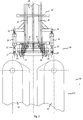
- Fig. 2 shows the general side view of a first embodiment of the present invention. Animals such as pigs are lead into the passageway or runway 10 and move or are urged up the slope towards the handling area 50.
- the runway 10 is bounded by outer walls or fences (only the near side fence 38 is shown).
- the handling area 50 includes a pair of parallel conveyors (only one is shown: 42) and a stunning unit 30 which may be advantageously the stunning device according to PCT/BE 92/00005.
- a runway barrier means 20 is provided between the end of the runway 10 and the start of the conveyor 42 .
- the runway barrier means 20 has an open state in which an animal may proceed from the runway 10 to the handling area 50 and a closed state in which access to the handling area is prevented.
- the closed state of the runway barrier means according to the first embodiment of the present invention is shown in a top view in Fig. 3.
- Two jaws 21,22 which make up a gate are provided on respective sides of the runway 10. In the closed position the cross-section of the runway 10 is reduced sufficiently that an animal can not proceed from the runway 10 to the pair of conveyors 41,42.
- the jaws 21,22 may be moved to touch in the centre of the runway 10 and completely block it.
- the jaws do not touch in the middle of the runway 10 but are spaced apart. With this latter arrangement the animal in the runway 10 still has eye contact with the handling area 50 and in particular with the rear of the animal in front. It has been found by experiment that the maintenance of eye contact with the animal in front has a calming influence on the animal remaining in the runway 10 possibly due to the general herding instinct of farm animals.
- the jaws 21,22 may be made of metal such as steel, stainless steel or aluminium, of rubber, wood, plastic or any other similar material. Further, the jaws 21,22 may be made of rods or mesh sufficiently close together the animals can not pass through. If the barrier means 20 is operated in unheated rooms it is preferred if metal jaws are heated to prevent a cold shock to the animal when it touches the jaws 21,22. Alternatively jaws 21,22 may be made of a material with a low thermal conductivity such as rubber which has a "warm" feel.
- the jaws 21,22 may rotate around the axes 23,24 and the surfaces 61,62 facing towards the runway 10 are convex.
- the convex surfaces 61,62 provide rounded surfaces against which an animal may push without hurting itself.
- the axes 23,24 lie far enough apart that the surfaces 61,62 in the closed condition lie generally at an angle to the centre line of the runway 10 with the inner edges of the jaws 21,22 being closer to the handling area 50 than the outer edges (as shown in Fig. 3).
- the cross-section of each jaw 21,22, as viewed from the top is a truncated sector of a circle with rounded edges as shown in Figs. 3 and 4.
- the open state of the runway barrier means 20 is shown in Fig. 4.
- the cylinder rods 31,32 of pneumatic cylinders 33,34 are rotationally attached to the "L" shaped joining pieces 25,27; 26,28 which themselves are attached to axles 23,24.
- the cylinder rods 31,32 extend and cause the jaws 21,22 to rotate about the axes 23,24 away from the centre of the runway 10.
- Pneumatic cylinders are preferred for the cylinders 33,34 as the compressibility of the air in the cylinders 33,34 provides a cushioning effect to the movement of the jaws 21,22.
- the invention is not however limited to pneumatic cylinders and hydraulic cylinders may be used. Further the invention is not limited to cylinders.
- the rods 31,32 may be driven forward by other mechanical means such as a rack and pinion.
- the pinion may be driven by an electric motor or any other suitable motor.
- the rods 31,32 may be dispensed with and the jaws 21,22 may be rotated by electric or other types of motors driving directly on the axles 23,24 or through gears or a series of gears.
- Fig. 4 also shows schematically a modification to the first embodiment of the present invention.
- One or more sensors 63,64 senses or sense when an animal enters the handling area 50 and sends a signal to the electronic control circuit 66 along the wires 71,72.
- the sensors 63,64 may be light sensitive devices receiving light from a lamp 60 placed at a distance such that an animal entering the handling area 50 interrupts the light beam.
- the sensors 63,64 may be optical sensors of the reflective type and be suitable for detecting the contrast in between the colour of the skin of the animal (e.g., light for pigs) and the background.
- the control circuit 66 sends a signal to the pneumatic control valve 67.
- Control valve 67 moves in accordance with the signal to supply air from the reservoir 65 to the cylinders 33,34 along pipes 68 and vents pipes 69 in order to retract rods 31,32 and close jaws 21,22. After a suitable delay the control circuit 66 sends a signal to the control valve 67 to stop supplying air and to close off pipes 68,69. The jaws 21,22 at this time are in their closed position and the animal can still move them slightly by compressing the air in the cylinders 33,34.
- the operation of the sensor 63,64, the circuit 66 and the control valve 67 is optimised so that only one animal at a time enters the handling area 50.
- a signal is automatically sent from the stunning unit 30 to the electronic control circuit 66 along the wires 70.
- the circuit 66 sends a signal to the pneumatic control valve 67 to allow air to pass through pipes 69 and to vent pipes 68 in order to extend cylinder rods 31,32.
- the jaws 21,22 are opened and the cycle mentioned above is repeated automatically. By these means only one animal at a time is allowed into the handling area 50 and the sequencing of the animals is controlled automatically.
- the cylinders 33,34 as shown in Figs. 3 and 4 are attached to frame elements 35,36 of the runway 10.
- the invention is not limited to this.
- the cylinders 33,34 may be attached to the conveyors 41,42 so that the delivery unit of the present invention may be delivered as a combined conveyor and delivery unit alternatively a combined conveyor, stunner and delivery unit.
- the present invention is not limited to an optical sensor 63,64 but any suitable optical e.g., infra-red, proximity, heat or mechanical sensor may be used. Further the invention is not limited to the control circuit details and components mentioned above. Any suitable control circuitry may be used which carries out the functions necessary to open and close the jaws 21,22 at the appropriate times.
- the invention is not limited to a stunner unit 30.
- the signal for indicating the end of the handling procedure can be generated by any other means. For instance the signal may be generated by an operator closing a switch when the handling is complete. Alternatively, if an animal is to be branded or weighed in the handling area 50, a signal from a further sensor may be generated automatically when the animal leaves the area 50.
- the stunning unit 30 only a single pair of conveyors 41,42, the barrier means 20 and the sensor 67 and its control circuitry were run continuously for several hours without human interference or control. A throughput of 350 pigs per hour was achieved and there was no single incident of incorrect stunning caused by pigs entering the stunning unit 30 too close together. Further, examination of the meat from the carcasses indicated uniform and consistently excellent quality of meat with excellent colour, pH and an absence of 'blood spots'. The pigs were observed to co-operate with the barrier means 20 without showing signs of distress or alarm. Nor were the pigs damaged by the operation of the barrier means 20.
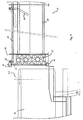
- Fig. 5 shows a side view of a second embodiment of the present invention in which the same reference numbers are used for the same items as in the first embodiment.
- Fig. 5 shows more clearly the axle 24 journalled in the bearing 43 and the jaw 22 attached to the axle 24.
- rod 32 is not attached to a cylinder but extends to a position close to the start of the runway 10. An operator standing at this position can close and open the jaw 22 by pushing or pulling on the rod 32.
- the jaw 21 is fixed so that the operator only has to manipulate the rod 32 to open and close one jaw 22 of the barrier means 20.
- the fixed jaw 21 is not fixed completely but is partly rotatable about the axes 23 and that the rotating jaw 22 may also rotate around axis 23, in both cases preferably against an elastic resistance such as a spring, so that the gripping action mentioned with respect to the first embodiment is maintained.
- both the rods 31, and 32 may be pushed back and forwards simultaneously by a single operator by linking them together by connecting levers and rods (not shown).
- a latch means 29 may be provided as shown in Fig. 5.
- the latch rod 29 rotates upwards out of the way.
- a device may be included on the runway side of the barrier means 20 e.g., between the latch means 29 and the barrier means 20, which urges the animal forward by means of a small electric shock or similar.
- the urging means can be triggered automatically by the opening of the jaws 21,22, e.g., by a limit switch feeding a signal to the control circuit 66, which in turn sends a signal to activate the urging means.
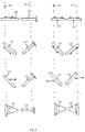
- Figs. 6 and 7 show various alternative arrangements for the barrier means 20 including jaws 21,22. All the arrangements are viewed from the top. The runway may be assumed to extend towards the bottom of the figure in each case.
- the jaws are shown in the closed position. The arrows indicate which of the jaws are movable and in which direction they move. All the jaws may be used with any of the embodiments of the invention.
- the cross-section of the jaws as viewed from the top is only shown schematically in the drawings. Suitable cross-sections may be chosen, which avoid frightening or damaging the animal e.g., by providing well-rounded, smooth contours towards the animal.
- the gap between the jaws in the closed position may be varied as required depending on the size, shape and strength of the animal.
- the jaws shown in Figs. 6 and 7 may be made from any of the materials and constructions described for the first and second embodiments.
- the jaws shown in Figs 6 and 7 may be used with any of the constructions of the apparatus according to the present invention described
- jaws 210 and 212 are gates which may be fixed to the wall 37 and extend from the wall 37 to the centre of the runway 10.
- Jaw 220 is located roughly perpendicular to wall 38 and is movable along its length to block or open the runway 10.
- Jaws 221 and 212 are angled with respect to the runway 10. Jaw 221 is movable along its length to open and close the runway 10. Alternatively, two jaws 221,213 may be provided which move along their lengths. Jaws 222 and 214 are located in a similar way to jaws 221,213 but move perpendicularly to the runway 10. The angle of the jaws 212,221,213,222,214 need not be 45° as shown, but may be any suitable angle.
- Jaws 224 and 215 are formed by inflatable bags.
- the bags may be inflated by air or other means.
- the animal is allowed through the barrier means 20 by deflating the air bag.
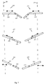
- Fig. 7 only arrangements are shown with both jaws movable.
- the invention is not limited thereto.
- One jaw may be fixed as described with reference to Fig. 6.
- the characteristic of all the arrangements of the jaws shown in Fig. 7 is that they have elastic gripping means.
- the jaws 21,22 are so designed that as the animal pushes against them with its head partially between them, the jaws move together and increase the pressure on the animal. This pressure is reversible, i.e. the grip by the jaws is elastic.
- this elastic grip was provided by the shape and length of the jaws and their rotation about the axes 23,24 as well as by the use of pneumatic cylinders which may provide a cushioning effect.
- Elastic gripping jaws need not only be achieved by shape and location of the jaws.
- jaws 220,221,222,211,213,214 of Fig. 6 may be provided with sensors which sense when the animal pushes against them. Activators can then move the jaws together slightly i.e., to close them a little, and exert more force on the animal. Thus the animal experiences the same elastic gripping effect as with the first and second embodiments.
- Jaws 216,226 of Fig. 7 comprise a first portion 310,320 and a second portion 311,321 which is rotationally mounted with respect to the first portion 310,320.
- the amount of rotation of the second portion 311,321 is preferably limited with respect to the first portion 310,320 by stops. It is preferable if the second portion 311,321 is elastically connected to the first portion so that as the animal pushes against the second portions 311,321, the resisting force to rotation of the second portion 311,321 increases.
- first and second portions 312,314,322,324:313,315,323,325 of jaws 217,227,218,228 is similar to that described for first and second portions 310,320;311,321 except the locations and movements of jaws 217,227,218,228 are different from those of 216,226.
- the cross-section of second portions 311,321,313,315,323,325 as viewed from the top may be a truncated sector of a circle with rounded edges as described for the first and second embodiments.
- a gap between the jaws when they are in the closed position should preferably be as wide or wider than the typical eye spacing of the animal to be delivered and sufficiently narrower than the typical shoulder width of the animal that it can not squeeze through.
- the jaws should be high enough to prevent the animal jumping over them or the runway 10 should be provided with a ceiling. The jaws should extend close enough to the floor 39 of the runway 10 that an animal cannot crawl or slither underneath them.
Landscapes
- Life Sciences & Earth Sciences (AREA)
- Engineering & Computer Science (AREA)
- Food Science & Technology (AREA)
- Housing For Livestock And Birds (AREA)
- Catching Or Destruction (AREA)
Claims (14)
- Einheit zur Zuführung von Tieren in einen Handhabungsbereich, die folgendes umfaßt:einen Treibgang (10) zum Zuführen von Tieren auf den Bearbeitungsbereich (50) zu, wobei der Treibgang Außenwände (37, 38) oder eine Umzäunung aufweist;eine Treibgangsperrvorrichtung (20);wobei die Treibgangsperrvorrichtung (20) mindestens eine erste und eine zweite Torvorrichtung (21, 22; 210 - 215, 220 - 224; 310 - 315, 320 - 325) aufweist;wobei sich in einer ersten Stellung die erste und die zweite Torvorrichtung (21, 22; 210 - 215, 220 - 224; 310 - 315, 320 - 325) jeweils von den Außenwänden oder der Umzäunung (37, 38) des Treibganges (10) bis zu ersten Stellen, die sich neben der Mitte des Treibganges (10) befinden, erstrecken, um zu verhindern, daß die Tiere den Treibgang (10) verlassen und in den Bearbeitungssbereich (50) eintreten; undwobei mindestens eine der ersten und zweiten Torvorrichtungen (21, 22; 210 - 215, 220 - 224; 310 - 315, 320 - 325) so ausgeführt ist, daß sie aus der entsprechenden ersten Stelle in eine zweite Stellung bewegbar ist, damit die Tiere in den Bearbeitungsbereich (50) eintreten können;
dadurch gekennzeichnet, daßdie mindestens eine der ersten und zweiten Torvorrichtungen (21, 22; 210 - 215, 220 - 224; 310 - 315, 320 - 325) mit der anderen der ersten und zweiten Torvorrichtungen (22, 21; 220 - 224; 210 - 215; 320 - 325; 310 - 315) zusammenwirkt, um eine elastische Greifeinrichtung zum elastischen Ergreifen des Kopfes des Tieres, wenn sich die erste und die zweite Torvorrichtung (21, 22; 210 - 215, 220 - 224; 310 - 315, 320 - 325) in der ersten Stellung neben der Mitte des Treibganges (10) befinden, zu bilden, so daß sich der Greifdruck erhöht und die mindestens eine der ersten und zweiten Torvorrichtungen (21, 22; 210 - 215, 220 - 224; 310 - 315, 320 - 325) sich weiter zur Mitte des Treibganges (10) bewegt, wenn sich das Tier vorwärtsbewegt. - Einheit nach Anspruch 1, weiterhin mit einer Steuervorrichtung (66) zum Steuern der Bewegung der mindestens einen der ersten und zweiten Torvorrichtungen (21, 22; 210 - 215, 220 - 224; 310 - 315, 320 - 325) zwischen die erste und zweite Stellung.
- Einheit nach Anspruch 1 oder 2, weiterhin mit einer Erfassungsvorrichtung (63, 64) zum Erfassen, ob ein Tier in den Bearbeitungsbereich (50) eingetreten ist, und zum Ausgeben eines ersten Signals.
- Einheit nach Anspruch 3, sofern er von Anspruch 2 abhängig ist, bei der die Steuervorrichtung (66) derart ausgebildet ist, daß sie das erste Signal von der Erfassungsvorrichtung (63, 64) empfängt und die mindestens eine der ersten und zweiten Torvorrichtungen (21, 22; 210 - 215, 220 - 224; 310 - 315, 320 - 325) antreibt, so daß sie sich aus der zweiten Stellung in die erste Stellung bewegt.
- Einheit nach einem der Ansprüche 1 bis 4, weiterhin mit einer Signalerzeugungsvorrichtung zum Ausgeben eines Signals, wenn die Verarbeitung eines Tieres im Bearbeitungsbereich (50) beendet ist.
- Einheit nach Anspruch 5, sofern er von einem der Ansprüche 2 bis 4 abhängig ist, bei der die Steuervorrichtung (66) derart ausgebildet ist, daß sie das zweite Signal von der Signalerzeugungsvorrichtung empfängt und die mindestens eine der ersten und zweiten Torvorrichtungen (21, 22; 210 - 215, 220 - 224; 310 - 315, 320 - 325) aus der ersten Stellung in die zweite Stellung bewegt.
- Einheit nach einem der Ansprüche 1 bis 6, weiterhin mit einer Treibvorrichtung zum Vorwärtstreiben eines Tieres auf den Bearbeitungsbereich (50) zu.
- Einheit nach Anspruch 7, sofern er von einem der Ansprüche 2 bis 6 abhängig ist, bei der die Steuervorrichtung (66) derart ausgebildet ist, daß sie die Treibvorrichtung antreibt, wenn die mindestens eine der ersten und zweiten Torvorrichtungen (21, 22; 210 - 215, 220 - 224; 310 - 315, 320 - 325) die zweite Stellung erreicht.
- Einheit nach einem der Ansprüche 1 bis 8, weiterhin mit mindestens einem Förderer (41, 42).
- Einheit nach einem der Ansprüche 1 bis 9, weiterhin mit einer Betäubungseinheit (30).
- Einheit nach einem der Ansprüche 1 bis 10, bei der die Lücke zwischen den ersten und zweiten Torvorrichtungen (21, 22; 210 - 215, 220 - 224; 310 - 315, 320 - 325), wenn sie sich in der geschlossenen oder ersten Stellung befinden, ebenso breit oder breiter als der Abstand zwischen den Augen des Tieres und enger als die Schultern des Tieres ist.
- Verfahren zum Zuführen von Tieren aus einem Treibgang (10) mit einer Umzäunung (37, 38) oder Außenwänden in einen Bearbeitungsbereich (50), das die folgenden Schritte umfaßt:Schritt 1: Einführen von Tieren in den Treibgang (10) und ermöglichen, daß sie sich auf den Bearbeitungsbereich (50) zu bewegen;Schritt 2: Durchlassen eines erstes Tieres aus dem Treibgang (10) in den Bearbeitungsbereich (50);Schritt 3: Bewegen mindestens einer ersten Torvorrichtung (21, 22; 210 - 215, 220 - 224; 310 - 315, 320 - 325) aus einer ersten Stellung neben der Umzäunung (37, 38) oder den Außenwänden in eine zweite Stellung neben der Mitte des Treibganges (10), um ein zweites Tier daran zu hindern, daß es in den Bearbeitungsbereich (50) eintritt, wobei in der zweiten Stellung neben der Mitte des Treibganges (10) die erste Torvorrichtung (21, 22; 210 - 215, 220 - 224; 310 - 315, 320 - 325) mit einer zweiten Torvorrichtung (21, 22; 210 - 215, 220 - 224; 310 - 315, 320 - 325) zum elastischen Ergreifen des Kopfes des Tieres zusammenwirkt, so daß sich der Greifdruck erhöht und die erste Torvorrichtung (21, 22; 210 - 215, 220 - 224; 310 - 315, 320 - 325) sich weiter zur Mitte des Treibganges (10) bewegt, wenn sich das Tier vorwärtsbewegt; undSchritt 4: Bewegen mindestens der ersten Torvorrichtung (21, 22; 210 - 215, 220 - 224; 310 - 315, 320 - 325) wieder in die erste Stellung nach der Behandlung des ersten Tieres und wiederholen der Schritte 2 bis 4.
- Verfahren nach Anspruch 12, weiterhin mit einem Schritt 5: Das zweite Tier antreiben, so daß es sich auf den Bearbeitungsbereich (50) zu bewegt, nach dem Bewegen mindestens der ersten Torvorrichtung (21, 22; 210 - 215, 220 - 224; 310 - 315, 320 - 325) in die erste Stellung in Schritt 4, und wiederholen der Schritte 2 bis 5.
- Verfahren nach Anspruch 12 oder 13, bei dem der Bewegungsschritt 3 weiterhin aufweist: das Bewegen mindestes der ersten Torvorrichtung (21, 22; 210 - 215, 220 - 224; 310 - 315, 320 - 325), so daß eine Lücke in der Mitte des Treibganges (10) gelassen wird, wobei die Lücke mindestens ebenso breit wie der Abstand zwischen den Augen des Tieres und enger als die Schultern des Tieres ist.
Priority Applications (8)
| Application Number | Priority Date | Filing Date | Title |
|---|---|---|---|
| DE69503754T DE69503754T2 (de) | 1995-05-05 | 1995-05-05 | Verfahren und Vorrichtung zur Beschickung von Tieren in eine Verarbeitungszone |
| EP95106862A EP0740903B1 (de) | 1995-05-05 | 1995-05-05 | Verfahren und Vorrichtung zur Beschickung von Tieren in eine Verarbeitungszone |
| ES95106862T ES2123178T3 (es) | 1995-05-05 | 1995-05-05 | Metodo para distribuir animales a una zona de tratamiento y un dispositivo para ello. |
| PCT/EP1996/001840 WO1996034531A1 (en) | 1995-05-05 | 1996-05-03 | Method of delivering animals to a processing area and an apparatus therefor |
| KR1019970706495A KR19980703085A (ko) | 1995-05-05 | 1996-05-03 | 처리구역으로 동물을 운반하는 방법 및 장치 |
| JP8533009A JPH11504807A (ja) | 1995-05-05 | 1996-05-03 | 動物を処理領域へ搬送する方法および装置 |
| PL96323191A PL323191A1 (en) | 1995-05-05 | 1996-05-03 | Method of bringing animals into a veterinary intervention zone and apparatus therefor |
| EP96919658A EP0822750B1 (de) | 1995-05-05 | 1996-05-03 | Verfahren und vorrichtung zur beschickung von tieren in eine verarbeitungszone |
Applications Claiming Priority (1)
| Application Number | Priority Date | Filing Date | Title |
|---|---|---|---|
| EP95106862A EP0740903B1 (de) | 1995-05-05 | 1995-05-05 | Verfahren und Vorrichtung zur Beschickung von Tieren in eine Verarbeitungszone |
Publications (2)
| Publication Number | Publication Date |
|---|---|
| EP0740903A1 EP0740903A1 (de) | 1996-11-06 |
| EP0740903B1 true EP0740903B1 (de) | 1998-07-29 |
Family
ID=8219231
Family Applications (2)
| Application Number | Title | Priority Date | Filing Date |
|---|---|---|---|
| EP95106862A Expired - Lifetime EP0740903B1 (de) | 1995-05-05 | 1995-05-05 | Verfahren und Vorrichtung zur Beschickung von Tieren in eine Verarbeitungszone |
| EP96919658A Expired - Lifetime EP0822750B1 (de) | 1995-05-05 | 1996-05-03 | Verfahren und vorrichtung zur beschickung von tieren in eine verarbeitungszone |
Family Applications After (1)
| Application Number | Title | Priority Date | Filing Date |
|---|---|---|---|
| EP96919658A Expired - Lifetime EP0822750B1 (de) | 1995-05-05 | 1996-05-03 | Verfahren und vorrichtung zur beschickung von tieren in eine verarbeitungszone |
Country Status (7)
| Country | Link |
|---|---|
| EP (2) | EP0740903B1 (de) |
| JP (1) | JPH11504807A (de) |
| KR (1) | KR19980703085A (de) |
| DE (1) | DE69503754T2 (de) |
| ES (1) | ES2123178T3 (de) |
| PL (1) | PL323191A1 (de) |
| WO (1) | WO1996034531A1 (de) |
Cited By (1)
| Publication number | Priority date | Publication date | Assignee | Title |
|---|---|---|---|---|
| DE10000794C2 (de) * | 1999-01-15 | 2002-10-02 | Schneider Hans | Nachtreibeeinrichtung |
Families Citing this family (1)
| Publication number | Priority date | Publication date | Assignee | Title |
|---|---|---|---|---|
| US7662396B2 (en) | 2001-03-26 | 2010-02-16 | The Trustees Of The University Of Pennsylvania | Compositions and methods for enhancing the immunogenicity of antigens |
Family Cites Families (11)
| Publication number | Priority date | Publication date | Assignee | Title |
|---|---|---|---|---|
| US3118174A (en) * | 1960-11-14 | 1964-01-21 | Alvin W Hughes | Method for animal immobilization preliminary to slaughtering |
| US3585983A (en) | 1968-03-05 | 1971-06-22 | Adrian Kantrowitz | Cardiac assisting pump |
| US4051840A (en) | 1976-01-05 | 1977-10-04 | Sinai Hospital Of Detroit | Dynamic aortic patch |
| US4630597A (en) | 1984-04-30 | 1986-12-23 | Adrian Kantrowitz | Dynamic aortic patch for thoracic or abdominal implantation |
| US4733652A (en) | 1985-12-31 | 1988-03-29 | Aisin Seiki Kabushiki Kaisha | Intra-aortic balloon |
| US4809681A (en) | 1986-03-28 | 1989-03-07 | Aisin Seiki Kabushiki Kaisha | Electrocardiographic measurement method for controlling an intra-aortic balloon pump |
| US4692148A (en) | 1986-03-28 | 1987-09-08 | Aisin Seiki Kabushiki Kaisha | Intra-aortic balloon pump apparatus and method of using same |
| US5169379A (en) | 1989-06-14 | 1992-12-08 | L-Vad Technology | In-series ventricular assist system and method of controlling same |
| ES2087523T3 (es) * | 1992-02-21 | 1996-07-16 | Hubert Vanhaecke | Aparato para aturdir animales. |
| DE4208387C2 (de) * | 1992-03-16 | 1996-08-08 | Banss Kg Maschf | Vorrichtung zum Versperren des Durchgangs für Schlachttiere |
| DE4226596C2 (de) * | 1992-08-11 | 1994-07-14 | Banss Kg Maschf | Vorrichtung und Verfahren zum Wiegen und Betäuben von Schlachttieren |
-
1995
- 1995-05-05 EP EP95106862A patent/EP0740903B1/de not_active Expired - Lifetime
- 1995-05-05 DE DE69503754T patent/DE69503754T2/de not_active Expired - Fee Related
- 1995-05-05 ES ES95106862T patent/ES2123178T3/es not_active Expired - Lifetime
-
1996
- 1996-05-03 JP JP8533009A patent/JPH11504807A/ja not_active Ceased
- 1996-05-03 KR KR1019970706495A patent/KR19980703085A/ko not_active Withdrawn
- 1996-05-03 EP EP96919658A patent/EP0822750B1/de not_active Expired - Lifetime
- 1996-05-03 WO PCT/EP1996/001840 patent/WO1996034531A1/en not_active Ceased
- 1996-05-03 PL PL96323191A patent/PL323191A1/xx unknown
Cited By (1)
| Publication number | Priority date | Publication date | Assignee | Title |
|---|---|---|---|---|
| DE10000794C2 (de) * | 1999-01-15 | 2002-10-02 | Schneider Hans | Nachtreibeeinrichtung |
Also Published As
| Publication number | Publication date |
|---|---|
| DE69503754D1 (de) | 1998-09-03 |
| WO1996034531A1 (en) | 1996-11-07 |
| EP0740903A1 (de) | 1996-11-06 |
| EP0822750B1 (de) | 1998-10-28 |
| KR19980703085A (ko) | 1998-09-05 |
| EP0822750A1 (de) | 1998-02-11 |
| DE69503754T2 (de) | 1999-04-29 |
| JPH11504807A (ja) | 1999-05-11 |
| ES2123178T3 (es) | 1999-01-01 |
| PL323191A1 (en) | 1998-03-16 |
Similar Documents
| Publication | Publication Date | Title |
|---|---|---|
| EP0225149B1 (de) | Betäuben von Tieren | |
| Grandin | Handling and welfare of livestock in slaughter plants. | |
| US20090145364A1 (en) | Livestock treatment carousel | |
| AU2007233561B2 (en) | Livestock handling device | |
| US4854268A (en) | Milking plant and sorting system | |
| US5852989A (en) | Method for conveying standing animals | |
| US5070818A (en) | Cattle conveyor | |
| CA3081730C (en) | Livestock handling apparatus | |
| EP0740903B1 (de) | Verfahren und Vorrichtung zur Beschickung von Tieren in eine Verarbeitungszone | |
| GB2324020A (en) | Animal sorting module | |
| WO2001058270A1 (en) | Animal handling apparatus | |
| WO2020174280A1 (en) | Device for restraining and moving an animal | |
| US4873749A (en) | Method and apparatus for supporting animal carcasses and pulling hides therefrom | |
| US3115670A (en) | Method for restraining animals | |
| US6209492B1 (en) | Method and apparatus for a mobile cart for herding livestock | |
| US20040147213A1 (en) | Method of and device for processing poultry to be slaughtered | |
| EP1460901B1 (de) | Vorrichtung und verfahren zum betäuben von schlachttieren | |
| Grandin | ‘Principles for the Design of Handling Facilities and Transport Systems | |
| KR200214149Y1 (ko) | 돼지 자동이송 저전압 전살장치 | |
| US12279592B2 (en) | Animal handling device | |
| AU596022B2 (en) | Animal feed and separating apparatus | |
| FR3150396A1 (fr) | Dispositif de recul sur cage de contention pour bovins | |
| US3848294A (en) | Handling live animals to prepare them for slaughter | |
| Grandin | Cattle Behavior and Cattle Handling | |
| NL8201607A (nl) | Inrichting voor het bedwelmen van slachtdieren. |
Legal Events
| Date | Code | Title | Description |
|---|---|---|---|
| PUAI | Public reference made under article 153(3) epc to a published international application that has entered the european phase |
Free format text: ORIGINAL CODE: 0009012 |
|
| AK | Designated contracting states |
Kind code of ref document: A1 Designated state(s): BE DE DK ES FR GB IT NL |
|
| RBV | Designated contracting states (corrected) |
Designated state(s): BE DE DK ES FR GB IT NL |
|
| 17P | Request for examination filed |
Effective date: 19970426 |
|
| 17Q | First examination report despatched |
Effective date: 19970625 |
|
| GRAG | Despatch of communication of intention to grant |
Free format text: ORIGINAL CODE: EPIDOS AGRA |
|
| GRAG | Despatch of communication of intention to grant |
Free format text: ORIGINAL CODE: EPIDOS AGRA |
|
| GRAH | Despatch of communication of intention to grant a patent |
Free format text: ORIGINAL CODE: EPIDOS IGRA |
|
| GRAH | Despatch of communication of intention to grant a patent |
Free format text: ORIGINAL CODE: EPIDOS IGRA |
|
| GRAA | (expected) grant |
Free format text: ORIGINAL CODE: 0009210 |
|
| AK | Designated contracting states |
Kind code of ref document: B1 Designated state(s): BE DE DK ES FR GB IT NL |
|
| PG25 | Lapsed in a contracting state [announced via postgrant information from national office to epo] |
Ref country code: IT Free format text: LAPSE BECAUSE OF FAILURE TO SUBMIT A TRANSLATION OF THE DESCRIPTION OR TO PAY THE FEE WITHIN THE PRESCRIBED TIME-LIMIT;WARNING: LAPSES OF ITALIAN PATENTS WITH EFFECTIVE DATE BEFORE 2007 MAY HAVE OCCURRED AT ANY TIME BEFORE 2007. THE CORRECT EFFECTIVE DATE MAY BE DIFFERENT FROM THE ONE RECORDED. Effective date: 19980729 |
|
| REF | Corresponds to: |
Ref document number: 69503754 Country of ref document: DE Date of ref document: 19980903 |
|
| PG25 | Lapsed in a contracting state [announced via postgrant information from national office to epo] |
Ref country code: DK Free format text: LAPSE BECAUSE OF FAILURE TO SUBMIT A TRANSLATION OF THE DESCRIPTION OR TO PAY THE FEE WITHIN THE PRESCRIBED TIME-LIMIT Effective date: 19981029 |
|
| ET | Fr: translation filed | ||
| REG | Reference to a national code |
Ref country code: ES Ref legal event code: FG2A Ref document number: 2123178 Country of ref document: ES Kind code of ref document: T3 |
|
| PG25 | Lapsed in a contracting state [announced via postgrant information from national office to epo] |
Ref country code: GB Free format text: LAPSE BECAUSE OF NON-PAYMENT OF DUE FEES Effective date: 19990505 |
|
| PLBE | No opposition filed within time limit |
Free format text: ORIGINAL CODE: 0009261 |
|
| STAA | Information on the status of an ep patent application or granted ep patent |
Free format text: STATUS: NO OPPOSITION FILED WITHIN TIME LIMIT |
|
| 26N | No opposition filed | ||
| GBPC | Gb: european patent ceased through non-payment of renewal fee |
Effective date: 19990505 |
|
| PGFP | Annual fee paid to national office [announced via postgrant information from national office to epo] |
Ref country code: NL Payment date: 20030404 Year of fee payment: 9 Ref country code: FR Payment date: 20030404 Year of fee payment: 9 Ref country code: DE Payment date: 20030404 Year of fee payment: 9 Ref country code: BE Payment date: 20030404 Year of fee payment: 9 |
|
| PGFP | Annual fee paid to national office [announced via postgrant information from national office to epo] |
Ref country code: ES Payment date: 20030415 Year of fee payment: 9 |
|
| PG25 | Lapsed in a contracting state [announced via postgrant information from national office to epo] |
Ref country code: ES Free format text: LAPSE BECAUSE OF NON-PAYMENT OF DUE FEES Effective date: 20040506 |
|
| PG25 | Lapsed in a contracting state [announced via postgrant information from national office to epo] |
Ref country code: BE Free format text: LAPSE BECAUSE OF NON-PAYMENT OF DUE FEES Effective date: 20040531 |
|
| BERE | Be: lapsed |
Owner name: G. *VAN WIJNSBERGHE EN CO. N.V. Effective date: 20040531 |
|
| PG25 | Lapsed in a contracting state [announced via postgrant information from national office to epo] |
Ref country code: NL Free format text: LAPSE BECAUSE OF NON-PAYMENT OF DUE FEES Effective date: 20041201 Ref country code: DE Free format text: LAPSE BECAUSE OF NON-PAYMENT OF DUE FEES Effective date: 20041201 |
|
| PG25 | Lapsed in a contracting state [announced via postgrant information from national office to epo] |
Ref country code: FR Free format text: LAPSE BECAUSE OF NON-PAYMENT OF DUE FEES Effective date: 20050131 |
|
| NLV4 | Nl: lapsed or anulled due to non-payment of the annual fee |
Effective date: 20041201 |
|
| REG | Reference to a national code |
Ref country code: FR Ref legal event code: ST |
|
| REG | Reference to a national code |
Ref country code: ES Ref legal event code: FD2A Effective date: 20040506 |