EP0740950A2 - Bassin de sédimentation, en particulier pour systèmes de circulation - Google Patents
Bassin de sédimentation, en particulier pour systèmes de circulation Download PDFInfo
- Publication number
- EP0740950A2 EP0740950A2 EP96890075A EP96890075A EP0740950A2 EP 0740950 A2 EP0740950 A2 EP 0740950A2 EP 96890075 A EP96890075 A EP 96890075A EP 96890075 A EP96890075 A EP 96890075A EP 0740950 A2 EP0740950 A2 EP 0740950A2
- Authority
- EP
- European Patent Office
- Prior art keywords
- basin
- guide device
- section
- liquid
- opening
- Prior art date
- Legal status (The legal status is an assumption and is not a legal conclusion. Google has not performed a legal analysis and makes no representation as to the accuracy of the status listed.)
- Withdrawn
Links
- 238000004062 sedimentation Methods 0.000 title claims abstract description 25
- 239000007788 liquid Substances 0.000 claims description 47
- 238000000605 extraction Methods 0.000 claims description 3
- 238000011109 contamination Methods 0.000 claims description 2
- 238000003780 insertion Methods 0.000 claims description 2
- 230000037431 insertion Effects 0.000 claims description 2
- 239000012530 fluid Substances 0.000 abstract 1
- 239000012535 impurity Substances 0.000 abstract 1
- 230000003134 recirculating effect Effects 0.000 abstract 1
- XLYOFNOQVPJJNP-UHFFFAOYSA-N water Substances O XLYOFNOQVPJJNP-UHFFFAOYSA-N 0.000 description 12
- 239000002245 particle Substances 0.000 description 10
- 239000010802 sludge Substances 0.000 description 6
- 239000000356 contaminant Substances 0.000 description 4
- 238000000926 separation method Methods 0.000 description 4
- 239000000654 additive Substances 0.000 description 3
- 238000004140 cleaning Methods 0.000 description 2
- 230000008021 deposition Effects 0.000 description 2
- 230000000694 effects Effects 0.000 description 2
- 239000000126 substance Substances 0.000 description 2
- 238000010276 construction Methods 0.000 description 1
- 238000001514 detection method Methods 0.000 description 1
- 238000010586 diagram Methods 0.000 description 1
- 238000007599 discharging Methods 0.000 description 1
- 239000012717 electrostatic precipitator Substances 0.000 description 1
- 238000002347 injection Methods 0.000 description 1
- 239000007924 injection Substances 0.000 description 1
- 238000009434 installation Methods 0.000 description 1
- 230000000737 periodic effect Effects 0.000 description 1
- 238000001556 precipitation Methods 0.000 description 1
- 238000000746 purification Methods 0.000 description 1
- 238000010791 quenching Methods 0.000 description 1
- 239000002002 slurry Substances 0.000 description 1
- 239000007787 solid Substances 0.000 description 1
- 239000000243 solution Substances 0.000 description 1
- 230000007704 transition Effects 0.000 description 1
- 239000012719 wet electrostatic precipitator Substances 0.000 description 1
Images

Classifications
-
- B—PERFORMING OPERATIONS; TRANSPORTING
- B01—PHYSICAL OR CHEMICAL PROCESSES OR APPARATUS IN GENERAL
- B01D—SEPARATION
- B01D21/00—Separation of suspended solid particles from liquids by sedimentation
- B01D21/02—Settling tanks with single outlets for the separated liquid
-
- B—PERFORMING OPERATIONS; TRANSPORTING
- B01—PHYSICAL OR CHEMICAL PROCESSES OR APPARATUS IN GENERAL
- B01D—SEPARATION
- B01D21/00—Separation of suspended solid particles from liquids by sedimentation
- B01D21/0039—Settling tanks provided with contact surfaces, e.g. baffles, particles
- B01D21/0042—Baffles or guide plates
-
- B—PERFORMING OPERATIONS; TRANSPORTING
- B01—PHYSICAL OR CHEMICAL PROCESSES OR APPARATUS IN GENERAL
- B01D—SEPARATION
- B01D21/00—Separation of suspended solid particles from liquids by sedimentation
- B01D21/24—Feed or discharge mechanisms for settling tanks
- B01D21/2405—Feed mechanisms for settling tanks
-
- B—PERFORMING OPERATIONS; TRANSPORTING
- B01—PHYSICAL OR CHEMICAL PROCESSES OR APPARATUS IN GENERAL
- B01D—SEPARATION
- B01D21/00—Separation of suspended solid particles from liquids by sedimentation
- B01D21/24—Feed or discharge mechanisms for settling tanks
- B01D21/2427—The feed or discharge opening located at a distant position from the side walls
-
- B—PERFORMING OPERATIONS; TRANSPORTING
- B01—PHYSICAL OR CHEMICAL PROCESSES OR APPARATUS IN GENERAL
- B01D—SEPARATION
- B01D21/00—Separation of suspended solid particles from liquids by sedimentation
- B01D21/24—Feed or discharge mechanisms for settling tanks
- B01D21/245—Discharge mechanisms for the sediments
Definitions
- the invention relates to a sedimentation basin, especially for circulatory systems according to the preamble of claim 1.
- Sedimentation basins are used in many areas of industry to separate contaminants from liquids.
- a water circuit for periodic cleaning of the precipitation surfaces is provided in wet electrostatic precipitators, the contaminants rinsed out of the filter having to be removed from the wash water before it is used further.
- this can take place by sedimentation in a tank provided for this purpose.
- the object of the present invention is to develop a sedimentation basin for water circulation systems which allows optimal separation of the particles contained in the liquid and, as a result, largely prevents their entrainment when the liquid is drawn out of the basin into the circuit while avoiding the disadvantages mentioned above.
- the sedimentation basin which is open at the top, can be placed directly in a cleaning system, where the liquid to be cleaned passes into the sedimentation basin via this opening. This eliminates any collection funnels and feed lines to the sedimentation basin.
- the sedimentation of particles is significantly improved by the even supply of the contaminated liquid from above through an opening that occupies the entire top surface of the basin. Between the guide device and the basin wall there is an area with clean liquid, which can be removed from there for return to the circuit without particles that are currently in the sedimentation phase being entrained when being drawn off.
- the above-mentioned effect is further improved by a funnel-shaped design of the guide device and a significantly better, almost complete separation of the contaminated, introduced liquid inside the guide device from the liquid cleaned by sedimentation outside the guide device is achieved.
- the guide device consists of an upper section which tapers conically downwards and, if need be, of an section thereon subsequent lower section with a substantially constant cross-section or smaller opening angle than that of the upper section, the opening angle of the upper section of the guide device being greater than that of the basin.
- the guiding device can consist of an essentially horizontal upper section and, if need be, an adjoining lower section with an essentially constant cross section or smaller opening angle than that of the upper section.
- At least one introduction opening in the upper section of the guide device is connected via a pipe section to the circulatory system located outside the basin, so that the contaminated liquid can be introduced into the basin without risk of contamination of the liquid already cleaned by the sedimentation.
- At least one introduction opening which defines the height of the liquid surface opens into the upper section of the guide device below the level of the overflow opening and the lowest discharge opening for the liquid lies above the lower end of the lower section of the guide device. This ensures that the liquid is continuously introduced below the liquid level in normal operation with the least possible disturbance of the sedimentation caused by the liquid introduction, for example due to liquid falling onto the liquid level.
- the axis of the or each discharge opening from the basin is oriented essentially tangentially to the wall of the basin, the plane of the discharge opening preferably being oriented substantially perpendicularly and radially to the vertical axis of the basin and the discharge opening opening in the same direction of rotation as the or each introduction.
- the particles that are possibly also transported along by the circular flow outside the guide device are thus carried past the discharge openings and are only carried along to a small extent by the liquid drawn off against the flow direction.
- the or each discharge line has a nozzle protruding into the basin with a discharge opening, thereby preventing liquid from being sucked in directly from the basin wall on which dropping particles.
- This nozzle is advantageously arranged at the greatest possible distance from the pool wall.
- a further improvement of the effect described above is possible if at least one liquid supply line is provided with a section oriented tangentially to the wall of the basin. With this construction, a flow tangential to the pool wall can be generated, which prevents the deposition of particles in the area of the pool wall and at the same time drives these particles away from the or each discharge opening.
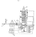
- the dust-laden exhaust gas is conveyed via a feed line 1 with an emergency chimney 2, at most after passing through at least one quench stage 3, with the aid of a fan 4 into a separation system 5.
- the separating plant 5 has the shape of a vertical tower, in which two electrostatic filter stages 6, 7 are arranged one above the other. Below the lower electrostatic filter 6 there is an equalization chamber 8, the upper limit of which is formed by a gas distributor plate 9. The lower limit of the equalization chamber 8 is formed by the liquid level 10 of the water in the sedimentation basin 11.
- lines 12 are provided with injection nozzles which are preferably directed towards the electrostatic filters 6, 7 or the gas distributor plate 9.
- the clean gas flow is conducted into the open via an opening forming the chimney 13.
- the electrostatic precipitators 6, 7 and the gas distributor plate 9 are cleaned, substances entering the wash water settle in the sedimentation basin 11 and are discharged from there by means of, for example, a screw 14 or a sludge pump and in a suitable device 15, e.g. a decanter, drained and disposed of as sludge.
- the water is advantageously returned to the pool 11.
- Any additives are stored in dry form in storage containers 16 and, before being introduced into the water of the water circuit in the basin 11 of the separating system 5, mixed with water to form a sludge in a stirred tank 17 and mixed in this form with the water in the basin 11.
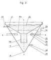
- FIG. 2 shows a longitudinal section of a preferred embodiment of the sedimentation basin 11 according to the invention on an enlarged scale.
- the basin 11 tapers conically downwards towards the bottom 18 in the form of an inverted truncated cone.
- Means 14 for discharging the settled sludge are provided on the bottom 18 or below it.
- a guide device 19 for the introduced liquid is mounted, which consists of two to one another subsequent sections 19a and 19b.
- the upper section 19a of the guide device 19 preferably tapers downward like the basin 11, but has a larger opening angle than the latter.
- the lower section 19b of the guide device 19 has a substantially constant cross section and ends above the bottom 18 of the basin 11.
- the lower section 19b of the guide device 19 ends essentially above this opening in the case of a discharge opening in the basin 11 for the sludge.
- a region is formed between the outside of the guide device 19 and the inside of the wall of the basin 11, which is also filled with liquid during normal operation of the system.
- an overflow line 24 opening at the level of the lower section 19b of the guide device 19 and its overflow opening 23, which determines the normal liquid level upwards, are used.
- the lowest liquid level during normal operation is defined by the lowest drain opening 27 for liquid from the basin 11 , which opens above the lower end of the guide device 19 or above its lower section 19b into the pool area between the guide device 19 and the pool wall.
- the discharge opening 27 is connected via line 25 to the liquid circuit of the separation system.
- the liquid from the circuit which is contaminated with the particles to be separated is brought either directly from above via an opening 20 which essentially occupies the entire top surface and / or via a line 22 through the basin 11 to the introduction opening 21 into the interior of the guide device.
- the insertion opening 21 is at a height above that of the overflow opening 23.
- the liquid level is at a height between the overflow opening 23 and the lowermost discharge opening 27.
- a circular flow in the basin 11 along its wall in the direction of the arrow S is generated by a ring line 28 with four inlets 29 oriented tangentially to the wall of the basin 11.
- the or each discharge opening 27 is provided at the front end of a connecting piece 26 projecting a little beyond the wall of the basin 11 and is oriented in the same sense as the liquid flow caused by the inlets 29, the entry of the liquid into the discharge openings 27 being essentially horizontal and tangential to the wall of the basin 11.
- the axis of the connecting piece 26 can be aligned radially to the axis A of the basin 11, as in FIG.
- a short curved end piece with the discharge opening 27 can be provided, so that the essentially tangential orientation of this opening is made possible.
- the spigot 26 can as in the embodiment of Fig. 3b also carried out essentially completely straight, but already provided tangentially to the axis A of the basin 11. The liquid flow in the direction of arrow S thus simultaneously prevents the deposition of sludge on the wall of the basin 11 and carries contaminants away from the discharge opening 27. This significantly reduces the risk of operational failures due to blockages or the like.
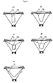
- FIGS. 4c and 4d show different design variants of the guide device 19 of the sedimentation basin.
- a substantially horizontal upper section 19a is followed by a lower section 19b with a substantially constant cross section up to the lower end.
- the lower section 19b tapers towards the bottom, but with a slightly smaller opening angle than that of the wall of the basin 11.
- FIGS. 4c and 4d are both characterized by a guide device 19 with a downwardly tapering upper section 19a.
- FIG. 4c this is followed by a lower section 19b with an essentially constant cross-section
- FIG. 4d an embodiment is shown with a likewise tapering lower section 19b.
- the upper section 19a of the guide device 19 in the basin 11 has a larger opening angle than the wall thereof, while the lower section 19b has a smaller opening angle than the basin 11 itself.
- the embodiment of FIG. 4e is finally equipped with a guide device 19 which tapers continuously from its upper end to its lower end and which has no transition between an upper and lower section.
- the opening angle of the funnel-shaped guide device 19 from FIG. 4e is larger than that of the wall of the basin 11.
Landscapes
- Chemical & Material Sciences (AREA)
- Chemical Kinetics & Catalysis (AREA)
- Sewage (AREA)
Applications Claiming Priority (2)
| Application Number | Priority Date | Filing Date | Title |
|---|---|---|---|
| AT0074895A AT402817B (de) | 1995-05-02 | 1995-05-02 | Sedimentationsbecken, speziell für kreislaufsysteme |
| AT748/95 | 1995-05-02 |
Publications (2)
| Publication Number | Publication Date |
|---|---|
| EP0740950A2 true EP0740950A2 (fr) | 1996-11-06 |
| EP0740950A3 EP0740950A3 (fr) | 1997-03-05 |
Family
ID=3498772
Family Applications (1)
| Application Number | Title | Priority Date | Filing Date |
|---|---|---|---|
| EP96890075A Withdrawn EP0740950A3 (fr) | 1995-05-02 | 1996-04-24 | Bassin de sédimentation, en particulier pour systèmes de circulation |
Country Status (2)
| Country | Link |
|---|---|
| EP (1) | EP0740950A3 (fr) |
| AT (1) | AT402817B (fr) |
Cited By (1)
| Publication number | Priority date | Publication date | Assignee | Title |
|---|---|---|---|---|
| CN105664544A (zh) * | 2016-03-29 | 2016-06-15 | 中国恩菲工程技术有限公司 | 浓密机 |
Citations (2)
| Publication number | Priority date | Publication date | Assignee | Title |
|---|---|---|---|---|
| US3617544A (en) * | 1970-05-11 | 1971-11-02 | Sybron Corp | Hot process settling tank having adjustable downcomer |
| EP0585103A2 (fr) * | 1992-08-24 | 1994-03-02 | Technology Finance Corporation (Proprietary) Limited | Procédé de traitement d'une suspension de particules solides dans un liquide porteur |
Family Cites Families (10)
| Publication number | Priority date | Publication date | Assignee | Title |
|---|---|---|---|---|
| DE281131C (fr) * | ||||
| US1919653A (en) * | 1931-11-27 | 1933-07-25 | Raymond A Hill | Hydraulic sand extractor |
| US4132643A (en) * | 1975-07-29 | 1979-01-02 | Hellqvist Ake O V | Sludge and slime separating and settling device |
| AT364325B (de) * | 1979-07-27 | 1981-10-12 | Mueller Hansjoerg Dr | Vorrichtung zur abtrennung von feststoffen aus fluessigkeiten |
| CS239007B1 (en) * | 1983-07-04 | 1985-12-16 | Vladimir Mackrle | Method of nitrogen substances containing biological activation sewage treatment and equipment for application of this method |
| DE3428557A1 (de) * | 1984-08-02 | 1986-02-13 | Linde Ag, 6200 Wiesbaden | Vorrichtung zur biologischen reinigung von abwasser |
| JPS643818A (en) * | 1987-06-25 | 1989-01-09 | Teac Corp | Optical recording and reproducing device |
| DE3812715A1 (de) * | 1988-04-16 | 1989-10-26 | Borsig Gmbh | Absetzbehaelter fuer eine belebtschlamm-abwasser-suspension |
| FI89703C (fi) * | 1989-03-06 | 1993-11-10 | Wiser Oy | Anordning foer behandling av vaetskor, speciellt avfallsvatten |
| DE29507254U1 (de) * | 1995-05-02 | 1995-06-29 | Alois Scheuch Ges.m.b.H., Ried im Innkreis | Sedimentationsbecken, speziell für Keislaufsysteme |
-
1995
- 1995-05-02 AT AT0074895A patent/AT402817B/de not_active IP Right Cessation
-
1996
- 1996-04-24 EP EP96890075A patent/EP0740950A3/fr not_active Withdrawn
Patent Citations (2)
| Publication number | Priority date | Publication date | Assignee | Title |
|---|---|---|---|---|
| US3617544A (en) * | 1970-05-11 | 1971-11-02 | Sybron Corp | Hot process settling tank having adjustable downcomer |
| EP0585103A2 (fr) * | 1992-08-24 | 1994-03-02 | Technology Finance Corporation (Proprietary) Limited | Procédé de traitement d'une suspension de particules solides dans un liquide porteur |
Cited By (1)
| Publication number | Priority date | Publication date | Assignee | Title |
|---|---|---|---|---|
| CN105664544A (zh) * | 2016-03-29 | 2016-06-15 | 中国恩菲工程技术有限公司 | 浓密机 |
Also Published As
| Publication number | Publication date |
|---|---|
| AT402817B (de) | 1997-09-25 |
| ATA74895A (de) | 1997-01-15 |
| EP0740950A3 (fr) | 1997-03-05 |
Similar Documents
| Publication | Publication Date | Title |
|---|---|---|
| DE68913120T2 (de) | Separator. | |
| EP0195826A1 (fr) | Mélangeur, dispositif de sédimentation etc. pour liquides contenant des particules | |
| DE2524544A1 (de) | Vorrichtung und verfahren zur behandlung von gasen oder fluessigkeiten, die durch feste teilchen verunreinigt sind | |
| DE1457299C3 (de) | Vorrichtung zum Entfernen von Teilchen aus einem verunreinigten gasförmigen Medium | |
| EP3222357A1 (fr) | Separateur de boue | |
| DE19953961B4 (de) | Vorrichtung zum Abscheiden von Sinkstoffen aus Abwasser | |
| DE4331415C2 (de) | Vorrichtung zur Behandlung eines Gasstromes mit Waschflüssigkeit | |
| DE2850690A1 (de) | Verfahren und vorrichtungen zur zentrifugalen behandlung von fluiden oder gasen zur abscheidung von verunreinigungen mittels hoher geschwindigkeit | |
| DE2512104C2 (de) | Zyklon zum Abscheiden von Feststoffen aus Flüssigkeiten oder Gasen | |
| DE60012329T2 (de) | Verbesserte einspritzung von mit feststoffpartikeln beladenem wasser in einen zentrifugalabscheider | |
| EP1137469B1 (fr) | Dispositif de separation d'eau usee | |
| DE2708135A1 (de) | Vorrichtung zur aufbereitung von truebe | |
| DE10200599B4 (de) | Vorrichtung zum Abscheiden von organischem und anorganischem Material aus einer Flüssigkeit | |
| DE19850320C2 (de) | Kompaktanlage für die mechanische Reinigung von Abwasser | |
| EP2893981B1 (fr) | Séparateur de boue | |
| EP0740950A2 (fr) | Bassin de sédimentation, en particulier pour systèmes de circulation | |
| DE20018715U1 (de) | Sandfanganlage | |
| DE102006020273B4 (de) | Vorrichtung und Verfahren zum Reinigen von Abwasser | |
| DE19521741C2 (de) | Durchlaufabscheider mit zwei Stufen zum Abtrennen von Feststoffteilchen aus einer strömenden Flüssigkeit | |
| EP0965375B1 (fr) | Dispositif pour la séparation de solide d'un mélange solide-liquide | |
| DE29507254U1 (de) | Sedimentationsbecken, speziell für Keislaufsysteme | |
| AT780U1 (de) | Sedimentationsbecken, speziell für kreislaufsysteme | |
| DE20010899U1 (de) | Hydrozyklon | |
| EP0508047A1 (fr) | Clarificateur pour l'épuration des eaux usées | |
| DE102017128560B3 (de) | Vorrichtung zum Abscheiden von Sinkstoffen aus Flüssigkeiten, Reinigungseinrichtung und Verfahren zum Abscheiden von Sinkstoffen |
Legal Events
| Date | Code | Title | Description |
|---|---|---|---|
| PUAI | Public reference made under article 153(3) epc to a published international application that has entered the european phase |
Free format text: ORIGINAL CODE: 0009012 |
|
| AK | Designated contracting states |
Kind code of ref document: A2 Designated state(s): AT BE DE ES FR GB IT |
|
| PUAL | Search report despatched |
Free format text: ORIGINAL CODE: 0009013 |
|
| AK | Designated contracting states |
Kind code of ref document: A3 Designated state(s): AT BE DE ES FR GB IT |
|
| 17P | Request for examination filed |
Effective date: 19970402 |
|
| RAP1 | Party data changed (applicant data changed or rights of an application transferred) |
Owner name: SCHEUCH GMBH |
|
| 17Q | First examination report despatched |
Effective date: 20010418 |
|
| STAA | Information on the status of an ep patent application or granted ep patent |
Free format text: STATUS: THE APPLICATION IS DEEMED TO BE WITHDRAWN |
|
| 18D | Application deemed to be withdrawn |
Effective date: 20010829 |