EP0740963A2 - Installation pour la purification des gaz d'échappement chargés de poussières - Google Patents
Installation pour la purification des gaz d'échappement chargés de poussières Download PDFInfo
- Publication number
- EP0740963A2 EP0740963A2 EP96890076A EP96890076A EP0740963A2 EP 0740963 A2 EP0740963 A2 EP 0740963A2 EP 96890076 A EP96890076 A EP 96890076A EP 96890076 A EP96890076 A EP 96890076A EP 0740963 A2 EP0740963 A2 EP 0740963A2
- Authority
- EP
- European Patent Office
- Prior art keywords
- water
- filter
- exhaust gas
- cleaning
- electrostatic
- Prior art date
- Legal status (The legal status is an assumption and is not a legal conclusion. Google has not performed a legal analysis and makes no representation as to the accuracy of the status listed.)
- Granted
Links
Images


Classifications
-
- B—PERFORMING OPERATIONS; TRANSPORTING
- B03—SEPARATION OF SOLID MATERIALS USING LIQUIDS OR USING PNEUMATIC TABLES OR JIGS; MAGNETIC OR ELECTROSTATIC SEPARATION OF SOLID MATERIALS FROM SOLID MATERIALS OR FLUIDS; SEPARATION BY HIGH-VOLTAGE ELECTRIC FIELDS
- B03C—MAGNETIC OR ELECTROSTATIC SEPARATION OF SOLID MATERIALS FROM SOLID MATERIALS OR FLUIDS; SEPARATION BY HIGH-VOLTAGE ELECTRIC FIELDS
- B03C3/00—Separating dispersed particles from gases or vapour, e.g. air, by electrostatic effect
- B03C3/02—Plant or installations having external electricity supply
- B03C3/025—Combinations of electrostatic separators, e.g. in parallel or in series, stacked separators or dry-wet separator combinations
-
- B—PERFORMING OPERATIONS; TRANSPORTING
- B01—PHYSICAL OR CHEMICAL PROCESSES OR APPARATUS IN GENERAL
- B01D—SEPARATION
- B01D53/00—Separation of gases or vapours; Recovering vapours of volatile solvents from gases; Chemical or biological purification of waste gases, e.g. engine exhaust gases, smoke, fumes, flue gases, aerosols
- B01D53/34—Chemical or biological purification of waste gases
- B01D53/74—General processes for purification of waste gases; Apparatus or devices specially adapted therefor
- B01D53/75—Multi-step processes
-
- B—PERFORMING OPERATIONS; TRANSPORTING
- B01—PHYSICAL OR CHEMICAL PROCESSES OR APPARATUS IN GENERAL
- B01D—SEPARATION
- B01D53/00—Separation of gases or vapours; Recovering vapours of volatile solvents from gases; Chemical or biological purification of waste gases, e.g. engine exhaust gases, smoke, fumes, flue gases, aerosols
- B01D53/34—Chemical or biological purification of waste gases
- B01D53/74—General processes for purification of waste gases; Apparatus or devices specially adapted therefor
- B01D53/77—Liquid phase processes
- B01D53/78—Liquid phase processes with gas-liquid contact
-
- B—PERFORMING OPERATIONS; TRANSPORTING
- B03—SEPARATION OF SOLID MATERIALS USING LIQUIDS OR USING PNEUMATIC TABLES OR JIGS; MAGNETIC OR ELECTROSTATIC SEPARATION OF SOLID MATERIALS FROM SOLID MATERIALS OR FLUIDS; SEPARATION BY HIGH-VOLTAGE ELECTRIC FIELDS
- B03C—MAGNETIC OR ELECTROSTATIC SEPARATION OF SOLID MATERIALS FROM SOLID MATERIALS OR FLUIDS; SEPARATION BY HIGH-VOLTAGE ELECTRIC FIELDS
- B03C3/00—Separating dispersed particles from gases or vapour, e.g. air, by electrostatic effect
- B03C3/02—Plant or installations having external electricity supply
- B03C3/16—Plant or installations having external electricity supply wet type
-
- B—PERFORMING OPERATIONS; TRANSPORTING
- B03—SEPARATION OF SOLID MATERIALS USING LIQUIDS OR USING PNEUMATIC TABLES OR JIGS; MAGNETIC OR ELECTROSTATIC SEPARATION OF SOLID MATERIALS FROM SOLID MATERIALS OR FLUIDS; SEPARATION BY HIGH-VOLTAGE ELECTRIC FIELDS
- B03C—MAGNETIC OR ELECTROSTATIC SEPARATION OF SOLID MATERIALS FROM SOLID MATERIALS OR FLUIDS; SEPARATION BY HIGH-VOLTAGE ELECTRIC FIELDS
- B03C3/00—Separating dispersed particles from gases or vapour, e.g. air, by electrostatic effect
- B03C3/34—Constructional details or accessories or operation thereof
- B03C3/66—Applications of electricity supply techniques
- B03C3/70—Applications of electricity supply techniques insulating in electric separators
-
- B—PERFORMING OPERATIONS; TRANSPORTING
- B03—SEPARATION OF SOLID MATERIALS USING LIQUIDS OR USING PNEUMATIC TABLES OR JIGS; MAGNETIC OR ELECTROSTATIC SEPARATION OF SOLID MATERIALS FROM SOLID MATERIALS OR FLUIDS; SEPARATION BY HIGH-VOLTAGE ELECTRIC FIELDS
- B03C—MAGNETIC OR ELECTROSTATIC SEPARATION OF SOLID MATERIALS FROM SOLID MATERIALS OR FLUIDS; SEPARATION BY HIGH-VOLTAGE ELECTRIC FIELDS
- B03C3/00—Separating dispersed particles from gases or vapour, e.g. air, by electrostatic effect
- B03C3/34—Constructional details or accessories or operation thereof
- B03C3/74—Cleaning the electrodes
- B03C3/78—Cleaning the electrodes by washing
-
- B—PERFORMING OPERATIONS; TRANSPORTING
- B03—SEPARATION OF SOLID MATERIALS USING LIQUIDS OR USING PNEUMATIC TABLES OR JIGS; MAGNETIC OR ELECTROSTATIC SEPARATION OF SOLID MATERIALS FROM SOLID MATERIALS OR FLUIDS; SEPARATION BY HIGH-VOLTAGE ELECTRIC FIELDS
- B03C—MAGNETIC OR ELECTROSTATIC SEPARATION OF SOLID MATERIALS FROM SOLID MATERIALS OR FLUIDS; SEPARATION BY HIGH-VOLTAGE ELECTRIC FIELDS
- B03C3/00—Separating dispersed particles from gases or vapour, e.g. air, by electrostatic effect
- B03C3/34—Constructional details or accessories or operation thereof
- B03C3/86—Electrode-carrying means
-
- B—PERFORMING OPERATIONS; TRANSPORTING
- B03—SEPARATION OF SOLID MATERIALS USING LIQUIDS OR USING PNEUMATIC TABLES OR JIGS; MAGNETIC OR ELECTROSTATIC SEPARATION OF SOLID MATERIALS FROM SOLID MATERIALS OR FLUIDS; SEPARATION BY HIGH-VOLTAGE ELECTRIC FIELDS
- B03C—MAGNETIC OR ELECTROSTATIC SEPARATION OF SOLID MATERIALS FROM SOLID MATERIALS OR FLUIDS; SEPARATION BY HIGH-VOLTAGE ELECTRIC FIELDS
- B03C3/00—Separating dispersed particles from gases or vapour, e.g. air, by electrostatic effect
- B03C3/34—Constructional details or accessories or operation thereof
- B03C3/88—Cleaning-out collected particles
Definitions
- the invention relates to a system for cleaning dust-containing exhaust gas, in particular exhaust gas and / or exhaust air from a drying system, especially for wood or wood chips according to the preamble of claim 1.
- Dust-containing exhaust gases or exhaust air occur in many areas of industry, e.g. in drying plants of the wood industry.
- dust, resin aerosols and water vapor but also depending on the material to be dried, steam-volatile, gaseous organic substances, possibly also inorganic revenge gas components and fly ash, are discharged.
- dry-working exhaust air purification systems such as cyclones, fabric or layer bed filters and dry electrostatic filters or electric layer bed filters are known.
- the separation efficiency of cyclones is only sufficient for massive particles; they are not suitable for fine dust and organic contaminants.
- Stratified bed filters without charging the filter bed also show insufficient separation rates.
- Electric stratified bed filters can reduce dust-like emissions well, but due to the necessary circulation and the cleaning of the particles in the filter bed, they are very extensive and expensive.
- organic filters can hardly be reduced with these filters.
- Dry electrostatic precipitators pose a great fire risk due to arcing due to organic deposits.
- Fabric filters do show good separation performance with dust-like emissions, but they can cause sticky impurities in the exhaust gas, such as e.g. in the form of sticky resin aerosols in the wood industry, quickly become unusable.
- EP-A-0 358 006 describes a method and a system for cleaning exhaust gas originating from drying systems.
- the system consists of a dry separator, for example a cyclone or electrostatic precipitator, a downstream washing and condensation device for the exhaust gas with a sump designed as a coarse separator and a wet-deep bed filter and a flotation device.
- the gas is fed to another electrostatic filter and cleaned again. Since the system must be switched off during cleaning, large amounts of raw gas can be used during this time escape uncleaned and after switching on again large quantities of the substances cleaned in the filter are released into the atmosphere with the re-starting gas flow.
- the object of the present invention is to develop a system for cleaning exhaust gases of the type described at the outset for continuous operation and the greatest possible separation efficiency while avoiding the risk of sparking due to organic deposits and the further disadvantages mentioned above.
- the multi-stage arrangement enables high separation rates to be achieved.
- the risk of fire due to organic deposits is reduced to a minimum by cleaning the electrostatic filter by means of the injection devices.
- the cleaning can be carried out for each filter stage independently, periodically or according to the degree of contamination. Due to the multi-stage arrangement, each filter stage can remain fully operational in the raw gas stream during the cleaning of one filter stage, so that continuous operation of the system is guaranteed even during the short cleaning times and only short-term clean gas dust values of maximum 25 mg / m 3 can occur. Due to the separation effect of the filter stage (s) that remain in operation, excessive emissions after cleaning a filter stage can be largely prevented.
- the vertical arrangement of the filter stages means that a smaller footprint of the system is required and various intermediate structural stages, such as a separate chimney, can be omitted.
- the Water dividers between the filter stages allow the exhaust gases to pass through and collect the liquid coming from above.
- These devices according to the invention are necessary for an independent function of the filter stages arranged one above the other.
- the system according to the invention allows simple and rapid conversion or upgrading also for the separation of especially short-chain organic contaminants by installing additional separating devices, such as packed scrubbers, in the filter stage following the water separating floor, the independent operation of the previous filter stage (s) and their independent cleaning is not affected.
- the water is circulated, preferably via a cleaning system. This can drastically reduce the system's water requirements.
- the advantageous embodiment always ensures an equally efficient cleaning of the electrostatic filter.
- At least one of the filter stages is designed as an air-cooled tubular filter with preferably round tubes. Due to the simple design of the air cooling, condensation forms on the parts of the electrostatic precipitator, which flushes away a large part of the dust and organic substances during normal operation of the system. Also, the above-mentioned impurities cannot properly adhere to the moist components, so that cleaning by the water injection can have a significantly better effect.
- devices for withdrawing the heated cooling air flow after flowing through the tube filter and lines for supplying this heated cooling air flow into the exhaust gas flow downstream of the last filter stage are provided, whereby on the one hand the clean gas flow heated in this way does not form an optically conspicuous vapor cloud after leaving the system and, moreover, any residual emissions still in the clean gas are not reflected at the plant outlet or in the vicinity.
- Separation plants necessary in conventional plants can therefore be omitted in the plant according to the invention with the above feature.
- the water is led from the water separating floor into a water circuit separate from the or any other water circuit, so that the organic ones Contaminated water can be cleaned in a suitable manner and the organic substances can be disposed of.
- an insulated suspension of the electrodes of the or each electrostatic filter inside the system is of great importance for the safe operation of the system. Otherwise there may be a loss of voltage, short circuits, arcing, etc.
- Sticky substances e.g. Resin aerosols can form moist, sticky and conductive layers on the electrode suspensions. So far, expensive, complex and damage-prone ceramic insulators have been used.
- the insulated suspensions for the electrodes of the filter stages are arranged outside the actual exhaust gas flow in housings which are open at the bottom and at least one purge air line opens into the housing. This creates a purge air flow that is counter to the inflow of contaminated raw gas, and the pollution of the electrode suspension can be significantly reduced and its structure simplified or the service life or the time between necessary cleaning of the suspension can be extended.
- At least one purge air line opens into the upper region of the housing and at the lower, open end of the housing there is an end piece of a purge air line surrounding the suspension of the electrode with at least one obliquely downward and inward outlet opening.
- a simple design for economical promotion and preferably also to achieve the heating of the purge air for the suspension housing can be achieved in that devices for separating part of the cooling air of the electrostatic precipitators, preferably in the flow direction behind the electrostatic precipitator, are provided and at least one of the purge air lines is connected to these devices. This means that a large area of the air lines can be merged or line sections can be shared. After flowing through the filter stage, the air is also warmed without additional energy, which prevents condensation in the housing of the suspension and prevents short circuits.
- devices for adding or metering additives into the water of the or each are Water cycle provided.
- wood sanding dust can be added directly to the rinse water as an additive that increases the transportability of tar or similar sticky substances and can thus be transported directly to its destination without losses.
- Ca (OH) 2 , flocculants or the like which are mainly used to adjust the pH, are also added directly to the water, as a result of which the effect can be metered better and smaller amounts are necessary.
- the introduction of dry additives into the water after mixing with water in a sludge-like state for which the devices advantageously comprise an agitator with a water connection and at least one connecting line from the agitator to a point in the water circuit in the flow direction upstream of the first electrostatic filter and after a possible one Water purification system is provided.
- the fan in the feed line for the raw gas is provided with a water injection nozzle directed towards its impeller.
- At least a portion of the gas distribution plate is provided with poppet valves for optional closing or opening.
- the entire surface of the gas distribution plate is preferably provided with arrangements of poppet valves which are subdivided into separately operable subunits.
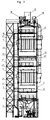
- the dust-laden exhaust gas is conveyed via a feed line 1 with an emergency chimney 2, at most after passing through at least one quench stage 3, with the aid of a fan 4 into the separation system 5.
- a water nozzle for periodic or continuous water injection is provided in the fan 4 for periodic or continuous water injection, by means of which water that is deposited can be used to wash away any deposited dirt on the impeller and inside the fan 4.
- the separator 5 has the shape of a vertical tower, in which two electrostatic filters 6, 7 are arranged one above the other. Below the lower electrostatic filter 6 there is an equalization chamber 8 for the raw gas flow, the upper limit of which is formed by a gas distributor plate 9, advantageously with adjustable middle positions (see FIG. 5).
- the lower limit of the equalization chamber 8 is formed by the liquid level 10 of the water in the collecting and separating basin 11.
- lines 12 are provided with injection nozzles which are preferably directed towards the electrostatic filters 6, 7 or the gas distributor plate 9.
- the lowermost lines 12 directed towards the gas distributor plate 9 are preferably operated continuously and form a first scrubber level.
- the clean gas flow is passed outside through an opening forming the chimney 13.
- the substances entering the wash water during the cleaning of the electrostatic filters 6, 7 and the gas distributor plate 9 settle on the bottom of the collecting and separating basin 11 and can be removed, for example, with the aid of a screw 14 or a sludge pump and in a suitable device 15, for example one Decanters, drained and disposed of as sludge.
- the water is returned to the pool 11.
- Any additives such as Ca (OH) 2 for setting the desired pH, flocculant or wood sanding dust to facilitate transportation for tar and the like are stored in dry form in storage containers 16 and before being introduced into the water of the water circuit of the separating system 5 in a stirred container 17 mixed with water to form a sludge and supplied to the water in the pool 11 in this form.
- Chemicals for the chemical binding of substances in the raw gas, especially for the separation of organic substances in a wet process can also be introduced into the water to be sprayed in this way.
- FIG. 2 and 3 show two different longitudinal sections of the separating system 5.
- the housings 18 for the suspensions of the electrodes 19 of the two electrostatic filters 6, 7 can be clearly seen, which are shown in detail in FIG. 6.
- the water separating floor 20 between the electrostatic filter stages 6, 7 prevents water resulting from the cleaning of the upper electrostatic filter 7 from dripping onto the electrostatic filter 6 below. This ensures a structural separation and thus an independent function of the two filter stages 6, 7.
- the water circuits for cleaning the lower electrostatic filter 6 and the upper electrostatic filter 7 can be separated.
- one of the filters 6, 7, advantageously the upper, second filter 7 and its water circuit is designed for the separation of specially short-chain organic substances such as formaldehyde, while at the same time the lower, first filter 6 with a separate water circuit for separation mainly dust-like contaminants and long-chain organic molecules.
- a conventional packed scrubber which can be installed in the system according to the invention without complex conversion work, can at most additionally be provided above the water separating floor 20 between the filter stages 6, 7.
- the water separating floor 20 permits the passage of gaseous fluids, but catches liquids coming from above, which are led through a number of channels or funnels arranged one above the other and offset from one another with drains into the channel underneath and finally out of the channel deducted from the lowest level and in the example shown are fed to the collecting and settling basin 11 into which the water from the cleaning of the lower filter 6 drips directly.
- the water drawn off from the water separating floor 20 could also be conducted into a separate circuit, ie via a cleaning system separated from the basin 11 and from there back again for cleaning the upper filter 7 or for injection for wet cleaning of the exhaust gas via the lines 12.
- the filters 6, 7, in particular the precipitation areas for the separated particles or substances can be periodically cleaned.
- intervals between the cleaning of the first, more polluted filter stage 6 of approximately three hours and intervals between the cleaning of the second, less contaminated raw gas filter stage 7 of approximately usual twelve hours are suitable compromise between continuous operation of the system as far as possible and prevention of operational disturbance or performance-reducing pollution.
- Fig. 4 shows an advantageous embodiment of the electrostatic filters 6, 7 as a tube filter.
- a space 24 which is delimited from the raw gas area of the separating plant 5 by means of an upper plate 22 and a lower plate 23, is present in the form of preferably circular tubes 21 through which the raw gas flows.
- the ionization wires 25 tensioned in the electrode frame 19 run through the individual tubes 21, preferably coaxially. Outside air is drawn in through the inlet openings 26 and between the tubes 21 through the space 24, as a result of which the walls of the tubes 21 are cooled.
- the heated air is drawn off via a line 27 with the aid of at least one fan and is preferably introduced into the chimney 13 behind the upper electrostatic filter 7 and thus mixed with the clean gas emerging from the system 5 in order to increase the temperature.
- a particularly good match between the two filter stages was achieved with a voltage for the first filter stage 6 of approximately 80 kV and for the second stage 7 of approximately 70 kV and a current of approximately 310 mA for the first stage 6 and approximately 410 mA achieved for the second electrostatic filter 7, these values, of course, while maintaining the lower Voltage and higher current in the second filter stage 7, depending on the geometric conditions in the respective electrostatic filters can be changed.
- FIG. 5 shows the gas distributor plate 9 with its preferably circular through openings 28 for the raw gas.
- This device serves to equalize the gas flow introduced mostly at an angle to the longitudinal axis of the system 5, usually even at a right angle, in such a way that the flow velocity is essentially the same over the entire cross section of the system 5.
- This influencing of the gas flow can be further improved if different areas of the surface of the gas distribution plate 9 can be specifically shut off or released for the flow.
- separate and separately operable valve arrangements are advantageously provided in different surface areas of the gas distribution plate 9.
- These are preferably designed as poppet valve arrangements which consist of essentially flat plate plates 38 which can cover the openings in the gas distribution plate 9 and which are mounted on support frames 37.
- the support frame 37 can itself be movably mounted or the plate plates 38 can be movably actuated on the frame 37.
- the suspension of the electrode frame 19 is shown enlarged.
- the electrode frame 19 hangs on a straight rod or a tube 29 without any further geometric configuration, as is the case with conventional ceramic insulators.
- the upper end of the rod 29 is supported by a projection or by a washer 30 connected to the upper end of the rod 29 on a normal plastic bushing 31, which in turn rests on a substantially horizontal wall section 32 of the wall of the system 5.
- the deposition of sticky, moist and conductive precipitate on the rod or tube 29 is prevented by generating a purge air flow directed downwards and out of the housing 18, which largely prevents the ingress of contaminated raw gas.
- a first purge air line 33 is provided in the upper region of the housing 18, which causes a flow of pure purge air directed downward along the rod 29.
- This purge air is advantageously branched off from the cooling air of the electrostatic filters 6, 7 after they have flowed through them and thus have been heated.
- the purge air is advantageously already heated and there is no condensation and accumulation of any dirt particles that may have penetrated in the housing 18.
- a second purge air line 34 is provided towards the lower end of the housing 18, which ends in an end piece 35 that surrounds the rod or the pipe 29 in a ring-shaped manner.
- This end piece 35 is provided with openings, nozzles, slots or the like 36 distributed along its circumference, if necessary also with a completely circumferential slot, which (is) directed obliquely inwards towards the rod 29 and downwards. This creates a kind of air curtain and an additional flow against the inflow direction into the housing 18 and opposite to the raw gas flow.
Landscapes
- Engineering & Computer Science (AREA)
- Chemical & Material Sciences (AREA)
- Environmental & Geological Engineering (AREA)
- Chemical Kinetics & Catalysis (AREA)
- Analytical Chemistry (AREA)
- General Chemical & Material Sciences (AREA)
- Oil, Petroleum & Natural Gas (AREA)
- Health & Medical Sciences (AREA)
- Biomedical Technology (AREA)
- Electrostatic Separation (AREA)
- Filtering Of Dispersed Particles In Gases (AREA)
- Processes For Solid Components From Exhaust (AREA)
- Electrical Discharge Machining, Electrochemical Machining, And Combined Machining (AREA)
- Separating Particles In Gases By Inertia (AREA)
- Solid-Sorbent Or Filter-Aiding Compositions (AREA)
- Treating Waste Gases (AREA)
- Separation Of Particles Using Liquids (AREA)
Applications Claiming Priority (3)
| Application Number | Priority Date | Filing Date | Title |
|---|---|---|---|
| AT74995 | 1995-05-02 | ||
| AT749/95 | 1995-05-02 | ||
| AT0074995A AT406024B (de) | 1995-05-02 | 1995-05-02 | Anlage zur elektrostatischen reinigung von staubhaltigem abgas |
Publications (3)
| Publication Number | Publication Date |
|---|---|
| EP0740963A2 true EP0740963A2 (fr) | 1996-11-06 |
| EP0740963A3 EP0740963A3 (fr) | 1997-03-05 |
| EP0740963B1 EP0740963B1 (fr) | 2000-12-13 |
Family
ID=3498797
Family Applications (1)
| Application Number | Title | Priority Date | Filing Date |
|---|---|---|---|
| EP96890076A Expired - Lifetime EP0740963B1 (fr) | 1995-05-02 | 1996-04-24 | Installation pour la purification des gaz d'échappement chargés de poussières |
Country Status (4)
| Country | Link |
|---|---|
| EP (1) | EP0740963B1 (fr) |
| AT (2) | AT406024B (fr) |
| DE (1) | DE59606200D1 (fr) |
| ES (1) | ES2153949T3 (fr) |
Cited By (11)
| Publication number | Priority date | Publication date | Assignee | Title |
|---|---|---|---|---|
| WO2003064004A1 (fr) * | 2002-01-30 | 2003-08-07 | Bcde Group Waste Management Ltd Oy | Procede et appareil de nettoyage des gaz d'echappement d'un comburant biologique |
| AT412533B (de) * | 2004-03-02 | 2005-04-25 | Scheuch Gmbh | Verfahren zur reinigung von abgasen sowie anlage hiefür |
| WO2009025003A3 (fr) * | 2007-08-20 | 2009-11-19 | Ast Engineering S.R.L. | Installation modulaire destinée à l'élimination de polluants de gaz de combustion produits par des processus industriels |
| CN103639053A (zh) * | 2013-06-18 | 2014-03-19 | 戴若夫 | 储水自洁式静电过滤器 |
| AT514928A4 (de) * | 2013-12-27 | 2015-05-15 | Windhager Zentralheizung Technik Gmbh | Verfahren zum Reinigen eines Elektrofilters |
| CN107019976A (zh) * | 2017-04-27 | 2017-08-08 | 浙江斯科能科技股份有限公司 | 一种工业废气处理装置 |
| EP3513865A1 (fr) * | 2018-01-19 | 2019-07-24 | Scheuch GmbH | Dispositif de nettoyage des gaz d'échappement de l'industrie de traitement du bois chargés de la poussière et des composés organiques et inorganiques |
| CN112471239A (zh) * | 2020-11-26 | 2021-03-12 | 孙志兰 | 一种便于过滤烟尘的腊制品烟熏机 |
| CN112915767A (zh) * | 2021-01-25 | 2021-06-08 | 丽水腾信涂料有限公司 | 一种建筑装饰水溶性涂料生产用有害气体净化装置 |
| CN113908635A (zh) * | 2021-11-19 | 2022-01-11 | 马鞍山科宇环保设备股份有限公司 | 一种微型工业燃气锅炉的烟气除尘脱硫装置 |
| CN120205340A (zh) * | 2025-05-29 | 2025-06-27 | 盛和资源(连云港)新材料科技有限公司 | 一种浮选机用除尘装置 |
Families Citing this family (1)
| Publication number | Priority date | Publication date | Assignee | Title |
|---|---|---|---|---|
| AT409724B (de) * | 2001-04-19 | 2002-10-25 | Scheuch Gmbh | Verfahrens- und anlagenkombination zur reinigung von staub-, aerosol- und geruchsbeladener abluft |
Family Cites Families (11)
| Publication number | Priority date | Publication date | Assignee | Title |
|---|---|---|---|---|
| AT218143B (de) * | 1960-02-04 | 1961-11-10 | Emil Ing Matter | Einrichtung für die Reinigung der Innenteile von elektrostatischen Filtern |
| AT351646B (de) * | 1975-11-03 | 1979-08-10 | Dart Ind Inc | Elektrostatischer nassabscheider |
| DE3329637C2 (de) * | 1983-06-17 | 1986-06-19 | Gottfried Bischoff Bau kompl. Gasreinigungs- und Wasserrückkühlanlagen GmbH & Co KG, 4300 Essen | Vorrichtung für die Entstaubung industrieller Gase |
| DE3712887C1 (en) * | 1987-04-15 | 1988-07-07 | Rheinische Braunkohlenw Ag | Method for switching off electrostatic precipitators for cleaning the vapours from driers for brown coal, and electrostatic precipitator suitable for carrying out the method |
| GB2204812B (en) * | 1987-05-15 | 1991-06-19 | Dresser Uk Ltd | Dry process electrostatic precipitator |
| CH676089A5 (fr) * | 1988-08-26 | 1990-12-14 | Hydrotechnik Gmbh | |
| DE3914673C3 (de) * | 1989-05-03 | 1994-04-14 | Boehler Abfall Abluft Abwasser | Verfahren und Vorrichtung zum Reinigen von Abgasen aus Holztrocknungsanlagen |
| EP0415486B1 (fr) * | 1989-08-31 | 1994-03-16 | METALLGESELLSCHAFT Aktiengesellschaft | Procédé et appareil pour la purification électrostatique d'effluents de gaz nocifs et poussiéreux dans des séparateurs à plusieurs champs |
| US5160510A (en) * | 1990-06-09 | 1992-11-03 | Metallgesellschaft Aktiengesellschaft | Process and apparatus for purifying dust- and pollutant-containing exhaust gases |
| FR2680474B1 (fr) * | 1991-08-21 | 1995-09-08 | Ecoprocess Sarl | Reacteur electrostatique a contacts gaz liquide solide a contre courant gaz liquide et a etages multiples pour l'epuration d'un gaz et des liquides de transfert. |
| DE4212344A1 (de) * | 1992-04-14 | 1993-10-21 | Wachter Gmbh | Rohgasfilteranlage zur Abscheidung und Filtrierung, insbesondere von Räuchereiabgasen |
-
1995
- 1995-05-02 AT AT0074995A patent/AT406024B/de not_active IP Right Cessation
-
1996
- 1996-04-24 ES ES96890076T patent/ES2153949T3/es not_active Expired - Lifetime
- 1996-04-24 AT AT96890076T patent/ATE198056T1/de active
- 1996-04-24 EP EP96890076A patent/EP0740963B1/fr not_active Expired - Lifetime
- 1996-04-24 DE DE59606200T patent/DE59606200D1/de not_active Expired - Lifetime
Cited By (14)
| Publication number | Priority date | Publication date | Assignee | Title |
|---|---|---|---|---|
| WO2003064004A1 (fr) * | 2002-01-30 | 2003-08-07 | Bcde Group Waste Management Ltd Oy | Procede et appareil de nettoyage des gaz d'echappement d'un comburant biologique |
| AT412533B (de) * | 2004-03-02 | 2005-04-25 | Scheuch Gmbh | Verfahren zur reinigung von abgasen sowie anlage hiefür |
| EP1582251A1 (fr) * | 2004-03-02 | 2005-10-05 | Scheuch GmbH | Procédé et dispositif de traitement des fumées |
| WO2009025003A3 (fr) * | 2007-08-20 | 2009-11-19 | Ast Engineering S.R.L. | Installation modulaire destinée à l'élimination de polluants de gaz de combustion produits par des processus industriels |
| US8932547B2 (en) | 2007-08-20 | 2015-01-13 | Ast Engineering S.R.L. | Modular plant for removal of pollutants from flue gases produced by industrial processes |
| CN103639053A (zh) * | 2013-06-18 | 2014-03-19 | 戴若夫 | 储水自洁式静电过滤器 |
| AT514928A4 (de) * | 2013-12-27 | 2015-05-15 | Windhager Zentralheizung Technik Gmbh | Verfahren zum Reinigen eines Elektrofilters |
| CN107019976A (zh) * | 2017-04-27 | 2017-08-08 | 浙江斯科能科技股份有限公司 | 一种工业废气处理装置 |
| EP3513865A1 (fr) * | 2018-01-19 | 2019-07-24 | Scheuch GmbH | Dispositif de nettoyage des gaz d'échappement de l'industrie de traitement du bois chargés de la poussière et des composés organiques et inorganiques |
| CN112471239A (zh) * | 2020-11-26 | 2021-03-12 | 孙志兰 | 一种便于过滤烟尘的腊制品烟熏机 |
| CN112471239B (zh) * | 2020-11-26 | 2023-08-04 | 北川禹珍实业有限公司 | 一种便于过滤烟尘的腊制品烟熏机 |
| CN112915767A (zh) * | 2021-01-25 | 2021-06-08 | 丽水腾信涂料有限公司 | 一种建筑装饰水溶性涂料生产用有害气体净化装置 |
| CN113908635A (zh) * | 2021-11-19 | 2022-01-11 | 马鞍山科宇环保设备股份有限公司 | 一种微型工业燃气锅炉的烟气除尘脱硫装置 |
| CN120205340A (zh) * | 2025-05-29 | 2025-06-27 | 盛和资源(连云港)新材料科技有限公司 | 一种浮选机用除尘装置 |
Also Published As
| Publication number | Publication date |
|---|---|
| AT406024B (de) | 2000-01-25 |
| ES2153949T3 (es) | 2001-03-16 |
| ATE198056T1 (de) | 2000-12-15 |
| EP0740963B1 (fr) | 2000-12-13 |
| EP0740963A3 (fr) | 1997-03-05 |
| ATA74995A (de) | 1999-06-15 |
| DE59606200D1 (de) | 2001-01-18 |
Similar Documents
| Publication | Publication Date | Title |
|---|---|---|
| EP0415486B1 (fr) | Procédé et appareil pour la purification électrostatique d'effluents de gaz nocifs et poussiéreux dans des séparateurs à plusieurs champs | |
| EP0461695B1 (fr) | Procédé et appareil pour la purification d'effluents de gaz poussiéreux et nocifs | |
| DE3927701A1 (de) | Verfahren und anlage zur reinigung eines gases mit festen und gasfoermigen beimengungen | |
| EP0740963B1 (fr) | Installation pour la purification des gaz d'échappement chargés de poussières | |
| EP0035973B1 (fr) | Dispositif pour le nettoyage en discontinu de gaz brut chargé de poussière | |
| EP3291910A1 (fr) | Dispositif de traitement des gaz brûlés issus d'une petite installation de combustion et procédé de traitement des gaz brûlés issus d'une petite installation de combustion | |
| AT408843B (de) | Staubfilter | |
| DE1457299A1 (de) | System zum Entfernen von Verunreinigungen aus einem gasfoermigen Medium | |
| DE4109349A1 (de) | Verfahren zur abscheidung von partikeln aus einem rauchgasstrom und elektrostatische niederschlagseinrichtung mit befeuchteten waenden und fluessigkeitsrueckfuehrung | |
| AT402801B (de) | Verfahren und anlage zur bindung von harz- und teersubstanzen in nasswäscher- und nasselektrofilteranlagen | |
| DE3325140A1 (de) | Verfahren zur reinigung von staub- und aerosolhaltigen gasen und/oder daempfen sowie anlage zur durchfuehrung des verfahrens | |
| DE69522153T2 (de) | Staubsammelapparat | |
| DE3140515C2 (de) | Vorrichtung zur Neutralisation saurer bzw. säurehaltiger Schadstoffe im Rauchgas von Feuerungsanlagen | |
| CH636778A5 (de) | Verfahren und vorrichtung zur abscheidung von feinstaeuben und aerosolen aus einem gasstrom. | |
| EP1381469B1 (fr) | Dispositif et procede pour epurer des rejets gazeux charges de polluants | |
| DE2235531C3 (de) | Verfahren und Einrichtung zum Abscheiden von feinsten Fremdstoffpartikeln aus einem Gasstrom | |
| DE29507253U1 (de) | Anlage zur Reinigung von Abgasen | |
| DE4018488C1 (en) | Removing dust and hazardous materials from waste gases - by sepg. dust in dry multi-cyclone stage, and wet electrostatic precipitator stage | |
| AT1074U1 (de) | Anlage zur reinigung von staubhaltigem abgas | |
| DE19615618A1 (de) | Verfahren und Vorrichtung zum Reinigen von Abluft | |
| DE2232258C3 (de) | Verfahren zur Behandlung von schädliche Bestandteile enthaltenden Abgasen aus Industrieanlagen | |
| DE4222645C2 (de) | Verfahren zur kontinuierlichen Kabelherstellung mit Abscheidung der entstehenden Spaltprodukte und Anlage zur Durchführung des Verfahrens | |
| WO2015007408A1 (fr) | Procédé et dispositif de purification de l'air de ventilation de l'usinage du bois | |
| DE3135428C2 (de) | Verfahren zur Rauchgasreinigung, insbesondere von Rauchgasen von Lebensmittelräucheranlagen, und Vorrichtung zur Durchführung des Verfahrens | |
| DE3928808C1 (en) | Treating chemical pollutants - by passage of waste gas through multiple passages between collector plates |
Legal Events
| Date | Code | Title | Description |
|---|---|---|---|
| PUAI | Public reference made under article 153(3) epc to a published international application that has entered the european phase |
Free format text: ORIGINAL CODE: 0009012 |
|
| AK | Designated contracting states |
Kind code of ref document: A2 Designated state(s): AT BE DE ES FR GB IT |
|
| PUAL | Search report despatched |
Free format text: ORIGINAL CODE: 0009013 |
|
| AK | Designated contracting states |
Kind code of ref document: A3 Designated state(s): AT BE DE ES FR GB IT |
|
| 17P | Request for examination filed |
Effective date: 19970402 |
|
| 17Q | First examination report despatched |
Effective date: 19990826 |
|
| GRAG | Despatch of communication of intention to grant |
Free format text: ORIGINAL CODE: EPIDOS AGRA |
|
| GRAG | Despatch of communication of intention to grant |
Free format text: ORIGINAL CODE: EPIDOS AGRA |
|
| GRAH | Despatch of communication of intention to grant a patent |
Free format text: ORIGINAL CODE: EPIDOS IGRA |
|
| GRAH | Despatch of communication of intention to grant a patent |
Free format text: ORIGINAL CODE: EPIDOS IGRA |
|
| RAP1 | Party data changed (applicant data changed or rights of an application transferred) |
Owner name: SCHEUCH GMBH |
|
| GRAA | (expected) grant |
Free format text: ORIGINAL CODE: 0009210 |
|
| AK | Designated contracting states |
Kind code of ref document: B1 Designated state(s): AT BE DE ES FR GB IT |
|
| REF | Corresponds to: |
Ref document number: 198056 Country of ref document: AT Date of ref document: 20001215 Kind code of ref document: T |
|
| REF | Corresponds to: |
Ref document number: 59606200 Country of ref document: DE Date of ref document: 20010118 |
|
| ITF | It: translation for a ep patent filed | ||
| GBT | Gb: translation of ep patent filed (gb section 77(6)(a)/1977) |
Effective date: 20010112 |
|
| ET | Fr: translation filed | ||
| REG | Reference to a national code |
Ref country code: ES Ref legal event code: FG2A Ref document number: 2153949 Country of ref document: ES Kind code of ref document: T3 |
|
| PLBE | No opposition filed within time limit |
Free format text: ORIGINAL CODE: 0009261 |
|
| STAA | Information on the status of an ep patent application or granted ep patent |
Free format text: STATUS: NO OPPOSITION FILED WITHIN TIME LIMIT |
|
| 26N | No opposition filed | ||
| REG | Reference to a national code |
Ref country code: GB Ref legal event code: IF02 |
|
| PGFP | Annual fee paid to national office [announced via postgrant information from national office to epo] |
Ref country code: ES Payment date: 20120328 Year of fee payment: 17 |
|
| REG | Reference to a national code |
Ref country code: ES Ref legal event code: FD2A Effective date: 20140610 |
|
| PG25 | Lapsed in a contracting state [announced via postgrant information from national office to epo] |
Ref country code: ES Free format text: LAPSE BECAUSE OF NON-PAYMENT OF DUE FEES Effective date: 20130425 |
|
| REG | Reference to a national code |
Ref country code: FR Ref legal event code: PLFP Year of fee payment: 20 |
|
| PGFP | Annual fee paid to national office [announced via postgrant information from national office to epo] |
Ref country code: GB Payment date: 20150424 Year of fee payment: 20 Ref country code: DE Payment date: 20150423 Year of fee payment: 20 |
|
| PGFP | Annual fee paid to national office [announced via postgrant information from national office to epo] |
Ref country code: FR Payment date: 20150410 Year of fee payment: 20 Ref country code: AT Payment date: 20150424 Year of fee payment: 20 Ref country code: BE Payment date: 20150429 Year of fee payment: 20 Ref country code: IT Payment date: 20150413 Year of fee payment: 20 |
|
| REG | Reference to a national code |
Ref country code: DE Ref legal event code: R071 Ref document number: 59606200 Country of ref document: DE |
|
| REG | Reference to a national code |
Ref country code: GB Ref legal event code: PE20 Expiry date: 20160423 |
|
| REG | Reference to a national code |
Ref country code: AT Ref legal event code: MK07 Ref document number: 198056 Country of ref document: AT Kind code of ref document: T Effective date: 20160424 |
|
| PG25 | Lapsed in a contracting state [announced via postgrant information from national office to epo] |
Ref country code: GB Free format text: LAPSE BECAUSE OF EXPIRATION OF PROTECTION Effective date: 20160423 |