EP0741008A2 - Apparatus for engraving printing cylinders - Google Patents
Apparatus for engraving printing cylinders Download PDFInfo
- Publication number
- EP0741008A2 EP0741008A2 EP96105870A EP96105870A EP0741008A2 EP 0741008 A2 EP0741008 A2 EP 0741008A2 EP 96105870 A EP96105870 A EP 96105870A EP 96105870 A EP96105870 A EP 96105870A EP 0741008 A2 EP0741008 A2 EP 0741008A2
- Authority
- EP
- European Patent Office
- Prior art keywords
- distance
- engraving
- distance measuring
- measuring element
- holder
- Prior art date
- Legal status (The legal status is an assumption and is not a legal conclusion. Google has not performed a legal analysis and makes no representation as to the accuracy of the status listed.)
- Withdrawn
Links
Images

Classifications
-
- G—PHYSICS
- G01—MEASURING; TESTING
- G01B—MEASURING LENGTH, THICKNESS OR SIMILAR LINEAR DIMENSIONS; MEASURING ANGLES; MEASURING AREAS; MEASURING IRREGULARITIES OF SURFACES OR CONTOURS
- G01B7/00—Measuring arrangements characterised by the use of electric or magnetic techniques
- G01B7/02—Measuring arrangements characterised by the use of electric or magnetic techniques for measuring length, width or thickness
- G01B7/023—Measuring arrangements characterised by the use of electric or magnetic techniques for measuring length, width or thickness for measuring distance between sensor and object
-
- B—PERFORMING OPERATIONS; TRANSPORTING
- B41—PRINTING; LINING MACHINES; TYPEWRITERS; STAMPS
- B41C—PROCESSES FOR THE MANUFACTURE OR REPRODUCTION OF PRINTING SURFACES
- B41C1/00—Forme preparation
- B41C1/02—Engraving; Heads therefor
- B41C1/04—Engraving; Heads therefor using heads controlled by an electric information signal
- B41C1/045—Mechanical engraving heads
Definitions
- the invention relates to an apparatus for engraving gravure forms according to the preamble of patent claim 1.
- Such a device is known, for example, from EP-B-0 262 634, which is designed as a cliché with an engraving head which has a holder with an engraving stylus and a scanning element on a carriage.
- the scanning element which is firmly connected to the holder, has a tip which mechanically scans the surface of the gravure cylinder and is thus intended to ensure a constant distance between the engraving stylus and the surface.
- a damping arrangement provided with a compression spring acts on the mechanical scanning element. This is to prevent streak patterns in the printed image, which are known in technical jargon as "blinds", from occurring when the gravure cylinder is engraved.
- the engraving stylus is tracked with a spatial shift, so that in the case of short-wave unevenness, there may be different distances between the engraving stylus and the surface of the gravure cylinder to be engraved. For these reasons, it is extremely important for the print shops to keep the unevenness and out-of-roundness of the untreated gravure cylinder within a narrow tolerance range.
- the present invention is based on the object of keeping the engraving tool at a constant distance from the surface of the gravure cylinder to be engraved or a similar printing form, even in the case of short-wave bumps and larger out-of-roundness.
- the invention is based on the knowledge that the scanning element of the above-mentioned, known engraving device has to bear a certain pressure on the surface of the gravure cylinder in order to be able to correctly scan the bumps and the natural vibrations resulting therefrom have to be suppressed again by means of a damping arrangement. Because the scanning element is provided as a non-contact distance measuring element according to the invention, the above vibrations cannot arise from the start. Apart from this, the tip of the known scanning element has a certain scanning area, which gradually increases in size as a result of wear and must therefore be checked and reground periodically.
- the invention thus has the advantage that the scanning performed as a distance measurement is not subject to any wear and therefore does not require periodic checking. Furthermore, the location of the distance measurement and the contact point of the engraving stylus can be very close to one another or even coincide. As a result, even short-wave bumps or out-of-roundness of the gravure cylinder no longer have any influence on keeping the distance between the engraving tool and the surface to be engraved constant. In addition, the contactless scanning ensures an extremely fast and precise measurement, so that the distance is precisely adjusted in terms of location and time. This means that time delays that usually occur in the aforementioned known mechanical scanning are completely eliminated.
- FIG. 1 shows an engraving machine 1 with a holder or engraving head 2 which has an engraving stylus 3 and a distance measuring element 4.
- the engraving stylus 3 is used, in a known manner, to produce raster cups in the surface of a gravure cylinder 5.
- the control signal for the up and down movement of the engraving stylus 3 is derived from an image signal obtained by scanning a template or output from a digital image processing system. Further details on the function of the cliché 1 are known in the relevant field and are therefore not mentioned here.
- the engraving head 2 is fastened on a lifting platform 6, which is rotatably mounted about an axis of rotation 7 and is moved up and down by a tilting movement, which is designed as a piezoelectric drive and is supported against the machine frame 8.
- the axis of rotation 7 is arranged fixed to the machine frame 8, which is not shown here for the sake of simplicity.
- This tilting movement of the lifting platform 6 is transmitted directly to the engraving head 2 and is carried out by the engraving stylus 3 fastened thereon.
- the engraving head 2 can be seen in the front view in the direction of arrow A of Figure 1.
- the distance measuring element 4 is provided as a capacitive sensor directly next to the engraving stylus 3, so that the Distance measuring point and the engraving point for the grid cells are close to each other.
- this lies on a grid line which lies in the direction of movement of the engraving stylus 3.
- a precise correction of the tool distance W can be carried out on the basis of the measured distance by means of a suitable electronic delay. This delay can be derived from the distance between the measuring location and the processing point of the engraving stylus 3 and from the speed of movement of the engraving stylus 3 along the grid line.
- An air-blowing nozzle 11 is arranged next to the distance measuring element 4 and blows away dust and adhering metal chips on the surface of the gravure cylinder 2 from the engraved cylinder surface.
- a suction device (not shown) can additionally be provided below the engraving head 2 in order to be able to effectively remove the contaminants in the form of dust, metal chips and the like.
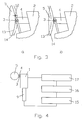
- FIG. 3a shows a detail of the engraving head 2 from FIG. 1 on an enlarged scale.
- the narrow gap 12 between the cylinder surface 13 of the gravure cylinder 5 with a precisely circular cylindrical shape and the measuring surface of the capacitive sensor 4 is clearly visible.
- Compressed air is applied to the air-blowing nozzle 11 in order to blow the impurities out of the gap 12 in the order of magnitude of 250 ⁇ m.
- Dashed lines indicate an out-of-roundness 14 of the cylinders 5 as a deviation of the cylinder surface 13 from the ideal circular cylindrical shape.
- the out-of-roundness 14 is drawn in solid lines in FIG. 3b and causes a tilting movement of the lifting platform 6 about the axis of rotation 7, ie an adaptation of the tool distance W of the engraving stylus 3.
- the air-blowing nozzle can also be used as an annular nozzle (not shown here) be formed, which extends around the capacitive distance sensor 4 and forms a kind of protective curtain made of compressed air around it and thus always keeps a clean measuring surface on the cylinder surface 13 free.
- the electronic control for tracking the tool distance of the engraving stylus 3 is shown schematically in FIG. 4 on the basis of the distance measured by the distance measuring element 4.
- the engraving head 2 with the piezoelectric drive 9, which is electrically connected to a drive control 15, is shown adjacent to the gravure cylinder 5.
- This drive control 15 is connected to an electronic circuit 17 for distance measurement via a control 16.
- the measured distance signal is compared as the actual value W Ist with a predetermined target value W Soll , which represents the ideal tool distance, and passed on to the controller 16 as a control signal.
- this control signal is processed as a control signal for the drive control 15 by a suitable time delay and signal amplification.
- This circuit thus forms a simple control loop in order to keep the tool distance W of the engraving stylus 3 constant with respect to the cylinder surface 13.
- the distance measuring element 4 is designed as a capacitive distance sensor.
- this can advantageously also be an inductive or optical distance sensor.
- a pneumatic distance sensor such as a dynamic pressure sensor known from sheet metal processing with lasers, can also be used for this purpose, in which case the air-blowing nozzle 11 is omitted, since the cleaning function is simultaneously taken over by such a sensor.
- an adjusting element 9 can instead of a piezoelectric Drive an electromagnetic drive in the form of an electrostrictive or magnetostrictive actuator can be used, as known from automotive technology in connection with so-called ABS systems.
- a precise servo motor or a hydraulic drive can also be used instead of the piezoelectric drive.
- the adjusting element 9 in the form of one of the drives mentioned above is normally linearly movable, since the lifting platform 6 only needs to perform a slight tilting movement.
- the engraving stylus 3 can be driven either in a conventional manner or by means of a piezoelectric drive unit which is controlled in a suitable manner.
Landscapes
- Engineering & Computer Science (AREA)
- Mechanical Engineering (AREA)
- Manufacturing & Machinery (AREA)
- Physics & Mathematics (AREA)
- General Physics & Mathematics (AREA)
- Manufacture Or Reproduction Of Printing Formes (AREA)
Abstract
Description
Die Erfindung betrifft eine Vorrichtung zum Gravieren von Tiefdruckformen nach dem Oberbegriff des Patentanspruchs 1.The invention relates to an apparatus for engraving gravure forms according to the preamble of
Eine solche Vorrichtung ist beispielsweise bekannt aus EP-B-0 262 634, die als Klischograph mit einem Gravierkopf ausgebildet ist, der auf einem Schlitten einen Halter mit einem Gravierstichel und einem Abtastorgan aufweist. Das fest mit dem Halter verbundene Abtastorgan hat eine Spitze, die die Oberfläche des Tiefdruckzylinders mechanisch abtastet und damit einen konstanten Abstand zwischen dem Gravierstichel und der Oberfläche gewährleisten soll. Um unerwünschte Schwingungen und Eigenresonanzen des Halters und des darauf befestigten Gravierstichels zu unterdrücken, wirkt eine mit einer Druckfeder versehene Dämpfungsanordnung auf das mechanische Abtastorgan. Dadurch soll verhindert werden, dass Streifenmuster im Druckbild, die im Fachjargon als "Jalousien" bekannt sind, bei der Gravur des Tiefdruckzylinders entstehen können.Such a device is known, for example, from EP-B-0 262 634, which is designed as a cliché with an engraving head which has a holder with an engraving stylus and a scanning element on a carriage. The scanning element, which is firmly connected to the holder, has a tip which mechanically scans the surface of the gravure cylinder and is thus intended to ensure a constant distance between the engraving stylus and the surface. In order to suppress unwanted vibrations and natural resonances of the holder and the engraving stylus fastened thereon, a damping arrangement provided with a compression spring acts on the mechanical scanning element. This is to prevent streak patterns in the printed image, which are known in technical jargon as "blinds", from occurring when the gravure cylinder is engraved.
Bei der mechanischen Abtastung des obengenannten Klischographes wird der Gravierstichel mit einer räumlichen Verschiebung nachgeführt, so dass es bei kurzwelligen Unebenheiten zu unterschiedlichen Abständen zwischen dem Gravierstichel und der zu gravierenden Oberfläche des Tiefdruckzylinders kommen kann. Aus diesen Gründen ist es für die Druckereien äusserst wichtig, die Unebenheiten und Unrundheiten des unbearbeiteten Tiefdruckzylinders in einem engen Toleranzbereich zu halten.During the mechanical scanning of the abovementioned cliché, the engraving stylus is tracked with a spatial shift, so that in the case of short-wave unevenness, there may be different distances between the engraving stylus and the surface of the gravure cylinder to be engraved. For these reasons, it is extremely important for the print shops to keep the unevenness and out-of-roundness of the untreated gravure cylinder within a narrow tolerance range.
Der vorliegenden Erfindung liegt nun die Aufgabe zugrunde, das Gravierwerkzeug auf einen konstanten Abstand zur Oberfläche des zu gravierenden Tiefdruckzylinders oder einer ähnlichen Druckform auch bei kurzwelligen Unebenheiten und grösseren Unrundheiten zu halten.The present invention is based on the object of keeping the engraving tool at a constant distance from the surface of the gravure cylinder to be engraved or a similar printing form, even in the case of short-wave bumps and larger out-of-roundness.
Diese Aufgabe wird durch eine Vorrichtung mit den Merkmalen des Patentanspruchs 1 gelöst.This object is achieved by a device with the features of
Die Erfindung beruht auf der Erkenntnis, dass das Abtastorgan der vorstehend erwähnten, bekannten Graviervorrichtung mit einem gewissen Druck auf die Oberfläche des Tiefdruckzylinders anliegen muss, um die Unebenheiten richtig abtasten zu können und die dadurch entstehenden Eigenschwingungen mittels einer Dämpfungsanordnung wieder unterdrückt werden müssen. Dadurch, dass erfindungsgemäss das Abtastorgan als berührungsloses Abstandsmessorgan vorgesehen ist, können die obigen Schwingungen schon von Anfang an nicht entstehen. Abgesehen davon weist die Spitze des bekannten Abtastorgans eine bestimmte Abtastfläche auf, die im Betrieb durch die Abnutzung allmählich grösser wird, und deshalb periodisch kontrolliert und nachgeschliffen werden muss.The invention is based on the knowledge that the scanning element of the above-mentioned, known engraving device has to bear a certain pressure on the surface of the gravure cylinder in order to be able to correctly scan the bumps and the natural vibrations resulting therefrom have to be suppressed again by means of a damping arrangement. Because the scanning element is provided as a non-contact distance measuring element according to the invention, the above vibrations cannot arise from the start. Apart from this, the tip of the known scanning element has a certain scanning area, which gradually increases in size as a result of wear and must therefore be checked and reground periodically.
Die Erfindung hat somit den Vorteil, dass die als Abstandsmessung durchgeführte Abtastung keinerlei Abnutzung unterworfen ist und deshalb keiner periodischen Kontrolle bedarf. Ferner können der Ort der Abstandsmessung und die Auflagestelle des Gravierstichels sehr nahe zueinander liegen oder sogar zusammenfallen. Dadurch haben auch kurzwellige Unebenheiten oder Unrundheiten des Tiefdruckzylinders keinen Einfluss mehr auf das Konstanthalten des Abstandes zwischen dem Gravierwerkzeug und der zu gravierenden Oberfläche. Ausserdem gewährleistet die berührungslose Abtastung eine äusserst schnelle und präzise Messung, so dass eine genaue Anpassung des Abstandes in örtlicher und in zeitlicher Hinsicht gegeben ist. Das bedeutet, dass zeitliche Verzögerungen, die üblicherweise bei der vorgenannten bekannten mechanischen Abtastung auftreten, völlig unterbleiben.The invention thus has the advantage that the scanning performed as a distance measurement is not subject to any wear and therefore does not require periodic checking. Furthermore, the location of the distance measurement and the contact point of the engraving stylus can be very close to one another or even coincide. As a result, even short-wave bumps or out-of-roundness of the gravure cylinder no longer have any influence on keeping the distance between the engraving tool and the surface to be engraved constant. In addition, the contactless scanning ensures an extremely fast and precise measurement, so that the distance is precisely adjusted in terms of location and time. This means that time delays that usually occur in the aforementioned known mechanical scanning are completely eliminated.
Weitere Vorteile der Erfindung ergeben sich aus den abhängigen Ansprüchen und aus der nachfolgenden Beschreibung, in welcher die Erfindung anhand eines in den schematischen Zeichnungen dargestellten Ausführungsbeispieles näher erläutert wird. Es zeigt:
- Fig. 1
- eine schematische Darstellung einer Graviermaschine mit einem berührungslosen Abstandsmessorgan,
- Fig. 2
- eine Frontansicht in Richtung des Pfeiles A in
Figur 1 auf den Gravierkopf, - Fig. 3
- eine vergrösserte Darstellung der
Figur 1 zur Verdeutlichung der Betriebsweise, und - Fig. 4
- ein Schaltschema der Steuerung des Werkzeugabstandes des Gravierstichels.
- Fig. 1
- 1 shows a schematic representation of an engraving machine with a non-contact distance measuring element,
- Fig. 2
- 2 shows a front view in the direction of arrow A in FIG. 1 on the engraving head,
- Fig. 3
- an enlarged view of Figure 1 to illustrate the mode of operation, and
- Fig. 4
- a circuit diagram of the control of the tool distance of the engraving stylus.
In den Figuren sind für dieselben Elemente jeweils dieselben Bezugszeichen verwendet und gelten erstmalige Erklärungen der Elemente für alle Figuren, wenn nicht ausdrücklich anders angegeben.The same reference numerals are used in the figures for the same elements and first-time explanations of the elements apply to all figures, unless expressly stated otherwise.
In Figur 1 ist eine Graviermaschine 1 mit einem Halter oder Gravierkopf 2 dargestellt, der einen Gravierstichel 3 und ein Abstandmessorgan 4 aufweist. Der Gravierstichel 3 dient in bekannter Weise dazu, Rasternäpfchen in der Oberfläche eines Tiefdruckzylinders 5 zu erzeugen. Das Steuersignal für die Auf- und Abbewegung des Gravierstichels 3 wird dabei von einem durch Abtasten einer Vorlage gewonnenen Bildsignal abgeleitet oder von einem digitalen Bildverarbeitungssystem abgegeben. Weitere Einzelheiten zur Funktion des Klischographes 1 sind auf dem einschlägigen Fachgebiet bekannt und werden daher hier nicht weiter erwähnt. Der Gravierkopf 2 ist auf einer Hebebühne 6 befestigt, die um eine Drehachse 7 drehbar gelagert und von einem sich gegen das Maschinengestell 8 abstützenden als piezoelektrischen Antrieb ausgebildeten Nachstellelement 9 durch eine Kippbewegung auf- und abbewegt wird. Die Drehachse 7 ist dabei ortsfest zum Maschinengestell 8 angeordnet, was der Einfachheit halber hier nicht weiter dargestellt ist. Diese Kippbewegung der Hebebühne 6 wird unmittelbar auf den Gravierkopf 2 übertragen und vom darauf befestigten Gravierstichel 3 mitgemacht. Je näher der Stützpunkt des Stössels 10 des Nachstellelementes oder piezoelektrischen Antriebes 9 zur Drehachse 7 angeordnet ist, je grösser wird die Kippbewegung und umgekehrt. Damit lässt sich das Übersetzungsverhältnis zwischen der Auslenkung des Stössels 10 und die Nachführung des Werkzeugabstandes W zwischen dem Gravierstichel 3 und der Oberfläche des Tiefdruckzylinders 2 entsprechend den jeweiligen Anforderungen einstellen.FIG. 1 shows an
In Figur 2 ist der Gravierkopf 2 in Frontansicht in Richtung des Pfeiles A der Figur 1 zu sehen. In diesem Beispiel ist das Abstandsmessorgan 4 als kapazitiver Sensor unmittelbar neben dem Gravierstichel 3 vorgesehen, so dass die Abstandsmessstelle und die Gravierstelle für die Rasternäpfchen nahe beieinander liegen. Durch geeignete Wahl des Messortes liegt dieser auf einer Rasterlinie, welche in der Bewegungsrichtung des Gravierstichels 3 liegt. Dadurch kann durch eine passende elektronische Verzögerung eine präzise Korrektur des Werkzeugabstandes W aufgrund des gemessenen Abstandes vorgenommen werden. Diese Verzögerung kann aus der Distanz zwischen dem Messort und der Bearbeitungsstelle des Gravierstichels 3 und aus der Bewegungsgeschwindigkeit des Gravierstichels 3 längs der Rasterlinie abgeleitet werden. Neben dem Abstandsmessorgan 4 ist eine Luftblasdüse 11 angeordnet, die auf der Oberfläche des Tiefdruckzylinders 2 angesammelten Staub und anhaftende Metallspäne von der gravierten Zylinderoberfläche wegbläst. Unterhalb des Gravierkopfes 2 kann zusätzlich eine nichtdargestellte Absaugeinrichtung vorgesehen sein, um die Verunreinigungen in der Form von Staub, Metallspänen und dergleichen wirksam entfernen zu können.In Figure 2, the
In Figur 3a ist ein Ausschnitt des Gravierkopfes 2 der Figur 1 vergrössert dargestellt. Deutlich ersichtlich ist der enge Spalt 12 zwischen der Zylinderoberfläche 13 des Tiefdruckzylinders 5 mit einer genau kreiszylindrischen Form und der Messfläche des kapazitiven Sensors 4. Die Luftblasdüse 11 wird mit Pressluft beaufschlagt, um die Verunreinigungen aus dem Spalt 12 in der Grössenordnung von 250 µm wegzublasen. Gestrichelt ist eine Unrundheit 14 der Zylinders 5 als Abweichung der Zylinderoberfläche 13 von der idealen kreiszylindrischen Form angedeutet. Die Unrundheit 14 ist in Figur 3b ausgezogen gezeichnet und bewirkt eine Kippbewegung der Hebebühne 6 um die Drehachse 7, d.h. eine Anpassung des Werkzeugabstandes W des Gravierstichels 3. Die Luftblasdüse kann auch als Ringdüse (hier nicht dargestellt) ausgebildet sein, die um den kapazitiven Abstandssensor 4 herumverläuft und eine Art Schutzvorhang aus Pressluft darum bildet und so stets eine saubere Messfläche auf der Zylinderoberfläche 13 freihält.FIG. 3a shows a detail of the
In Figur 4 ist die elektronische Steuerung zur Nachführung des Werkzeugabstandes des Gravierstichels 3 aufgrund des vom Abstandsmessorgan 4 gemessenen Abstandes schematisch gezeigt. Anliegend am Tiefdruckzylinder 5 ist der Gravierkopf 2 mit dem piezoelektrischen Antrieb 9 dargestellt, der mit einer Antriebssteuerung 15 elektrisch verbunden ist. Diese Antriebssteuerung 15 ist über eine Regelung 16 mit einer elektronischen Schaltung 17 für die Abstandsmessung verbunden. In der Schaltung 17 wird das gemessene Abstandssignal als Istwert WIst mit einem vorgegebenen Sollwert WSoll, welcher den idealen Werkzeugabstand darstellt, verglichen und als Regelsignal an die Regelung 16 weitergegeben. In der Regelung wird dieses Regelsignal durch eine passende Zeitverzögerung und Signalverstärkung als Steuersignal für die Antriebssteuerung 15 aufbereitet. Damit bildet diese Schaltung einen einfachen Regelkreis, um den Werkzeugabstand W des Gravierstichels 3 in bezug auf die Zylinderoberfläche 13 konstant zu halten.The electronic control for tracking the tool distance of the
Das Abstandsmessorgan 4 ist im obigen Beispiel als kapazitiver Abstandssensor ausgebildet. Mit Vorteil kann dieses jedoch auch ein induktiver oder optischer Abstandssensor sein. Auch ein pneumatischer Abstandssensor, wie beispielsweise ein aus der Blechbearbeitung mit Lasern bekannter Staudrucksensor, kann dazu verwendet werden, wobei in diesem Fall die Luftblasdüse 11 entfällt, da die Reinigungsfunktion gleichzeitig von einem solchen Sensor übernommen wird. Als Nachstellelement 9 kann anstatt eines piezoelektrischen Antriebes auch ein elektromagnetischer Antrieb in Form eines elektrostriktiven oder magnetostriktiven Stellgliedes verwendet werden, wie aus der Automobiltechnik in Zusammenhang mit sogenannten ABS-Systemen bekannt. Ein präziser Servomotor oder ein hydraulischer Antrieb kann ebenfalls anstelle des piezoelektrischen Antriebes eingesetzt werden. Das Nachstellelement 9 in der Form eines der obengenannten Antriebe ist normalerweise linearbeweglich, da die Hebebühne 6 nur eine geringe Kippbewegung auszuführen braucht.In the above example, the
Der Antrieb des Gravierstichels 3 kann sowohl auf herkömmliche Art wie auch mittels einer piezoelektrischen Antriebseinheit, die auf geeignete Weise angesteuert wird, erfolgen.The
Claims (12)
Applications Claiming Priority (2)
| Application Number | Priority Date | Filing Date | Title |
|---|---|---|---|
| CH274/95 | 1995-05-02 | ||
| CH127495 | 1995-05-02 |
Publications (2)
| Publication Number | Publication Date |
|---|---|
| EP0741008A2 true EP0741008A2 (en) | 1996-11-06 |
| EP0741008A3 EP0741008A3 (en) | 1998-05-13 |
Family
ID=4206591
Family Applications (1)
| Application Number | Title | Priority Date | Filing Date |
|---|---|---|---|
| EP96105870A Withdrawn EP0741008A3 (en) | 1995-05-02 | 1996-04-15 | Apparatus for engraving printing cylinders |
Country Status (1)
| Country | Link |
|---|---|
| EP (1) | EP0741008A3 (en) |
Cited By (2)
| Publication number | Priority date | Publication date | Assignee | Title |
|---|---|---|---|---|
| WO2004056568A3 (en) * | 2002-12-20 | 2005-01-13 | Giesecke & Devrient Gmbh | Method and device for producing intaglio printing plates and a printing plate produced in such a manner |
| EP1900517A1 (en) * | 2006-09-12 | 2008-03-19 | MDC Max Dätwyler AG | Apparatus for producing embossed structures on the surface of a cylinder |
Family Cites Families (3)
| Publication number | Priority date | Publication date | Assignee | Title |
|---|---|---|---|---|
| GB1498811A (en) * | 1974-03-01 | 1978-01-25 | Crosfield Electronics Ltd | Preparation of gravure printing cylinders |
| DE3201178A1 (en) * | 1982-01-16 | 1983-07-28 | M.A.N.- Roland Druckmaschinen AG, 6050 Offenbach | Device for adjusting a doctor in a rotary intaglio printing machine to the respective forme cylinder diameter |
| CH672458A5 (en) * | 1986-10-02 | 1989-11-30 | Daetwyler Ag |
-
1996
- 1996-04-15 EP EP96105870A patent/EP0741008A3/en not_active Withdrawn
Cited By (3)
| Publication number | Priority date | Publication date | Assignee | Title |
|---|---|---|---|---|
| WO2004056568A3 (en) * | 2002-12-20 | 2005-01-13 | Giesecke & Devrient Gmbh | Method and device for producing intaglio printing plates and a printing plate produced in such a manner |
| EP1900517A1 (en) * | 2006-09-12 | 2008-03-19 | MDC Max Dätwyler AG | Apparatus for producing embossed structures on the surface of a cylinder |
| WO2008031242A3 (en) * | 2006-09-12 | 2008-07-10 | Mdc Max Daetwyler Ag | Device for producing embossed structures in a surface of a cylinder |
Also Published As
| Publication number | Publication date |
|---|---|
| EP0741008A3 (en) | 1998-05-13 |
Similar Documents
| Publication | Publication Date | Title |
|---|---|---|
| EP2097261B9 (en) | Rotary printing press and method for adjusting a cylinder thereof | |
| DE102006008464B4 (en) | imprinting apparatus | |
| DE102016002765B3 (en) | Device with press, tool and tool protection system for the processing of sheet metal workpieces and adjustable distance means usable therefor | |
| EP2832546A1 (en) | Printing machine with print head control | |
| DE68927482T2 (en) | Positioning mechanism and procedure | |
| EP2092991B1 (en) | Die for a bending press, in particular a press brake and method for bending a workpiece | |
| EP0377796A2 (en) | Measuring and alignment device for a cylindrical grinding machine | |
| DE69104766T2 (en) | Cutting machine and cutting process with this machine. | |
| DE69413611T2 (en) | Method and device for adjusting the distance between a workpiece and a mask | |
| DE202007004717U1 (en) | Rotary press | |
| DE3821548C2 (en) | ||
| EP0925188B1 (en) | Method and device to control an engraving device | |
| DE2951532A1 (en) | DEVICE FOR MEASURING GEOMETRIC CHARACTERISTICS OF MECHANICAL WORKPIECES | |
| CH689669A5 (en) | An apparatus for engraving gravure cylinders. | |
| DE3914059C2 (en) | ||
| DE102019135740B4 (en) | Holding device with elastic spring element and pneumatic channel system; Placement head and placement machine and method for placing component carriers | |
| EP3808563A1 (en) | Computer-implemented method for controlling a screen printing machine as well as computer-controlled screen printing machine | |
| EP0603526B1 (en) | Method and apparatus for electric discharge machining | |
| EP1762818B1 (en) | Scanning head | |
| EP1528981A1 (en) | Cylinders of a web-fed printing press and printing unit | |
| DE19961869B4 (en) | Adjustment device, in particular for traverses with imaging devices for printing forms of printing presses | |
| DE102018103398B4 (en) | Pneumatically actuatable spring element for controlling the placement force acting on a component | |
| CH679536A5 (en) | ||
| EP1974854B1 (en) | Method for scanning the contours of openings in a spectacles frame and device for scanning the contours of openings in a spectacles frame for the peripheral grinding of spectacles lenses | |
| EP1187720A2 (en) | Method of operating an engraving machine |
Legal Events
| Date | Code | Title | Description |
|---|---|---|---|
| PUAI | Public reference made under article 153(3) epc to a published international application that has entered the european phase |
Free format text: ORIGINAL CODE: 0009012 |
|
| AK | Designated contracting states |
Kind code of ref document: A2 Designated state(s): DE FR GB IT |
|
| GBC | Gb: translation of claims filed (gb section 78(7)/1977) | ||
| PUAL | Search report despatched |
Free format text: ORIGINAL CODE: 0009013 |
|
| AK | Designated contracting states |
Kind code of ref document: A3 Designated state(s): DE FR GB IT |
|
| 17P | Request for examination filed |
Effective date: 19980630 |
|
| 17Q | First examination report despatched |
Effective date: 19990422 |
|
| GRAG | Despatch of communication of intention to grant |
Free format text: ORIGINAL CODE: EPIDOS AGRA |
|
| STAA | Information on the status of an ep patent application or granted ep patent |
Free format text: STATUS: THE APPLICATION IS DEEMED TO BE WITHDRAWN |
|
| 18D | Application deemed to be withdrawn |
Effective date: 20001101 |