EP0741032A2 - Dispositif de mesure de la densité réflective et système de contrÔle pour une machine à imprimer des bandes - Google Patents
Dispositif de mesure de la densité réflective et système de contrÔle pour une machine à imprimer des bandes Download PDFInfo
- Publication number
- EP0741032A2 EP0741032A2 EP96106538A EP96106538A EP0741032A2 EP 0741032 A2 EP0741032 A2 EP 0741032A2 EP 96106538 A EP96106538 A EP 96106538A EP 96106538 A EP96106538 A EP 96106538A EP 0741032 A2 EP0741032 A2 EP 0741032A2
- Authority
- EP
- European Patent Office
- Prior art keywords
- block
- web
- color
- image
- pixels
- Prior art date
- Legal status (The legal status is an assumption and is not a legal conclusion. Google has not performed a legal analysis and makes no representation as to the accuracy of the status listed.)
- Granted
Links
- 238000007639 printing Methods 0.000 title claims abstract description 67
- 238000000149 argon plasma sintering Methods 0.000 claims abstract description 52
- 239000011159 matrix material Substances 0.000 claims description 137
- 239000007787 solid Substances 0.000 claims description 28
- 238000010304 firing Methods 0.000 claims description 15
- 238000012545 processing Methods 0.000 claims description 15
- 238000005286 illumination Methods 0.000 claims description 10
- 230000007246 mechanism Effects 0.000 claims description 8
- 238000002310 reflectometry Methods 0.000 claims description 7
- 238000012546 transfer Methods 0.000 claims description 6
- 238000001579 optical reflectometry Methods 0.000 claims 1
- 240000007320 Pinus strobus Species 0.000 description 59
- 238000004458 analytical method Methods 0.000 description 54
- 239000003086 colorant Substances 0.000 description 22
- 238000012360 testing method Methods 0.000 description 21
- 238000005259 measurement Methods 0.000 description 14
- 239000000872 buffer Substances 0.000 description 11
- 238000000034 method Methods 0.000 description 11
- 238000012937 correction Methods 0.000 description 8
- 230000008569 process Effects 0.000 description 8
- 238000012935 Averaging Methods 0.000 description 7
- 230000000694 effects Effects 0.000 description 7
- 230000006870 function Effects 0.000 description 7
- 239000000428 dust Substances 0.000 description 6
- 238000010586 diagram Methods 0.000 description 5
- 230000001133 acceleration Effects 0.000 description 4
- 238000001739 density measurement Methods 0.000 description 4
- 239000000463 material Substances 0.000 description 4
- 239000002245 particle Substances 0.000 description 4
- 230000008901 benefit Effects 0.000 description 3
- 238000004364 calculation method Methods 0.000 description 3
- 230000008859 change Effects 0.000 description 3
- 238000009826 distribution Methods 0.000 description 3
- 238000003384 imaging method Methods 0.000 description 3
- 241000196324 Embryophyta Species 0.000 description 2
- 239000000654 additive Substances 0.000 description 2
- 230000000996 additive effect Effects 0.000 description 2
- 238000011109 contamination Methods 0.000 description 2
- 239000011521 glass Substances 0.000 description 2
- 230000003993 interaction Effects 0.000 description 2
- 238000012423 maintenance Methods 0.000 description 2
- 238000005406 washing Methods 0.000 description 2
- 229910052724 xenon Inorganic materials 0.000 description 2
- FHNFHKCVQCLJFQ-UHFFFAOYSA-N xenon atom Chemical compound [Xe] FHNFHKCVQCLJFQ-UHFFFAOYSA-N 0.000 description 2
- 229930091051 Arenine Natural products 0.000 description 1
- 241000287107 Passer Species 0.000 description 1
- 229920000995 Spectralon Polymers 0.000 description 1
- 229910000831 Steel Inorganic materials 0.000 description 1
- 238000003491 array Methods 0.000 description 1
- 239000003990 capacitor Substances 0.000 description 1
- 238000006243 chemical reaction Methods 0.000 description 1
- 238000012790 confirmation Methods 0.000 description 1
- 238000005520 cutting process Methods 0.000 description 1
- 238000011161 development Methods 0.000 description 1
- 238000005516 engineering process Methods 0.000 description 1
- 238000010191 image analysis Methods 0.000 description 1
- 238000009434 installation Methods 0.000 description 1
- 230000000670 limiting effect Effects 0.000 description 1
- 230000006855 networking Effects 0.000 description 1
- 230000003287 optical effect Effects 0.000 description 1
- 230000000737 periodic effect Effects 0.000 description 1
- 230000002028 premature Effects 0.000 description 1
- 238000002360 preparation method Methods 0.000 description 1
- 230000001681 protective effect Effects 0.000 description 1
- 230000003595 spectral effect Effects 0.000 description 1
- 238000001228 spectrum Methods 0.000 description 1
- 239000010959 steel Substances 0.000 description 1
- 238000003860 storage Methods 0.000 description 1
- 238000006467 substitution reaction Methods 0.000 description 1
- 230000001360 synchronised effect Effects 0.000 description 1
Images


Classifications
-
- B—PERFORMING OPERATIONS; TRANSPORTING
- B41—PRINTING; LINING MACHINES; TYPEWRITERS; STAMPS
- B41F—PRINTING MACHINES OR PRESSES
- B41F33/00—Indicating, counting, warning, control or safety devices
- B41F33/0036—Devices for scanning or checking the printed matter for quality control
- B41F33/0045—Devices for scanning or checking the printed matter for quality control for automatically regulating the ink supply
-
- B—PERFORMING OPERATIONS; TRANSPORTING
- B41—PRINTING; LINING MACHINES; TYPEWRITERS; STAMPS
- B41P—INDEXING SCHEME RELATING TO PRINTING, LINING MACHINES, TYPEWRITERS, AND TO STAMPS
- B41P2233/00—Arrangements for the operation of printing presses
- B41P2233/50—Marks on printed material
- B41P2233/51—Marks on printed material for colour quality control
Definitions
- the present invention generally relates to a method and apparatus for measuring reflective density of predetermined areas printed patterns of ink and also for using the measurements to control the application of printing ink by the press.
- Web printing presses of the type which print full color magazines and other printed material at high speeds generally have a number of printing stations, each of which prints a different color on the web as the web passes through the press. Such presses generally have multiple printing stations which generally print the colors cyan, magenta and yellow, as well as black.
- the quality of the printed matter is a function not only of the proper registration of each of the colors by the respective printing stations, but also by the amount of ink and its resultant pattern of distribution that is printed for each color by the printing stations.
- ink zone control mechanisms commonly referred to as "keys” that are spaced across the width of the printing press, typically at approximately every 1 to 2 inches, depending upon the press type, and these keys effectively determine zones that regulate the amount of ink that is available to be ultimately transferred to a web. For each color that is being printed, there may be very little or a relatively large amount of ink transferred at each key location of each printing station, depending upon the perceived color in the image that is printed.
- Another object is to provide such an improved reflective density measuring apparatus which utilizes a CCD matrix sensor and a strobe for acquiring matrix images of the web, including a test print area containing various types of blocks of the colors being printed by individual printing stations of a printing press and analyzing the acquired images to obtain the reflective density value for each of the blocks.
- Still another object of the present invention is to provide such an improved apparatus which is capable of performing the reflective density analysis on the acquired pixel data on a real time basis, with the press running at high speed.
- test print areas are printed on the web which include color blocks of each color printed by a color station and wherein the test print areas are printed adjacent each of the key locations of the printing press so that separate reflective density values can be determined for each color at each key location thereby providing extremely reliable and accurate reflective density values.
- the test print area can include solid color blocks as well as screen color blocks, combination screen and solid color blocks and multiple solid color blocks that have been overprinted.
- Another object of the present invention is to provide such an improved apparatus which acquires a pixel data image during operation of the press, splits the image into three separate channels of red, green and blue, digitizes and analyzes the resultant images for each channel to provide an accurate reflective density value for the colors of cyan, magenta, yellow and black that are printed.
- Still another object of the present invention is to provide such an improved apparatus which is extremely reliable and accurate in determining reflective density values, because of the extremely sophisticated compensation and calibration techniques that are utilized by the apparatus.
- a corollary object lies in the provision for compensating for variation in intensity and color temperature of a particular strobe firing, as well as compensating for any discontinuity in distribution of light from the strobe on the web from which the image is acquired.
- Another corollary object lies in the provision for calibrating the digitizing portion of the apparatus to minimum and maximum reflectivity values using highly reflective i.e., white and highly nonreflective, i.e., black, certified standards to insure consistency of the calibration over time.
- a related object lies in the provision for providing digitized images of the analog image acquired by a CCD matrix sensor and analyzing the digitized images on a pixel by pixel basis during various operations of the apparatus. Such analysis enables the apparatus to ignore dust spots and other blemishes on a virtually pixel by pixel basis during various analyses that are made by the apparatus, as well as provide geometric measurement of the size of shapes and screens contained in acquired images.
- the present invention is directed to an apparatus for determining reflective density values of each color of ink that is printed on a web, preferably a paper web, by a web printing press of the type which has a number of printing stations, each of which is adapted to print impressions of an individual color.
- Full color printing presses generally print cyan, magenta and yellow, in addition to black.
- the apparatus embodying the present invention is adapted to produce the reflective density values for each of the colors in a reliable and accurate manner in real time, while the web is moving at high speed during a printing operation.
- the apparatus is adapted to produce the reflective density values by acquiring digitized images of the moving web using a stroboscopic illumination and thereafter analyzing the digitized images in various ways by examining the intensity of individual pixels of the image.
- the apparatus operates to acquire digitized images even while the press is running at speeds in excess of 3000 feet per minute and the reflective density values for each measurement can be produced in real time.
- the apparatus ups a multiple color CCD matrix sensor which acquires a matrix image and which has an internal means such as a prism which separates or splits the light into the red, green and blue components which are then processed in separate channels.
- each matrix image that is acquired by the multiple color CCD matrix sensor produces a separate channel of the colors red, green and blue and these channels correspondingly measure the reflective density of the printed ink colors of cyan, magenta and yellow, respectively.
- the sensor may have other types of internal means for separating the light into the red, green and blue components, such as a mosaic filter or a striped filter, for example.
- the present invention provides reflective density measurements that are accurate and reliable as a result of automatic calibration, and is adapted to convert reflective density values to substantially the same readings that are measured by a densitometer. While the densitometer readings theoretically range between 0 and approximately 3, with the higher number representing minimum reflectivity and the lower number representing 100% reflectivity, the working range is generally within approximately 0.5 and 2.5, with the 2.5 value representing the darkest black that is generally capable of being printed.
- the apparatus utilizes certain test print areas that may include several sets of small solid color blocks of cyan, magenta, yellow and black.
- the color block sets are printed across the width of the web at specific locations associated with the ink zone adjusting control mechanisms (often referred to as keys) of the printing press.
- the test print area can include sets of solid color blocks as well as sets of screen color blocks, combination screen and solid color blocks and multiple solid color blocks that have been overprinted.
- the control mechanisms adjust the ink feed in zones that extend across the web.
- the mechanism varies the quantity of the ink that is present and available to be ultimately transferred to the web during a printing operation.
- the mechanisms are spaced apart from one another approximately 1 to 2 inches, so that for a 38 inch wide press, there are approximately 24 zones.
- the apparatus of the present invention utilizes print test areas at each key location so that reflective density can be measured every 1 to 2 inches.
- each of the print test areas comprise color block sets which contain rectangular color blocks that are adjacent one another, with each color block set preferably having seven color blocks, including color blocks of black, blue, magenta and yellow in a preferred sequence.
- the color blocks are sized relative to the digitized image that is acquired so that a well placed image acquisition will include all seven color blocks which will necessarily result in at least one color block of each color including black.
- the digitized image is preferably comprised of 760 pixels by 480 pixels, with each pixel having an intensity value that can vary between 0 and at least 255.
- the correlation between the analog intensity value and digital density vlaue can be either linear or nonlinear.
- the white level is preferably set at an intensity value of greater than 200 and less than 255 and the black level is preferably set to have an intensity value of greater than 0 and less than 63.
- the white level is set by acquiring an image of a certified white standard (preferably 99% reflective), and the black level is set by acquiring an image of a certified black standard (preferably 2% reflective).
- the apparatus also compensates for variations in the intensity and color temperature of light produced during individual firings of the strobe units which can be as much as 5%. This is done by measuring the illumination of each firing of the strobe units to yield a correction value which is used in such compensation.
- the apparatus also compensates for any discontinuity of illumination across the area of the field of view of which the image is being acquired, and is referred to as light field discontinuity compensation. This light field discontinuity compensation data is stored in memory for use in compensating for such unevenness during operation.
- the apparatus compensates for such light scattering characteristics.
- the calibration and compensation for the light scattering and light discontinuity variations, and strobe illumination variations, are important in producing an accurate reflective density value during operation.
- the apparatus includes analysis routines which insure accurate and reliable performance correcting for pixels that are not within intensity levels that are expected and performing analysis of measured values to provide a reliable resulting reflective density value.
- FIG. 1 shows a block diagram of the apparatus embodying the present invention, it includes a CCD matrix sensor 30 having a lens 32 with a nozzle structure 34.
- the CCD matrix sensor 30 is adapted to acquire matrix images of a web 36 that is wrapped around a web support roller 38 so as to present the side of the web having indicia printed thereon so that the CCD matrix sensor 30 can acquire matrix images of portions of the web.
- a pair of strobe units 40 are provided adjacent to the CCD matrix sensor 30 which direct illumination toward the web from opposite sides and illuminate the area of the web 36 from which matrix images are acquired by the CCD matrix sensor during operation. The strobe units 40 effectively freeze the web so that matrix images can be acquired even though the web 36 may be traveling at high speed.
- the CCD matrix sensor 30 and strobe units 40 as well as a strobe power supply and trigger module 42 and a cable interface and pixel data amplifier 44 are shown to be within a dotted line 46 which represents a carriage structure having an imaging head which is adapted to traverse the width of the scanner roll and beyond for the purpose of acquiring matrix images of the web.
- Another dotted line 48 represents the portion of the apparatus which is mounted on the sensor module.
- An encoder 50 is also interconnected with the press and measures the running speed of the press and is necessary to synchronize circumferential (the fire angle) so that the matrix images are acquired at the correct time to obtain the test print area in the view of the CCD matrix sensor.
- a motor 52 is also mounted on the press so that it is adapted to drive the carriage back and forth to accurately control the position of the CCD matrix sensor.
- the motor 52 is preferably a stepping motor driven by a driver 54 which receives signals via lines 56 from a controller 58.
- the apparatus preferably includes a cabinet which contains the components and circuits that are shown near the bottom of FIG. 1.
- the motor controller 58 is connected to a 16 bit bus 60 via bus connection 62 which is similar to other bus connections to other components, including a fire control 64 which receives the encoder signals from the encoder 50 via lines 66 and which provides output signals to the strobe control 64 via lines 68 which also extend to a pixel data memory 70 which is adapted to receive the digitized images and perform some of the analysis steps with respect to the data in the digitized images.
- bus connection 62 which is similar to other bus connections to other components, including a fire control 64 which receives the encoder signals from the encoder 50 via lines 66 and which provides output signals to the strobe control 64 via lines 68 which also extend to a pixel data memory 70 which is adapted to receive the digitized images and perform some of the analysis steps with respect to the data in the digitized images.
- a input/output (I/O) control 72 provides control for operation of the pixel data memory, the CCD matrix sensor, strobe control 64 and motor control portions of the apparatus.
- Lines 74 extend from the I/O control 72 to the strobe control 64 for controlling the synchronization of the firing of the strobes and acquiring of the matrix image by the CCD matrix sensor, the latter functionality being carried out by data that is sent over lines 76.
- the I/O control 72 also is interconnected with an analog-to-digital converter 78 via lines 80 and the I/O control 72 receives sensor information from the sensor module 48 via lines 82, as well as data relating to the operation of the pixel data memory 70 via lines 84.
- pixel data memory processor 86 for the pixel data memory 70 and it is interconnected with the pixel data memory 70 by lines 87.
- the A-to-D converter 78 which converts the analog matrix image acquired by the CCD matrix sensor to a digitized image in either a linear or nonlinear manner is interconnected with the pixel data memory 70 by lines 73.
- the converter 78 can be of the type which has a 32 bit processing capability. It should be understood that intensity levels from 0 to 255 for three colors occupies only 24 of the 32 bits, and therefore 2 additional bits could be utilized for the three colors to provide 10 bit resolution, i.e., 1024 intensity levels.
- the main processing capability is performed by a CPU 88 and an Ethernet network card 90 is also provided for networking multiple apparatus.
- the sensor module 48 contains a number of sensors, including three end-of-travel (EOT) sensors 91 which provide signals indicating that the carriage has moved to a location that is at or near the end of its travel and which provides signals via lines 82 to the I/O control to stop the motor 52, further operation of which could cause damage to the apparatus.
- EOT end-of-travel
- the CCD matrix sensor 30 provides analog signals of the acquired matrix image to the amplifier 44 via lines 93 and control signals for firing the strobes 40 are provided via lines 94.
- FIG. 1 While most of the operation of the apparatus is carried out by that shown in the block diagram of FIG. 1, it should be understood that the block diagram of FIG. 1 is only a part of a total installation on a printing press.
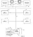
- Apparatus embodying the present invention is adapted to measure the reflective density and geometric measurements of print test areas for a complete press that generally involves printing on both sides of a web. It is also adapted to measure the reflective density of print test areas on two sides of two webs, such a system is shown in FIG. 2., which has four of the apparatus shown in FIG. 1, identified at 95, a control processor 96, a work station 98 for each web, with each work station having a monitor 99 and a keyboard 100.
- the work stations 98, individual apparatus 95 and control processor 96 are interconnected with an Ethernet network 101, and the control processor 96 may have a network 102 to link the apparatus to the printing establishment network.
- the control processor includes a central message passer (CMP) module 103 which operates to communicate messages from each component on the network 101 to another of the components. Thus, all messages from any processor to any other processor are controlled by the CMP 103.
- the apparatus also has a hard disk 104, a floppy disk 105 and a modem 106 connected to the control processor 96. Data relating to the status and operation of the apparatus can be stored on the hard disk 104, and data can be loaded and unloaded using the floppy disk.
- the modem 106 permits long distance diagnostic and maintenance work to be done on the apparatus.
- the CPU 88 of the apparatus of FIG. 1 is also a 486 microprocessor. As will be hereinafter described, there are microcode operations that are performed in the pixel data memory processor 86 which could be carried out by the CPU 88. Similarly, there may be functional operations performed by a particular component in FIG. 1 that may be carried out in other components. It is also expected that as the speed of processing continues to increase through advances in computer technology, fewer microprocessors may be necessary than are shown in FIG. 1.
- the present invention essentially involves the implementation of concepts that are described herein, including particular routines and subroutines that are described herein which implement the invention as claimed. While unquestionably essential in that it must perform the calculations to carry out the routines in a very rapid manner, the parti-cular hardware configurations may appear to be quite different from that shown in FIG. 1. For example, certain subroutines can be carried out in dedicated hardware.
- the apparatus utilizes test print areas that are printed on the web as shown in FIGS. 3, 3A, 4 and 5.
- FIG. 3 illustrates a trap target block 108 that is made by overprinting portions within the target block with ink combinations of the colors of magenta, cyan and yellow.
- FIG. 3 also has block sets 110 and 111 which are a combination of screen and solid portions.
- One of the sets 110 and 111 preferably has a 50 percent screen portion and the other a 75 percent screen portion. It should be understood that the screen portion is produced by printing predetermined sized dots in the screen area, and the screen may not appear exactly as shown in FIG. 3A.
- FIGS. 4 and 5 do not include the trap target block or combination screen and solid blocks, and particularly illustrate solid color block sets 112 that are used for determining the reflective density of the various color blocks that are a part of the set.
- Two of the color block sets are shown in FIG. 3, and an enlarged single color block set is shown in FIG. 4.
- FIG. 5 shows a reproduction of a portion of a printed page which includes five color block sets located near the bottom gutter below a line 114 which represents the bottom of a printed page of a magazine having one page that is approximately 8 inches wide as determined by a left edge 116 and a fold line indicated by the dotted line 118.
- the reproduction in FIG. 5 is approximately 80% of normal scale.
- FIG. 3 it also has the line 114 which represents the bottom of the printed matter of the page, the left edge 116 as well as a line 120 which represents the beginning of the printed matter for the following page.
- the printed matter is indicated generally by the hatched lines and is identified at 122.
- Each of the color block sets comprises seven color blocks located adjacent one another and each color block set 112 is positioned adjacent a control zone of the press which in FIG. 3 is shown to be on centers of 1.565 inches.
- the area between the lines 114 and 120 represents a gap 124 which contains indicia such as the color block sets 112 as well as other indicia for measuring and controlling cut lines and register control, for example.
- FIG. 5 illustrates arrows 126 as well as small lines 128 which are used to control cutting and forming of magazines and the like by the press.
- the set comprises seven color blocks of the colors cyan, magenta and yellow, as well as black. While the particular number and type of color blocks may vary from the seven shown, the number illustrated in the color block set of FIG. 4 has proven to be an effective number. More particularly, there is a black color block 130 located in the center, a cyan color block 132 to the right of the black color block and at the left end, a magenta color block 134 is located adjacent the cyan, and a yellow color block 136 is positioned adjacent to the black color block and at the right end.
- the black color block 130 has a tab 131 in the upper right corner as shown in FIG.
- the tab is located at a different corner in sequence for each color block set that is printed on the web as shown in FIGS. 3 and 5.
- the tabs provide information as to which color block set has been located, and enables the apparatus to determine if a color block set has been skipped during a pass of the CCD matrix sensor. It should be understood that smaller or larger sized color blocks may be used.
- the CCD matrix sensor 30 is positioned close enough to the web 36 that it obtains a matrix image that is approximately 500 thousandths by 380 thousandths of an inch.
- a rectangle 138 represents the approximate size of the matrix image that is acquired by the CCD matrix sensor 30 relative to the size of a color block set 112.
- This physical size produces a matrix image, which when digitized results in a matrix of individual pixels of 760 pixels by 480 pixels.
- the apparatus actually produces three of such matrix images, one for each of the colors of red, blue and green. With such a physical to pixel ratio, each pixel represents approximately 0.0006 inches.
- This ratio enables the apparatus to determine the shape and size of printed objects, including the size of dots printed in various screens, and particularly the dots that are printed in screen targets used for calculating print contrast and dot gain.
- their measurement in pixels is approximately 60 in width by 112 pixels in length and a single solid color block 136 is shown in FIG. 6.
- the outer boundaries of the color block 136 shown in FIG. 6 include a top end 140, a bottom end 142, a left end 144, a right end 146 and the tab 131.
- combination screen and solid blocks 110 and 111 The shape of the combination screen and solid blocks 110 and 111 is shown in FIGS. 3 and 3A. It should be appreciated that the solid and screen portions are adjacent one another in the circumferential direction of the web, rather than adjacent one another in the transverse direction, i.e., left and right as viewed in FIG. 3.
- a combination block 110 that has a 75 percent screen which is used to determine print contrast
- an image of the block 110 can be acquired and the size of the individual dots can be accurately measured as a result of the aforementioned physical to pixel ratio. This enables the apparatus to measure dot gain and print contrast by geometric measurement of the pixels of the known blocks.
- % print contrast 100 x (D(s) - D(t))/D(s) where D(s) is the major filter density of the solid and D(t) is the major filter density of the screen.
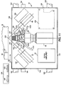
- FIG. 11 With respect to the carriage mechanism 46, it is shown in more detail in FIG. 11 and comprises an enclosure having outer walls 148, which enclosure holds the CCD matrix sensor 30 and strobe units 40. While the illustration of FIG. 11 is greatly simplified, the strobe units 40 are shown to have collimating lenses 150 positioned near the output and direct the center of the strobe light to a point 152 that is also coincident with the center line of the CCD matrix sensor 30. Thus, the strobe illuminates the area of the image on the web 36. The light from the strobe units exits the wall 148 through transparent windows 154 that are located adjacent an opening through which the CCD matrix sensor nozzle 34 extends.
- Capacitors 156 are positioned adjacent the strobe units 40 and a power supply 158 for the strobe units is positioned in the lower right corner as illustrated. While the top of the enclosure is not illustrated, it should be understood that it is completely enclosed and preferably substantially sealed from the exterior so that dust particles cannot be admitted into the interior thereof. In this regard, the only opening is the opening in the end of the cone 34 which is air purged of the CCD matrix sensor 30 so that the matrix images can be acquired of the web 36.
- the carriage structure is moved laterally relative to the web, i.e., left and right as indicated by the arrows 160 by moving along a pair of rails 162 that are - associated with cooperative mounting structures (not shown) on the underside of the carriage 46.
- the carriage is moved laterally by a belt drive 164 that is connected to a drive sprocket or the like connected to the motor 52 of FIG. 1.
- the exact structure of the rails 162 and belt 164 is well known to those of ordinary skill in the art and the particular structure that is used to accomplish the transverse movement of the carriage along the rail or comparable structure is not considered to be a novel feature of the present invention.
- the carriage 46 is adapted to move laterally along the web 36 and also may extend to the end of the web 116 as well as beyond the edge onto the web support roller 38 itself.
- the carriage 46 may also be moved to an enclosure 166 that is schematically illustrated and which contains a white standard 168, and a black standard 170 which may be located near the end of the range of travel of the carriage 46. While not illustrated in FIG. 11, it is preferred that the standards 168 and 170 be contained in a dust free environment which means that the enclosure 166 is substantially sealed except for those times when images are acquired of the standards. It is preferred that the normal end of travel not extend to the enclosure 166, but that if images are to be acquired of the standards, then the carriage can be moved farther to the left and suitable actuation being accomplished to open substantially sealed doors or the like to expose the standards 168 and 170 so that images of them can be acquired.
- the operation end of travel sensor provides a signal indicating that the carriage 46 has moved to the end of the web support roller 38.
- the ACC end of travel sensor indicates the end of travel at the enclosure 166, with the opposite end of the roller 38 being controlled by the end of travel sensor 91.
- photodiodes 172 are provided adjacent the collimating lenses 150 and are in position to provide a signal that is proportional to the output of the strobe units 40 and this signal is part of the information that is transmitted to the A-to-D converter 78 via lines 93 for use in adjusting the intensity values of pixels that are a part of the acquired digitized image after the analog matrix image has been digitized.
- the CCD matrix sensor 30 is of the type which includes an internal prism that splits the light into three paths or channels, i.e., red, green and blue.
- each acquired matrix image provides three matrix images, one for each of these colors and the three matrix images are sent to the A-to-D converter 78 where they are digitized into three separate digitized images.
- the intensity values of the individual pixels of the digitized image will be low for the channel in which the ink color is of interest.
- Such sensors may be manufactured to be responsive to individual colors of red, green and blue, or there may be filters attached to them to make them responsive to such individual colors.
- red, green and blue components of the signal represent an additive process for producing the full range of the color spectrum
- the printing of colors on a web is a subtractive process and there is a relationship between the CCD matrix sensor channels and the ink color being processed.
- yellow takes away one of the channels, as does magenta and cyan take away one of the other two channels.
- Black is a color that takes away all three channels. Yellow is the absence of blue, so a blue channel of perfect yellow ink would yield no blue and 100% red and green. With cyan there is no red, so the red channel would be zero, and the green and blue channels would be approximately 100%.
- the magenta channel will have no green, but approximately 100% red and blue.
- Black is the absence of all 3 channels, so that perfect black would yield no red, green or blue.
- yellow is printed on top of cyan, the blue and red channels are taken away and green is left.
- ink is printed, it is a subtractive process, whereas with light when red and green are added, yellow is obtained which is an additive process.
- the present invention it is necessary to only look at one channel at a time and if its signal level is low, it will reveal a reflective density valuation because reflective density is the lack of reflectance of a color.
- a high density ink is very dark which means that it reflects less of that color.
- the reflective density is what is being determined by the present invention and it is only necessary to analyze the three channels individually to determine the reflective density of each of the three colors of cyan, magenta and yellow. Black reflective density is determined by a single channel or the average of all three channels.
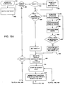
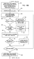
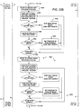
- a start block 200 causes initialization of the system as shown by block 202 and this results in starting of the main loop (block 204) which results in a multiplexing function (block 206) which switches among various cases which control various aspects of the operation of the apparatus.
- the routine inquires whether it should calibrate the CCD matrix sensor (block 208) and does so during start-up (block 210). If the CCD matrix sensor has been recently calibrated, the routine then inquires if the edge of the web has been found (block 212) and if it needs to be found, then it executes a routine for finding the web edge (block 214).
- the routine returns to the start of the main loop 204. If there is no need to find the web edge, i.e., it is known, then the routine sequences to case 3 to determine whether data should be acquired (block 216) and if so, a determination is made as to whether reflective density data should be acquired or light scattering data acquired (block 218). If the press run is new so that light scattering data has not been acquired, the apparatus acquires light scattering data (block 220).
- the apparatus is set up to acquire reflective density data (block 222).
- the apparatus sequences the CCD matrix sensor to acquired matrix images at each key location sequentially across the web, digitized the matrix image and performs an analysis to determine the content of the degree of whiteness in the acquired digitized image, with all pixels in the digitized image being measured with respect to a threshold white value to determine the amount of light scattering compensation that should be performed with respect to each particular image. This is a function of a printed matter adjacent to each key.
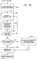
- the routine inquires as to whether the press is stopped (block 226). If the press is stopped, then the routine inquires as to whether it is time to calibrate the CCD matrix sensor again and if it is, then the CCD matrix sensor is again calibrated (block 230). If it is not time to calibrate, the routine returns to the start of the main loop 204. It is generally advisable to recalibrate the CCD matrix sensor if the press has stopped for a period in excess of 10 minutes. If the press has not been stopped, then the routine inquires as to whether there has been an operation request made (block 232). If such a request has been made, several service operations may be carried out (block 234).
- Service operations or normal printing operations may include a view request where an operator may request that an image be acquired of a particular location on the web that may be independent of the images that are acquired of the color block sets.
- a press operator may wish to monitor a particularly critical area of an impression, such as a highlight, for example.
- Such an operation can be carried out generally concurrently with many of the other data acquisition operations by controlling the CCD matrix sensor to go to a particular location and acquire the data when time permits and then return to the normal operation of the apparatus.
- An operator can also request calibration of the CCD matrix sensor which is determined by the operator and is done independently of the calibrate CCD matrix sensor routines that occur during operation of the routine, such as shown at blocks 210 and 230.
- the apparatus can operate in one of several modes including idle, start-up, sample and maintain.
- idle mode the apparatus is ready to acquire data, but is not commanded to do so.
- the apparatus may be ready to operate, but once the CCD matrix sensor is calibrated, for example, it cannot acquire light scattering data until printed matter appears on the web which can be analyzed for light scattering compensation.
- the apparatus can determine the edge of the web before printed matter appears, and can determine the width of the web and then the system waits for printed matter to appear. Once the printed matter appears, the operator can change to a start-up mode.
- the CCD matrix sensor does a slow traverse to acquire light scattering data that is used to compensate for the light scattering.
- the slow passes for acquiring light scattering data is necessary because more data is analyzed, i.e., every pixel of the 760 by 480 pixel matrix is analyzed to determine the light scattering compensation.
- Once several passes are made for acquiring light scattering data i.e., preferably approximately 6 passes, the data that is acquired is averaged over the 6 passes to provide a reliable light scattering compensation factor for use in determining reflective density.
- light scattering compensation data must be acquired for each of the three channels of red, green and blue, and these three compensation factors are generated for each key location across the web.
- the resulting light scattering compensation factors are stored in memory for use during the printing of the job. It should be understood that real time scattering correction on an acquisition by acquisition basis is possible. To carry out such functionality, an inline dedicated processor may be required.
- the apparatus After the start-up mode, the apparatus is switched into a run mode where reflective density data is acquired by taking a preferably minimum number of passes of data approximately every 500 impressions. These reflective density values are stored in memory. In the maintain mode, the apparatus takes multiple passes of data approximately every 500 impressions and also stores that data in memory for use in the preparation of press run reports.
- the CCD matrix sensor is traversed across the web.
- the apparatus can acquire a digitized image of each color block and calculate reflective density in less than approximately 70 milliseconds so the traverse speed is synchronized to the web speed of the press so that the CCD matrix sensor moves approximately 1-1/2 inch during each revolution.
- the apparatus can acquire a digitized image every revolution of the impression roller so that during every second, there are approximately 12 locations of the color keys from which digitized images are acquired and analyzed.
- the reflective density data that is acquired during the sample and maintain modes provide a detailed record of the color densities of each of the colors being printed approximately every 500 impressions throughout the course of the printing run.
- Such data can be used to generate reports which provide frequent "snapshots" of the reflective density and therefore provide a history of the print run which can be used to satisfy the customer about the quality of the printing.
- the apparatus of the present invention essentially eliminates the need to save samples of a press run for the reason that the reflective density data is accumulated in memory and can be printed out after the job in the form of a report which indicates the quality of the printing essentially approximately every 500th impression.
- the apparatus has three lines in which the customer can identify the job including a six digit job number, a three digit form number, a three digit run number, a job name, job description and publication code.
- the report also provides useful information for a press house in that it provides a record of changes that were made to the keys from the beginning until the end, including the corrections that were made in the course of reaching the point where the press was stable. This can be used as a teaching tool to keep pressmen from making unnecessary corrections in the beginning of the run. It is common for another piece of equipment in a press house to provide preset values for keys from which corrections can be made to reach a stable press operation. It is common for pressmen to make initial corrections that prove to be unnecessary in that they are premature and reflect reflective density key settings that are not stabilized before such corrections are made.
- the carrier 46 can be moved to the left as shown so that the CCD matrix sensor 30 is in position to acquire a matrix image of either the white standard 168 or the black standard 170 for the purpose of calibrating the CCD matrix sensor and the digitizing portion of the apparatus.
- the standards are of a generally flat circular shape as shown in FIGS. 10A and 10B and are Spectralon color standards manufactured by Labsphere, Inc., P.O. Box 70, North Sutton, New Hampshire 03260. The standards are calibrated and are measured for 8 degrees/hemispherical spectral reflectance factor using a double beam ratio recording integrating sphere reflectometer.
- the standards 168 and 170 be housed in a protective enclosure 166 so that dust particles will not be present on the surface of the standards which can dramatically affect the intensity readings that are obtained for each pixel during the image acquisition by the CCD matrix sensor 30. It is for this reason that the carriage preferably has a mechanism that will open a cover or the like to enable the CCD matrix sensor to acquire a matrix image of the standards 168 and 170.
- the CCD matrix sensor acquires matrix images of the black and white standards and the matrix image is digitized so that each pixel of the digitized image has an the intensity level that can be within the possible range of 0 to 255.
- the calibration process sets the intensity value of the black standard to the value of preferably approximately 8 and sets the value for the white standard at approximately 240. This is accomplished on three independent channels of red, green and blue and all are handled individually.
- the carriage 46 is moved to the location of the standards so that matrix images can be acquired.
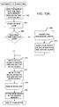
- FIGS. 13A through 13C which is a flow chart for obtaining the white level and the black level
- the motor 52 (FIG. 1) is moved to its zero position which is the end of travel limit (block 202) of FIG. 13A and the pixel data memory 70 (FIG. 1) is tested and any bad data values are removed.
- the main loop is started (block 204) and the routine determines if it is the second time through the loop (block 206). If it is the first time through the loop, it merely determines whether the pixel data memory 70 is not nonfunctional. If it is the second time through the loop, then the routine adjusts the horizontal phase (block 208). This is done to make sure that the acquired matrix image includes the active video portion rather than timing information such as the horizontal pulse. The phase is adjusted so that active video is acquired.
- the routine checks for spots (block 210) on the standards as well as the strobe glass window 154.
- spots block 210 on the standards as well as the strobe glass window 154.
- FIGS. 10A and 10B illustrate two matrix images of the white standard 168 which has spots 212, 214 and 216.
- the matrix image shown in FIG. 10B is an exaggeration of what would be acquired after having moved the CCD matrix sensor 0.020 to 0.030 inches relative to the matrix image of FIG. 10A.
- the apparatus is adapted to logically determine that the spot 216, by virtue of having moved to the right in FIG. 10B relative to its location in FIG. 10A was a result of dust being located on the window 154 rather than on the standard 168 itself. Since many of these spots will detrimentally affect the accuracy of the standards, the standards and the glass windows 154 should be cleaned when such spots are detected.
- the apparatus of the present invention also ignores the pixels where the spots are located during its analysis and does so by measuring the pixel intensity of each pixel and disregards the pixel if it is not within predetermined threshold values.
- the matrix image is of the black standard, then the reflectance should be very low and a spot that has an intensity value above 40, for example, would be thrown out.
- the matrix image is of the white standard, then reflectance values below approximately 200 would be thrown out or disregarded during the calculation of the average of the pixel values for that standard.
- the routine causes the CCD matrix sensor to be moved to the black standard (block 212) and acquires a matrix image which is digitized and set to a predetermined level, which is preferably approximately 8.
- the CCD matrix sensor and associated components acquire successive digitized images until the level is at 8 plus or minus .25 pixels. If not within the range, there are adjustments made until that tolerance is met, and it may require about 8 acquisitions.
- the carriage 46 then moves the CCD matrix sensor to acquire a matrix image of the white standard 168 and the system is set to have the white level at 240 plus or minus 0.95 (block 214). There are successive digitized images acquired of the white standard until the white level is also within this tolerance.
- the routine returns to the start of the main loop (block 204) and the routine is repeated twice more, for a total of three times.
- the apparatus returns to the black standard and acquires 10 digitized images which it averages to provide a value for use by the apparatus. It then does the same for the white standard and the averages are stored in memory 218.
- the values that are used by the apparatus consists of only the average of the 10 digitized images for each standard that are acquired after the last pass through the routine.
- the reason for using these values is that there is an interaction between the black level and the white level, particularly when the black level is set to 8 and the white level to 240. Because of the slight interaction with each other, it is desirable to iteravely set the levels by going back and forth between the standards so that the resulting levels are accurate.
- the calibration routine is run when the power to the apparatus is initially turned on, and is required to recalibrated more frequently until the apparatus reaches stable running temperature. However, if the press is stopped, for example, the CCD matrix sensor is recalibrated to make sure that the levels are accurately set. Also, the calibration only requires approximately 30 seconds to one minute to complete.
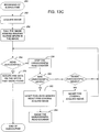
- the routine of FIG. 13A also employs some subroutines, particularly those of FIGS. 13B and 13C.
- the subroutine of FIG. 13C relates to acquiring a digitized image (block 220) which results in the pixel data memory 70 providing a sum of the pixel values (block 222) which is analyzed to determine if it has been successful (block 224) ad if so calculates the average pixel values for the area (block 226) which results in the end of the subroutine (block 228).
- the subroutine steps the unsuccessful read counter (block 230) to attempt to find a area of good pixels, preferably an area of 300 by 300 pixels, and if it is unsuccessful in doing so after nine attempts (block 232), it resets the pixel data memory and strobe control 64 to acquire another digitized image (block 234). When that is done, the unsuccessful read counter is cleared (block 236).
- the routine acquires a digitized image (block 250) and the pixel data memory 70 routine locates the spots in the digitized image (block 252) which if successfully completed (block 254) results in data identifying the spots being forwarded to memory (block 256). If the read was not successful, then the read counter is stepped (block 258) and if there are nine unsuccessful reads (block 260), the pixel data memory 70 is reset as is the strobe control 64 and another image is acquired (block 262). Once this is done, the read counter is cleared (block 264).
- the strobe units 40 are positioned to direct the center of the light to a point 152 which is also the center line for the CCD matrix sensor 30.
- the light passes through the windows 154 to the area of the web and illuminates the web from two directions. Since the intensity of the pixels of an acquired matrix image is a function of the amount of light that is produced by the strobe units, it is important that the area of the acquired matrix image be uniformly illuminated or that the illumination of each area be known so that any variations can be compensated for.
- the apparatus does a analysis of the intensity of the light produced by the two strobe units to determine what the light discontinuity characteristic is and provides compensation for any unevenness in light across the matrix image.
- the apparatus does this by analyzing areas of the total acquired digitized image taken from the white standard, with the areas being preferably about 64 by 64 pixels.
- the apparatus averages the intensity of the pixels within each area and then stores the average value with the address or location of each area so that during compensation, any compensation factor will be applied to the measured intensity values for the pixels that are located within each area.
- the compensation analysis is only required to be performed during initial alignment, and perhaps if optical components are adjusted or changed thereafter.
- the software routine for performing the light discontinuity compensation is illustrated in FIG. 14 begining at block 270.
- the first thing that is done is to clear the temporary storage values (block 272) and then start an image analysis loop which results in the CCD matrix sensor moving to the white standard to acquire a digitized image thereof(block 276) and reset maximum intensity values.
- the routine then starts an area loop 278 where sequential areas of 64 by 64 pixels are analyzed (block 280) and the average intensity value for each area is compared to noise measured and a maximum value is checked for. There are 12 by 7 of such 64 by 64 pixel areas and the light field discontinuity compensation factor is calculated by averaging the intensities in each of the areas approximately 20 times.
- the routine sequences through the entire acquired digitized image and continues to run through the loop until it is done with all of the 64 by 64 areas in the acquired digitized image (block 282). When it is, then the areas are normalized to the maximum and the normalized values are saved in memory (block 284). When all images have been completed (block 286), the average stored images are then stored in permanent memory.
- the red, green and blue channels will each have a light discontinuity compensation factor for each of the 64 by 64 pixel areas within the image.
- the brightest intensity is then set at 1 and all others are then calculated relative to the brightest and are typically values such as 0.97, 0.98, 0.99 or 1.0.
- the accuracy of the reflective density measurements is also influenced by the phenomenon that is referred to herein as light scattering, which means that the reflective density determination can be influenced by the relative location and content of the printed matter adjacent to the color blocks of the color block set 112 that is part of the matrix image that is acquired.
- the region 122 above the line 114 can and probably will contain printed matter, as will the region 122 below the line 120.
- the acquired matrix image 138 shown in FIG. 4 includes approximately seven color blocks that also necessarily includes a portion of the areas 122 of the acquired matrix image.
- each color block set 112 may have printed matter 122 that varies in overall lightness depending upon the content of the printed material in the image, the number of light and dark pixels can vary at each key across the width of the web.
- Light scattering effects are substantially produced by higher reflective values, i.e., higher pixel intensity, located in the field of view. However, within the field of view, such higher intensity pixels have more effect, the closer the pixels are to the pixels being measured. Both of these effects, i.e., the amount of high intensity pixels and their closeness to the pixels being measured, are asymptotic in character.
- the CCD matrix sensor has a focusing lens and a CCD matrix sensor prism which splits the matrix image into red, green and blue channels and depending upon the amount of white that is present in the matrix image that was acquired, a small area such as a color block will produce one reading if it is surrounded by black and another reading if it is surrounded by white. The light scatters when it goes through the lenses and ends up changing the reading of the color block of interest.
- a light scattering compensation must be determined for each of the three channels because the readings that are obtained from each of the red, green and blue channels varies relative to one another, depending on the content of the printed matter of the image being acquired. This is partly due to the fact that the strobe units are very bright in blue light, which makes yellow stand out.
- the strobe units are preferably Xenon strobes which have a predominant blue light component. While the output of the Xenon strobes are relatively constant, they can vary up to plus or minus 5% from one strobe firing to another and for this reason, the photo diodes 172 (FIG.
- the photo diodes integrate the light put out by both strobes. While the intensity of light produced during individual firings of the strobe units can vary as much as 5%, it has been found that the variations are random and are generally about 1%. Such variations do not result in substantial variations in the intensity values produced, i.e., perhaps .75 pixels of intensity.
- print test patterns can be used to model the scattering effect and obtain data that will approximate the light scattering compensation curve such as that shown in FIG. 7.
- the compensation for the light scattering phenomenon may be as much as 4 to 5 within the range of 8 to 240 and is enough that inaccurate readings would result if compensation were not made.
- This data is stored in memory for each color. This produced a series of data that resulted in an asymptotic chart as shown in FIG. 7 which produces intensity compensation factors that may be unity down to approximately 0.9, as the percentage of white pixels to the total pixels ranges from 100% to 0.
- the development of data that defines such a curve needs to be done only once for each color, and the curves are then used for each apparatus that is manufactured. However, it should be understood that the amount of light scattering compensation is done for each print job, and a point on the curve for each color for each key is stored in memory for use in compensating for the light scattering that is measured.
- the apparatus analyzes the acquired digitized image of each channel and counts the total number of white pixels within the total image to determine the percentage of white in the total image.
- the pixels are considered white if they have an intensity value that is greater than half way within the total range.
- the light scattering data is stored in memory and is used to compensate the reflective density data that is measured during a reflective density analysis of each color block at each key during operation. It should be appreciated that the lowest percentage of white pixels possible is 80%, so the area of the curve that is actually used is the left portion of the curve shown in FIG. 7.
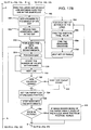
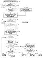
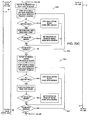
- the routine that is used to acquire light scattering data is illustrated in FIGS. 15A, 15B and 15C, with starting block 300.
- the routine initially calculates the starting and ending locations for the pass of the CCD matrix sensor across the web. The manner in which the apparatus locates the edges of the web and the calculation of the width of the web will be described.
- the apparatus reads the press speed and calculates the speed that is necessary to acquire images of the color block sets at each key location (block 304).
- the apparatus also calculates the acceleration time which is the time required for the carriage 46 to be ramped up to speed starting from a stopped position at a location that is left of the actual web edge 116 shown in FIG. 2.
- the press speed is obtained from the encoder 50.
- the routine sets up the motor speed, the strobe control 64 and pixel data memory 70 and priority is established for this operation (block 308). If the start up time is not acceptable (block 306), then the motor controller 58 changes the location of the carriage 46 so that it will be accelerated and be at the proper path speed by the time it reaches the first key (block 310). If the location is changed, then the press speed is read again, and the path speed and acceleration time recalculated.
- the routine then waits for the next strobe firing opportunity as well as waits for a calculated time using a high speed timer to delay and then starts the motor 52 moving and enables strobe interrupts (block 310).
- the apparatus wants to fire the strobe at a particular encoder count of 2000, for example, and that this time is 8 milliseconds, but depending upon how fast the encoder is rotating, it may or may not require a different number of earlier counts to get the strobe to fire at the appropriate time.
- the apparatus counts up for 1/4 of a revolution using a fixed speed clock and it times how long that takes and determines how many counts it needs to equal 8 milliseconds. When that is determined, it resets the CCD matrix sensor and then down counts and fires the strobe at the 2000 count.
- the apparatus calculates the position and calculates the distance to the closest key (block 312), confirms whether the carriage 46 is up to speed (block 314), which if yes, inquires as to whether the CCD matrix sensor is close to the key (block 316), and inquires whether the press speed has changed (block 318), and if not, it then does the next fire of the strobe and acquires an image (block 312). If the press speed has changed, then the motor speed must be adjusted to match the press speed (block 320). If the CCD matrix sensor is not close to a key (block 316), then the motor speed is recalculated to arrive at the next key on time (block 322).
- the routine inquires as to whether the next key is on the web (block 324), and if not, returns to block 312. If the key is on the web, then the apparatus sets up the pixel data memory 70 and the strobe control 64 and it fires the CCD matrix sensor to acquire two images (block 326) and starts the analysis of the first image.
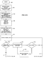
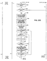
- the routine then starts the main key loop (block 328) and calculates the position and the key number (block 330), determines whether it is close to the key (block 332), inquires if the press speed is changed if it is close to the key (block 334) and recalculates the motor speed to arrive at the next key on time if it is not (block 336). If the press speed has changed, it adjusts the motor speed to match the press speed (block 338) and if it has not, it starts the next acquire of an image (block 340) and analysis.
- the routine determines if the previous key was the last key on the web (block 342) and if not, returns to block 328 to execute the loop until the last key has been acquired and then resets the pixel data memory 70 and the strobe control 64 (block 344).
- the routine then stores the data acquired (block 346) ad starts an analysis loop 348 which includes getting a intensity percentage which is mapped into the light scattering data (FIG. 6) and determines the compensation for each particular key (block 350). This loop is continued until all data has been analyzed (block 352) and the routine inquires whether data was found for all of the keys (block 354) and if has, it averages the past data into prior saved data and counts that particular light scattering pass (block 356). If it is not the final, i.e., the 6th light scattering pass, the routine reverses the path direction (block 358) and restarts the subroutine at block 300 until the sixth light scattering pass is completed which then ends the subroutine.
- an analysis loop 348 which includes getting a intensity percentage which is mapped into the light scattering data (FIG. 6) and determines the compensation for each particular key (block 350). This loop is continued until all data has been analyzed (block 352) and the routine inquires whether data was found for all of the keys (block 354) and
- the apparatus will track the edge of the web during its waiting state so that it can accurately calculate the location of the color block sets, and enable the color block sets to be located when it takes a reflective density pass.
- the edge of the web is determined by acquiring images of a known position in the web and then generally stepping toward the edge and analyzing the pixels to locate the edge, with the analysis relying on the fact that white paper, which is typically what the web is, has an intensity value which is known to be between 240 and approximately 128.
- the roller has no ink on its surface, it generally produces intensity values of the maximum of 255. Therefore, if the intensity is over 240, it is known that the roller surface is being analyzed and if it is between 240 and 128, it is the web itself. If it is below 128, then it is determined to be the printed matter on the web or ink on the roller.
- the apparatus takes advantage of the fact that all printing presses have printing cylinders to which printing plates are attached.
- FIG. 8 which is an end view of a printing cylinder 370
- the printing cylinder 370 has a gap 372 which is used to attach printing plates to the cylinder 370 and the printing plates extend from one side of the gap around the circumference of the cylinder 370 to the other side of the gap where it is attached.
- the importance of the gap is that it is present on every impression cylinder and provides a printing gap on the web because printed matter cannot be printed on the portion of the web that overlies the gap 372.
- the portion of the web that would be present in the area is represented by the area that results from the gap 372 is shown between the lines 376 and 378 as shown in FIG. 9.
- the gaps 372 are becoming smaller in state of the art printing presses, and some presses now have a gap of only 0.040 inches, compared to a full 0.25 inches in many previous presses.
- the printing plates print two pages with the space between the impressions being identified at 124 where the color block sets are printed.
- the state of the art presses are also reducing the gap 124 shown in FIGS. 3 and 4, and may be only 0.100 inches. This requires the height of the blocks to be only 0.09375 inches, which is approximately 112 pixels. The height of the blocks may become even significantly smaller.
- the apparatus locates the edge of the web using routines shown in FIGS. 16A, 16B and 16C as well as FIGS. 17A, 17B and 17C.
- the routine of FIG. 16A it starts at block 380 and switches on a i-mod mode selection (block 382) and sets it to either case 1 or 2 (block 384) and if it is the first time through the routine, it initially sets a i-mod equal to 0 (block 386).
- the routine is started, it is important that the apparatus know where it is and for that reason, the motor is moved to the left-most stop position so that it then can be moved to the correct position for starting the analysis.
- the general scheme of this routine is to locate a color block which then enables it to verify the size of the paper and determine the color block set locations. This is for the purpose of making sure that the apparatus is acquiring images of the color block sets. Once it finds the end color block sets, it uses their existence to check how wide the paper is. If a press run is continuing in a maintain mode, the apparatus is continually scanning by looking for one of the color block sets on the edge of the paper to see if the web is moving either horizontally or circumferentially, i.e., it is tracking the web.
- the routine runs in three modes, i.e., the start up mode where the first time it is run, it is attempting to locate the color block set and determine the width of the paper. Once it has done that successfully, it checks to make sure that the keys on the edge of the web are usable. The reason for this is that sometimes indicia is printed over the top of the color block sets or the end color block set may be half on or half off the web and is not capable of being used. Thus, the routine checks the outermost keys to see if the keys are valid and if the outermost key is not, it moves to the next key and uses that key color block set to track the web.
- the apparatus locates the color block set, determines the width of the paper, and finds valid keys and once that has been accomplished, it merely analyzes the edge key during operation and if it loses the edge key, then it jumps back into a search loop looking for it. If that fails for some reason, the apparatus starts the whole process over by looking for the original color block set.
- the apparatus resets the old width and zeros the motor (block 388) and moves to i-mod equal 1 (block 390).
- This block inquires whether the impressions are off, meaning that there is no printed matter on the web and the web is therefore white. If this is the case, the routine scans the operator edge of the web (block 392) by examining pixels that are acquired in an image at locations such as beginning at location 394 (FIG. 8) using a routine that will be hereinafter described, and determines if the area of interest is at the edge of the web. If it is not, then it requires additional images and analyzes the pixels within those images such as at 396 of FIG.
- the apparatus must switch to the routine that will be described in connection with FIGS. 17A, 17B and 17C.
- the above described portion of the routine is carried out whenever the press starts and it also runs constantly during the maintain mode of the apparatus where a sample is taken approximately every 500 impressions and this routine tracks the edge of the web.
- the apparatus initially searches for a color block set in the center of the web (block 406) and starts the search loop (block 408) which is a subroutine that will be described in connection with the flow chart shown in FIG. 20.
- the routine attempts to initially locate a color block set which cannot be done if the impressions are off, i.e., no printing is occurring. However, if the impressions are on, it attempts to locate the color block set by moving the CCD matrix sensor to the last known location of a color block set and acquires an image. If the color block set is acquired, then it can continue the analysis (block 410).
- the last known location does not produce a color block set, then it searches nine other previously known locations sequentially in an attempt to locate the color block set and if none of those locations reveals a color block set, then it performs a search of the full web to find a color block set (block 412).
- the apparatus moves the CCD matrix sensor to center the color block set (block 414) then inquires whether the i-mod is greater than 1 (block 416). If it is greater than 1, it sets i-mod equal to 4 (block 418) and if not, it inquires whether it is equal to 1 (block 420). If i-mod is not 1, the routine attempts to find the first key (mode 422), then the last key (block 424) and it calculates the number of keys (block 426) and sets i-mod equal to 4 (block 28) which is the running mode of the apparatus. At i-mod equals 4, the end key is monitored as described above.
- the routine finds the end key (block 430) and then moves to case 4 (block 432) where it moves to the first key (block 434) and inquires whether the color block set has been found (block 436) which if yes, ends the routine (block 438). However if it does not find the color block set, the routine is switched to i-mod equals 3 (block 440) where it attempts to find the color block set.
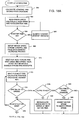
- this flow chart illustrates a routine for finding the edge of the web in the event that the impressions are on, i.e., there is printed matter on the web and none of the color block sets can be located.
- the subroutine shown in FIGS. 17A through 17C operates to locate the edge of the web by locating the gap between lines 376 and 378 (FIG. 9) on the web and then finding the edge of the web using the gap area because it is known that no printed matter will be on the web at this location.
- the routine begins at block 460 and it first determines the starting point for the edge search which is near the center of the web (block 462).
- the main loop is then started (block 464) and the pixel data memory 70 is tested and the FIFO buffers are cleared (block 466).
- the routine acquires a image 468 and it analyzes the acquired image by reading two vertical lines of the acquired image, such as is shown at 470 and 472 of FIG. 9.
- the exercise is to acquire images and analyze vertically until there is concurrence in the analysis from traveling along the lines 470 and 472 until the gap between lines 376 and 378 is reached and confirmation that the images are indeed in the gap.
- the routine can move toward the edge as was described with respect to the points 394 and 396 described previously with respect to FIG. 9.
- two vertical lines are read (block 474) and the search for the gap is started (block 476).
- the routine uses groups of four pixels to find an average pixel value throughout the analysis (block 478). The reason for using four pixels is that some paper webs have a texture which is very rough and can provide distorted readings because of the unevenness of the surface. When four pixels are averaged, there is good assurance that the value will be consistent regardless of the roughness of the paper.
- the summed values are then analyzed to determine if the mean value is within a predetermined range (block 480) and if so, it is then marked as the beginning pixel in the gap (block 482) and the pixel count is then stepped (block 484). If the mean value is not within range, it determines whether there are more than 50 consecutive values previously in the range (block 486) and if not, it clears the pixel count (block 488) and causes the analysis to move down the vertical lines 470 and 472 of FIG. 9 by one pixel (block 490). If there were greater than 50 consecutive values in the range, then the pixel is marked as the end pixel (block 494) and the gap count is then stepped (block 496). After the analysis moves down the lines one pixel, it has reached the end of the gap search loop (block 492) and if it has not located the gap, the gap search loop is again started (block 476).
- the routine makes sure that the gap is found on each of the lines 470 and 472 and also confirms that the gap 112 is in the same place for each of the lines (block 498).
- the routine then sets a pointer in the middle of the gap (block 500) and then analyzes two horizontal lines in the gap (block 502) and for each set of 20 pixels in the lines (block 504) finds the average pixel value (506) as well as the standard deviation (block 508) and then proceeds to the next set of pixels (block 510).
- the routine then indexes to other data arrays (block 526) and returns to block 512.
- the routine determines whether the edge is within the acquired image (block 528) and if it is, analyzes whether there is more of the web shown than that of the roller, it invalidates the edge position. If the edge is not in the image, it inquires as to whether it is an invalid position (block 532). If it is an invalid position, it converts the position to inches (block 534). If it is not an invalid position, it inquires whether it was the first attempt and if the position is on the web (block 536). If it is not on the web, then the routine moves the CCD matrix sensor in (block 538) but if it is, it moves the CCD matrix sensor out (block 540).
- the routine inquires whether it is past the limits (542) and if not, it determines if the edge of the web has been found (block 544). If the CCD matrix sensor is past limits (block 542), it is set to the original search position (block 546). If the edge is found, it then returns the position of the edge of the web (block 546) and the routine is ended (block 548).
- the aforementioned software routines are necessary in setting up the apparatus to acquire the actual reflective density data during operation and accurately determine a reflective density value.
- the routines effectively locate the color blocks of the color block sets for each key and calibrate the digitizing portion of the apparatus, as well as compensate for intensity of the strobe units, discontinuity of the light over the area of the image and compensate for light scattering.
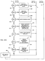
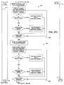
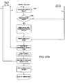
- the routine that is used to acquire reflective density data is illustrated in FIGS. 18A, 18B and 18C which after being started, calculates the starting and ending locations for each pass (block 560), reads the press speed and calculates the pass speed and acceleration time that is required (block 562). If the start up time is okay (block 564), it sets up the motor 52 speed, the strobe control 64, and the pixel data memory 70 and increases the priority of the acquisition of reflective density data so that the operation will not be interrupted (block 566). If the start up time was not okay, then the start-up distance is changed (block 568) in the same manner that has been previously described in connection with FIG. 15A when light scattering data is acquired.
- the apparatus waits for the next strobe firing, waits to use the high speed timer, and starts the motor 52 moving and enables the fire interrupts (block 570).
- the routine then calculates the position and the next closest key (block 572), inquires whether the carriage is moving at the desired speed (block 574) which if yes, then determines if the CCD matrix sensor is close to the key (block 576). If the motor is not up to speed, then the program inquires whether the next key is on the web (block 578) and if not, returns to block 572. If the next key is on the web, then the routine sets up the pixel data memory 70, the strobe control 64 and acquires two images and starts the analysis of the first block (block 580, FIG. 18B).
- the routine determines that the CCD matrix sensor is not close to the key, it recalculates the motor's speed to arrive at the next key at the right time (block 582). If the CCD matrix sensor is close to a key, the routine then inquires as to whether the press speed has changed (block 584) and if it has, it adjusts the motor speed to match the press speed (block 586) and if not, it makes the inquiry (block 578) as to whether the next key is on the web.
- the program starts the main key loop (block 588) and calculates the position it is in as well as the location of the next key (block 590), inquires whether it is close to the key (block 592) and if not, recalculates the motor speed to arrive at the next key on time (block 594), but if it is, it then inquires as to whether the press speed is changed (block 596). If it has, it adjusts the motor speed to match the press speed (block 598), but if it has not, it acquires another image and starts the next analysis (block 600). If the previous analysis results are done (block 602) it stores those results and uses the results to recenter the image (block 604).
- the routine starts the reflective density analysis loop and initially provides the average sum, the number of pixels, the color that is being analyzed, the position on the screen, and the calculated raw average of the reflective density (block 614). It then calculates the compensation for the light discontinuity that is required for the particular pixels of interest as well as the light scattering compensation (block 616) and obtains the white and black levels for the color being analyzed and calculates a compensated average (block 618). It then calculates the reflective density from the compensated average and white and black levels for the color being analyzed (block 620). It calculates the key number and stores the reflective density value under the key number and the color and sets a good reflective density status (block 622).
- the data that is obtained from the reflective density analysis loop is the color that is being analyzed, the x and y coordinate positions on the image, the height and width of the area being analyzed, the sum of all the pixels in the area and the number of pixels that were summed.
- the subroutine that is used to locate the color blocks within the color block set such as shown in FIGS. 3 and 4 is set forth in the flow chart of FIGS. 19A and 19B.
- the subroutine begins at block 640 and the apparatus is set up to acquire an image at the first key location (block 642).
- the image is acquired (block 644) and the color block set search routine hereinafter described with respect to FIG. 27 is invoked to locate all color blocks 130-136 that are present in the image (block 646).
- the routine reads the data for a block (block 650).
- the color blocks are approximately 60 pixels by 112 pixels in size and the analysis area is a rectangle 651 that is preferably located within the center of the color blocks and is preferably of a 40 by 70 pixel size.
- the routine determines if the read is successful (block 652) which if it was, inquires whether there were four or more blocks (block 564) and the average vertical block location is calculated (block 656). It then determines if the block is greater than 50 pixels from the center of the color block (block 658) and if yes, adjusts the vertical position of the CCD matrix sensor (block 660) and resets the read counters (block 662). The apparatus then proceeds to the next block (block 664) which either returns to block 648 or proceeds to block 666 in FIG.
- the routine checks to see if the correct color block is being analyzed (block 668). This is done by verifying the correct order of the blocks, determining that the spacing is reasonable, confirming that every fourth block is the same color and confirming that the black block has a tab. The routine removes blocks that are not properly spaced (block 670). The routine then inquires to determine if the correct color block has been found (block 672) and if not, makes a horizontal adjustment of the CCD matrix sensor (block 674). If yes, the routine returns the number of blocks that were found (block 676).
- the read counter is stepped (block 680) and if there are 20 unsuccessful reads (block 682), the routine times out and reacquires another image (block 684). If there are not 20 unsuccessful reads, the routine inquires there were greater than 40 unsuccessful reads (block 686) and if there were, it also resets and reacquires the image (block 688).
- the subroutine that controls the searching to find a color block set i.e., block 646 of FIG. 19A, is illustrated in FIGS. 20A-20C and starts at block 700.
- the routine of FIGS. 20A-20C therefore controls the movement of the carriage and CCD matrix sensor to locate the color block set if it has been lost.
- the routine inquires whether the position is correct (block 704), and if not, position adjustments are made (block 706) and the CCD matrix sensor is then moved into position and is set up to acquire an image (block 708).
- the vertical position and fire angle is calculated (block 712) and an image is acquired (block 714) after which the color block set search routine is executed (block 716).
- the routine inquires whether there were four or more color blocks located (block 724). If the read was unsuccessful, the attempted read counter is implemented (block 726) and the routine inquires whether there have been 20 unsuccessful reads (block 728) which if there have been, the routine then times out and reacquires a image (block 730) (FIG. 20B). If there have not been 20 unsuccessful reads, then the routine inquires whether there have been more than 40 unsuccessful reads (block 732).
- the routine If there are 40 unsuccessful reads, there is an assumption that the pixel data memory is malfunctioning and the routine totally resets the pixel data memory 70 and reacquires another image (block 734) and if not, proceeds to the next block 736. If there are four or more blocks located (block 724) the routine then calculates the average vertical block location (block 738) and inquires whether it is greater than 50 pixels from the center (block 740). If it is not, then the attempted read counter is reset (block 742). If it is greater than 50 pixels from the center, the program then adjusts the vertical position of the CCD matrix sensor (block 744) and resets the attempted read counter.
- the routine checks to see if it is the correct color block (block 748) and inquires if all of the color block is on the screen (block 750) which if not, adjusts the horizontal position (block 752). The routine then removes blocks that are not properly spaced relative to one another (block 754). If the four or more blocks were not found, the routine inquires whether the color block has been found (block 756) which is also done after improperly spaced blocks have been removed.
- the routine returns the number of blocks that were found (block 758) and if the color block was not found, the routine inquires whether the image was close to the color block set (block 760) and if not, does the next vertical search (block 762) but if yes, makes a fine horizontal adjustment (block 764). For each vertical search, the routine returns to the routine block 710 (FIG. 20A) and if the next horizontal search is done (block 766), the routine returns to block 702 in FIG. 20A. If the color block set was not located within the given search space, the routine is then terminated.
- the routine starts at block 800 (FIG. 21A) and sets up a name in the control system 96, opens a memory area for storing data and attaches to CMP 103 (block 802). The routine then waits for the variable transfer, initializes the main data (block 804), waits for the image status and clears old messages (block 804).
- the system then initializes the motor, moves it to the left-most position and a sensor module scan to make a full traverse of the carriage (block 806) then initializes the pixel data memory 70, obtains white and black calibration data and also performs the light discontinuity data acquisition analysis and sends these variables through the CMP 103 to the processor 96 (block 808).
- the main loop is then started (block 810) which has been described in FIGS. 18A through 18C. If the routine has lost its CMP connection (block 812), it then tries to attach to the CMP again (block 814) and if it is still lost (block 816), it again tries to attach (block 818). If it is still not lost, it returns to the main loop 810. The subloop continues to try to attach until it is successful. If it has not lost its CMP connection, the routine then proceeds to an imaging status switchable loop 820.
- Press conditions determine whether case 1, case 2 or case 3 conditions exist (blocks 822, 824 and 826) and the apparatus continuously loops through this subroutine in a manner whereby each time the routine goes through the main loop, either case 1, case 2 or case 3 will be run.
- the image status will then be stepped. If the image status is greater than 3, then it is set to 1 (block 828).
- case 1 is valid, or is set, the press is running, it is past the balance count (i.e., the count for triggering recalibration), it has been over ten minutes since a calibration has occurred and the apparatus is between passes (block 830).
- the apparatus performs a calibration and light discontinuity analysis (block 832) before ending the switch 828.
- the apparatus runs the get edge routines to locate the edge (block 836) before ending the switch (block 828).
- the apparatus acquires light scattering data or reflective density data and updates the values (block 840).
- the routine inquires whether the press is stopped (block 842) and if yes, determines whether it has been stopped over ten minutes. If it has been, it runs the calibration and light discontinuity routines (block 846).
- the routine then operates to switch on an IOPT loop (block 848) which is a switchable loop that sequences through cases 0 through 7 (blocks 850 through 864). Once it has sequenced through these cases, the routine returns to the start of the main loop (block 810).
- an IOPT loop block 848 which is a switchable loop that sequences through cases 0 through 7 (blocks 850 through 864). Once it has sequenced through these cases, the routine returns to the start of the main loop (block 810).
- Each of the cases 0 through 7 is initiated by the operator during operation of the apparatus. If case 0 is set, the apparatus is set to idle state. If it has been more than 10 minutes, the CCD matrix sensor is recalibrated and the light discontinuity analysis performed (block 865). If case 1 is set, the apparatus sends the mode m1 status and sets up the start up mode (block 866). Case 2 sends a mode m2 command and sets up the run mode (block 868). Case 3 sets up the maintain mode (block 870). Case 4 is a user request to recalibrate the CCD matrix sensor (block 872) as well as perform a light discontinuity analysis or returns the motor to its home or zero position.
- Case 5 enables a view request to be handled and a particular portion of the web is located and an image acquired of that location which can be viewed by the operator.
- Case 6 permits a maintenance request to be handled and light discontinuity analysis to be performed (block 876).
- Case 7 sends a mode mo command and sets up a new job (block 878). If none of the cases are requested, the program ends the switch (block 880) and returns to the start of the main loop (block 810).
- the software subroutine which calibrates the digitizing portion of the apparatus and performs spot analysis during the calibration is shown in the flow chart of FIGS. 22A and 22B and begins at block 900 which results in a pointer being established in the region of interest in the pixel data memory (block 902).
- the routine searches a 100 pixel line and finds maximum and minimum red, green and blue values and calculates the average pixel value in the line (block 904). This is analyzed to determine whether the value is high enough that a white calibration standard is to be performed (block 906) and if so, the pixel value limit for the white standard in each channel is set up (block 908) and if not, the black standard pixel value limit for red, green and blue is established (block 910).
- the routine starts to examine each pixel of a 730 by 450 pixel area (block 912) and determines whether each pixel is under the limit of approximately 120 (block 914). If it is under the limit, then the pixel is added to a segment indicating that a spot is present. If the pixel is a pixel of the white standard, then the routine inquires whether a segment is active (block 918). If it is active, the routine loops through known old spots 920, inquires whether the segment is part of a known spot (block 922) and if yes, enlarges the spot size before ending the spot loop (block 926). The routine inquires whether the segment is part of an old spot (block 928) and if not, it establishes a new spot (block 930).
- a spot send loop is started (block 934) which forwards information relating to the spots to the processor 88.
- the routine sends the location size of the next spot 936 until the send spot loop is ended (block 938).
- the routine then sends the end of the data (block 940) and ends the subroutine (block 942).
- FIGS. 23A through 23E The manner in which the apparatus performs the search for the color blocks and does the reflective density analysis is set forth in FIGS. 23A through 23E which starts at block 1000 and immediately sets a pointer to a region of interest in the pixel data memory and initializes the data to be analyzed (block 1002).
- FIG. 4 which illustrates a single bar, it is analyzed in the manner set forth in the flow chart of FIG. 23A through 23E.
- the routine sets up a vertical search from the center out (block 1004) and may start at a point 1006 in FIG. 4.
- the top of a vertical search loop is shown in block 1008 and the routine sets up a pointer to start a line horizontal search also from the center out such as at point 1006 in FIG. 4 (block 1010).
- the top of the horizontal search loop is indicated in block 1012 and the routine obtains red, green and blue averages for groups of four pixels at the start position (block 1014).
- the routine determines whether any of the three channel's average (red, green and blue) is below the white limit (block 1016) and if so, it determines the color of the average (block 1018).
- the color block found will be one of the three color channels and the channel of the color that is the color of the actual color block being examined will be significantly lower in intensity level than the other two channels. If the block is black, then all three channels will be low and the apparatus uses a single channel for black color blocks.
- each channel receives only one of the colors of red, green and blue, and if the corresponding ink color which takes away from the signal level on the channel is present, then that channel will be low.
- the apparatus takes advantage of that fact by utilizing an exclusive-OR function in each channel, it can determine if that color is present. This is done by setting one input high (1) and if that color is present, a low (0) output from the exclusive-OR will be obtained. If the low output is not produced, then it is known that the particular color is no longer present or being measured.
- the routine inquires whether this color has already been found (block 1020). If not, the routine sets up the various limits for block searches (block 1022) and sets up to search from the point 1005 in FIG. 6 to the left to determine the left edge 144 of the block (block 1024). The routine then steps left 5 pixels to get the RGB averages for the four pixels at that location (block 1026), determines whether they are within limits (block 1028), and if not, steps back within the block and the search of the left edge is completed (block 1030).
- the routine inquires whether the analysis is at the edge of the image (block 1034) and if so, it sets the position to the edge of the image, and the search is completed (block 1036). If not at the edge of the image, then the routine inquires whether the search is completed (block 1038) and if not, it returns to block 1026 to step five pixels further left until the left edge is located.
- the routine searches in the rightward direction to locate the edge 146 of the color block and this is accomplished using the same steps as has been described in blocks 1024 through 1038, with these steps being identified at 1040 in FIG. 23B. Similarly, the routine searches for the top edge 140 shown in FIG. 6 by carrying out the sets identified at 1042 in FIG. 23C followed by a search for the bottom edge 140 which is carried out by the steps identified at 1044 in FIG. 23C. Having identified each of the four boundaries of the color block 136, the routine then calculates the size of the color block (block 1046 in FIG. 23D) and determines whether the block is within desired dimensional limits (block 1048). In other words, the routine determines if a good color block has been identified.
- the routine calculates the center of the block and the size of a search area (block 1050). It calculates the average of the pixels that were found and also upper and lower limits for the color that is being analyzed (block 1052). It then clears the pixel sum and sets up loop counters (block 1054) that will be used in connection with performing the reflective density analysis of the color of the color block.
- the routine then starts a vertical loop (block 1056), a horizontal loop (block 1058) and steps to the next pixel (block 1060), inquires whether it is within limits (block 1062) and if so, adds that pixel value into the sum and counts the pixel (block 1064), which ends the horizontal loop (block 1066) and the vertical loop (block 1068).
- the area that is analyzed from blocks 1056 through 1068 is also shown in FIG. 6 to comprise an area defined by the rectangle 651 that is approximately 40 by 70 pixels in size. If the analysis area 651 has spots such as spots 1072, the pixels in the spots will not be counted into the number of pixels that are counted and their values will not be included. Effectively, the spots are ignored from being averaged. After the total good pixel count has been averaged, the routine determines if the pixel count is greater than 2000 (block 1074).
- the routine sets an error bit 1076 and moves to the edge of the rectangle 1070. It is believed that a pixel count in excess of 2000 is necessary to insure reliable reflective density readings. If the count is greater than 2000, then the analysis is counted (block 1078) and this color is then considered to be found and measured. The results are sent to the FIFO buffer (block 1080).
- the routine then makes a general inquiry as to whether any blocks within the color block sets have been found (block 1082) and if yes, was this the first color block (block 1084). If yes, then move left two color blocks (block 1086) or right one color block if not (block 1088). If no color blocks were found, then the analysis is moved one half color block outwardly (block 1090) and the bottom of the horizontal search loop is reached (block 1092). The routine then steps to the next vertical position (block 1094) and the bottom of the vertical loop is reached (block 1096). The ending color block is then sent to the FIFO buffer (block 1098) and the routine ended (block 1100).
- FIGS. 23A through 23E finds the color blocks by starting from the center and working out rather than working across the screen. If it finds one of each color and analyzes it, the reflective density analysis is carried out.
- Another routine that is very similar to that shown in FIGS. 23A-23E is shown in FIGS. 27A-27D, which operates to locate all color blocks in an image, but does not perform any reflective density analysis.
- the reference numbers of identical steps of the routine shown in FIGS 23A-23E are used in FIGS. 27A-27D, and the final steps shown in FIG. 27D are apparent and do not need additional description.
- the routine of FIGS. 27A-27D is also used by the get edge routine shown in FIGS. 16A through 16C to find the color block set.
- the apparatus also utilizes a number of averaging subroutines which are similar to one another.
- the 300 by 300 pixel averaging routine of FIG. 24 is used in the light discontinuity analysis. Referring to the averaging routine of FIG. 24, it starts at 1110, obtains the pointer through the region of interest in the buffer and clear pixel counters (block 1112), sets up a vertical search from the center out (block 1114) and starts at the top of the vertical search loop (block 1116). The routine sets the pointer to the start of a line and sets the horizontal search loops (block 1118) beginning at the top of the horizontal search loop (block 1120).
- the routine then sums each RGB channel separately and steps the buffer pointer after each pixel is summed (block 1122) and the routine then reaches the bottom of the horizontal search loop (block 1124) as well as the bottom of the vertical search loop (block 1126) and it sends the results back to the FIFO buffer (block 1128) before ending the subroutine (block 1130).
- a routine for averaging any area request is illustrated in FIG. 25 which starts at block 1140 wherein a region of interest as well as horizontal and vertical position and size to be searched is read from the FIFO buffer (block 1142) and the pointer is set to a region of interest in the pixel data memory and the pixel counters cleared (block 1144).
- the routine sets up a vertical search (block 1146), goes to the top of the vertical search loop (block 1148), sets up pointers to start a line and sets up the horizontal search loop (block 1150), goes to the top of that horizontal search loop (block 1152), sums each RGB channel separately and steps the buffer pointer as it does so.
- the routine then reaches the bottom of the horizontal search loop (block 1156) as well as the vertical search loop (block 1158), sends the results back to the FIFO buffer (block 1160) and ends the subroutine (block 1162).
- FIG. 26 is a flow chart that of a subroutine that is used to determine how many pixels are white in the image that is acquired during the light scattering compensation analysis.
- the subroutine starts at (block 1170) and the FIFO buffer is read to obtain the region of interest (block 1172).
- the routine sets the pointer to the region of interest in the pixel data memory (block 1174) and it clears the counters.
- a vertical search is then set up (block 1176) and the routine proceeds to the top of the vertical search loop (block 1178) followed by setting up a pointer to start at a line and set up a horizontal search loop (block 1180) and proceed to the top of the horizontal search loop (block 1182).
- the routine then sets up the pointer to a current pixel and sums each RGB channel if its value is above the limit, preferably 120 in intensity (block 1184).
- the bottom of the horizontal search loop is reached (block 1186) as is the bottom of the vertical search loop (block 1188).
- the routine then calculates the average values and sends the results to the FIFO buffer (block 1190) and the subroutine has ended (block 1192).
- the white level is preferably calibrated to be within the range of 200 to 240 and the black level within the range of 0 to 63, this is for standards that are not perfectly reflective (white) or perfectly nonreflective (black).
- the apparatus reliably produces measurements that are substantially comparable to those produced by an accurately calibrated hand-held densitometer.
- the nozzle 34 is designed to prevent admission of dust and other particles into the center thereof which could obstruct the lens of the CCD matrix sensor 32 and reduce the number of pixels that would be included in the various analyses that have been described above.
- the nozzle 34 has a pair of ports 1200 to which a air hoses 1202 are attached, and the hoses are connected to a source of positive air pressure so that air is admitted to the nozzle 34.
- the nozzle has an internal annular chamber 1204 with an inner wall 1206 which has a number of openings 1208 which direct the air into the center of the nozzle 34.
- the air is directed toward the main central opening and the openings 1208 are slightly angled relative to the center line of the CCD matrix sensor to create a swirling effect. The air stream thereby tends to restrict entrance of particles into the nozzle where they could reach the lens.
- the apparatus can provide reflective density measurements in real time while the press is running at speeds in excess of 3000 feet per minute and can produce control signals that can be used to control the individual keys of a printing press to provide the desired ink reflective density during operation.
Landscapes
- Engineering & Computer Science (AREA)
- Quality & Reliability (AREA)
- Inking, Control Or Cleaning Of Printing Machines (AREA)
- Spectrometry And Color Measurement (AREA)
Applications Claiming Priority (2)
| Application Number | Priority Date | Filing Date | Title |
|---|---|---|---|
| US434244 | 1982-10-14 | ||
| US08/434,244 US6058201A (en) | 1995-05-04 | 1995-05-04 | Dynamic reflective density measuring and control system for a web printing press |
Publications (3)
| Publication Number | Publication Date |
|---|---|
| EP0741032A2 true EP0741032A2 (fr) | 1996-11-06 |
| EP0741032A3 EP0741032A3 (fr) | 1997-06-11 |
| EP0741032B1 EP0741032B1 (fr) | 2001-11-07 |
Family
ID=23723435
Family Applications (1)
| Application Number | Title | Priority Date | Filing Date |
|---|---|---|---|
| EP96106538A Expired - Lifetime EP0741032B1 (fr) | 1995-05-04 | 1996-04-25 | Dispositif de mesure de la densité réflective et système de contrôle pour une machine à imprimer des bandes |
Country Status (3)
| Country | Link |
|---|---|
| US (1) | US6058201A (fr) |
| EP (1) | EP0741032B1 (fr) |
| DE (1) | DE69616644T2 (fr) |
Cited By (4)
| Publication number | Priority date | Publication date | Assignee | Title |
|---|---|---|---|---|
| FR2733721A1 (fr) * | 1995-05-04 | 1996-11-08 | Quad Tech | Systeme et procede de controle des couleurs dans une presse d'imprimerie |
| EP0860276A1 (fr) * | 1997-02-19 | 1998-08-26 | Baldwin Grafotec GmbH | Procédé et dispositif de contrÔle de qualité |
| EP1262323A1 (fr) * | 2001-05-29 | 2002-12-04 | Web Printing Controls Co., Inc. | Système pour surveiller et de controller dynamiquement une machine à imprimer des bandes |
| US6499402B1 (en) | 2000-05-17 | 2002-12-31 | Web Printing Controls Co., Inc. | System for dynamically monitoring and controlling a web printing press |
Families Citing this family (35)
| Publication number | Priority date | Publication date | Assignee | Title |
|---|---|---|---|---|
| JP3384769B2 (ja) * | 1999-04-19 | 2003-03-10 | リョービ株式会社 | インキ供給量調整装置およびインキ供給量調整方法 |
| JP4046465B2 (ja) * | 1999-09-17 | 2008-02-13 | 株式会社リコー | 画像処理装置、画像処理方法、及び画像処理システム |
| DE29916379U1 (de) * | 1999-09-17 | 1999-12-09 | MAN Roland Druckmaschinen AG, 63075 Offenbach | Vorrichtung zum densitometrischen Ausmessen von Druckprodukten |
| DE10049752A1 (de) * | 1999-10-11 | 2001-05-10 | Heidelberger Druckmasch Ag | Verfahren zur Erkennung der Lagegenauigkeit von Register und Falz-oder Schneidkanten an flachen Exemplaren |
| JP2003154629A (ja) * | 2001-11-22 | 2003-05-27 | Ryobi Ltd | 両面印刷機の印刷濃度管理装置 |
| US20030147090A1 (en) * | 2002-02-06 | 2003-08-07 | Quad/Tech, Inc. | Camera assembly for a printing press |
| US7253929B2 (en) * | 2002-02-06 | 2007-08-07 | Quad/Tech, Inc. | Camera assembly for a printing press |
| US7245315B2 (en) * | 2002-05-20 | 2007-07-17 | Simmonds Precision Products, Inc. | Distinguishing between fire and non-fire conditions using cameras |
| US7256818B2 (en) * | 2002-05-20 | 2007-08-14 | Simmonds Precision Products, Inc. | Detecting fire using cameras |
| US7280696B2 (en) * | 2002-05-20 | 2007-10-09 | Simmonds Precision Products, Inc. | Video detection/verification system |
| US7187472B2 (en) | 2002-09-03 | 2007-03-06 | Innolutions, Inc. | Active color control for a printing press |
| US7228004B2 (en) * | 2002-09-05 | 2007-06-05 | Eastman Kodak Company | Method for sharpening a digital image |
| US7627141B2 (en) | 2003-04-25 | 2009-12-01 | Quad/Tech, Inc. | System and method for measuring color on a printing press |
| US20040213436A1 (en) * | 2003-04-25 | 2004-10-28 | Quad/Tech, Inc. | System and method for measuring color on a printing press |
| US8441700B2 (en) * | 2003-04-25 | 2013-05-14 | Quad/Tech, Inc. | Image processing of a portion of multiple patches of a colorbar |
| DE102004003615B4 (de) | 2004-01-25 | 2005-12-15 | Man Roland Druckmaschinen Ag | Vorrichtung und Verfahren zur Erfassung und Auswertung eines Bildes von einem vorbestimmten Ausschnitt eines Druckerzeugnisses |
| DE102004003612B4 (de) | 2004-01-25 | 2015-01-08 | grapho metronic Meß- und Regeltechnik GmbH | Verfahren und Auswertung eines Bildes von einem vorbestimmten Ausschnitt eines Druckerzeugnisses |
| JP4969025B2 (ja) * | 2004-01-30 | 2012-07-04 | 三菱重工業株式会社 | 燃料電池用膜電極および燃料電池 |
| US7489425B2 (en) * | 2004-03-15 | 2009-02-10 | Heidelberger Druckmaschinen Ag | Method for controlling an operating process of a printing machine |
| US20050226466A1 (en) * | 2004-04-06 | 2005-10-13 | Quad/Tech, Inc. | Image acquisition assembly |
| US20070013904A1 (en) * | 2005-07-15 | 2007-01-18 | Chia Chee W | Apparatus and system for characterizing a target |
| US7477420B2 (en) * | 2005-09-07 | 2009-01-13 | Innolutions, Inc. | Barless closed loop color control |
| US7859668B2 (en) | 2005-12-15 | 2010-12-28 | Honeywell International Inc. | Apparatus and method for illuminator-independent color measurements |
| US8017927B2 (en) * | 2005-12-16 | 2011-09-13 | Honeywell International Inc. | Apparatus, system, and method for print quality measurements using multiple adjustable sensors |
| US7688447B2 (en) | 2005-12-29 | 2010-03-30 | Honeywell International Inc. | Color sensor |
| US7573575B2 (en) | 2005-12-29 | 2009-08-11 | Honeywell International Inc. | System and method for color measurements or other spectral measurements of a material |
| US7592608B2 (en) * | 2008-01-22 | 2009-09-22 | Honeywell International Inc. | Apparatus and method for measuring and/or controlling ultraviolet-activated materials in a paper-making process |
| US8049892B2 (en) * | 2008-01-22 | 2011-11-01 | Honeywell International Inc. | Apparatus and method for camera-based color measurements |
| US8291001B2 (en) * | 2008-02-27 | 2012-10-16 | Eastman Kodak Company | Signal processing for media type identification |
| US8132887B2 (en) | 2010-03-02 | 2012-03-13 | Innolutions, Inc. | Universal closed loop color control |
| US8401809B2 (en) | 2010-07-12 | 2013-03-19 | Honeywell International Inc. | System and method for adjusting an on-line appearance sensor system |
| US9628755B2 (en) * | 2010-10-14 | 2017-04-18 | Microsoft Technology Licensing, Llc | Automatically tracking user movement in a video chat application |
| US8666188B2 (en) * | 2011-03-23 | 2014-03-04 | Xerox Corporation | Identifying edges of web media using textural contrast between web media and backer roll |
| JP6630228B2 (ja) * | 2016-05-11 | 2020-01-15 | 株式会社沖データ | 画像形成装置 |
| CN118927794B (zh) * | 2024-09-13 | 2025-03-14 | 惠州市天健彩色印刷有限公司 | 一种纸质包装的印刷控制方法及系统 |
Family Cites Families (23)
| Publication number | Priority date | Publication date | Assignee | Title |
|---|---|---|---|---|
| US4003660A (en) * | 1975-12-03 | 1977-01-18 | Hunter Associates Laboratory, Inc. | Sensing head assembly for multi-color printing press on-line densitometer |
| DE3220298A1 (de) * | 1981-06-01 | 1982-12-16 | Canon K.K., Tokyo | Farbbild-lesegeraet |
| DE3127381A1 (de) * | 1981-07-10 | 1983-01-27 | Salvat Editores, S.A., Barcelona | Messorgane fuer im geschlossenen kreis arbeitende systeme zur ueberwachung und korrektur des drucks bei offset-druckmaschinen |
| JPS58201011A (ja) * | 1982-05-19 | 1983-11-22 | Komori Printing Mach Co Ltd | 絵柄信号の判別方法 |
| DE3219743C2 (de) * | 1982-05-26 | 1985-01-10 | Heidelberger Druckmaschinen Ag, 6900 Heidelberg | Verfahren zur farbmetrischen Auswertung eines auf der Schöndruck- und auf der Widerdruckseite in einem Maschinendurchgang bedruckten Bogens |
| JPS59138903A (ja) * | 1983-01-31 | 1984-08-09 | Komori Printing Mach Co Ltd | 絵柄面積の測定方法 |
| US4668978A (en) * | 1983-08-24 | 1987-05-26 | Kabushiki Kaisha Toshiba | Thermal transfer color image forming apparatus with image color and image color density control functions |
| US4602160A (en) * | 1983-09-28 | 1986-07-22 | Sentrol Systems Ltd. | Infrared constituent analyzer and control system |
| DE3687074D1 (de) * | 1985-03-21 | 1992-12-17 | Felix Brunner | Verfahren, regelvorrichtung und hilfsmittel zur erzielung eines gleichfoermigen druckresultats an einer autotypisch arbeitenden mehrfarbenoffsetdruckmaschine. |
| US5182721A (en) * | 1985-12-10 | 1993-01-26 | Heidelberger Druckmaschinen Aktiengesellschaft | Process and apparatus for controlling the inking process in a printing machine |
| US4794453A (en) * | 1986-09-09 | 1988-12-27 | Web Printing Controls Co. | Method and apparatus for stroboscopic video inspection of an asynchronous event |
| US4845374A (en) * | 1987-07-20 | 1989-07-04 | R. J. Reynolds Tobacco Company | Method and apparatus for detecting the deposition of an adhesive on a travelling web |
| FI78025C (fi) * | 1987-08-31 | 1989-06-12 | Valtion Teknillinen | Foerfarande foer kvalitetskontroll av tryckning. |
| US4993405A (en) * | 1989-05-15 | 1991-02-19 | Olympus Optical Co., Ltd. | Imaging apparatus |
| US5025676A (en) * | 1989-07-03 | 1991-06-25 | Perretta Graphics Corporation | Screw adjustment mechanism with pre-set backlash |
| US5216521A (en) * | 1990-01-10 | 1993-06-01 | Agfa-Gevaert Aktiengesellschaft | Reproduction of photographic originals with scattered light correction |
| US5063845A (en) * | 1990-02-16 | 1991-11-12 | Perretta Graphics Corporation | Anti-wrap for high speed printing press |
| US5155005A (en) * | 1990-03-29 | 1992-10-13 | Fuji Photo Film Co., Ltd. | Method of producing polychromatic colored image |
| US5043904A (en) * | 1990-04-27 | 1991-08-27 | Web Printing Controls Co., Inc. | Web handling apparatus monitoring system with user defined outputs |
| US5182652A (en) * | 1991-09-06 | 1993-01-26 | Eastman Kodak Company | High resolution thermal printing by imaging a hard copy image in vertical and horizontal increments smaller than the pixel pitch of a video imager array |
| US5517575A (en) * | 1991-10-04 | 1996-05-14 | Ladewski; Theodore B. | Methods of correcting optically generated errors in an electro-optical gauging system |
| US5412577A (en) * | 1992-10-28 | 1995-05-02 | Quad/Tech International | Color registration system for a printing press |
| DE4321177A1 (de) * | 1993-06-25 | 1995-01-05 | Heidelberger Druckmasch Ag | Vorrichtung zur parallelen Bildinspektion und Farbregelung an einem Druckprodukt |
-
1995
- 1995-05-04 US US08/434,244 patent/US6058201A/en not_active Expired - Fee Related
-
1996
- 1996-04-25 DE DE69616644T patent/DE69616644T2/de not_active Expired - Fee Related
- 1996-04-25 EP EP96106538A patent/EP0741032B1/fr not_active Expired - Lifetime
Cited By (5)
| Publication number | Priority date | Publication date | Assignee | Title |
|---|---|---|---|---|
| FR2733721A1 (fr) * | 1995-05-04 | 1996-11-08 | Quad Tech | Systeme et procede de controle des couleurs dans une presse d'imprimerie |
| EP0860276A1 (fr) * | 1997-02-19 | 1998-08-26 | Baldwin Grafotec GmbH | Procédé et dispositif de contrÔle de qualité |
| CN1089687C (zh) * | 1997-02-19 | 2002-08-28 | 鲍德温格拉弗泰克有限公司 | 实行质量管理的设备和方法 |
| US6499402B1 (en) | 2000-05-17 | 2002-12-31 | Web Printing Controls Co., Inc. | System for dynamically monitoring and controlling a web printing press |
| EP1262323A1 (fr) * | 2001-05-29 | 2002-12-04 | Web Printing Controls Co., Inc. | Système pour surveiller et de controller dynamiquement une machine à imprimer des bandes |
Also Published As
| Publication number | Publication date |
|---|---|
| DE69616644D1 (de) | 2001-12-13 |
| US6058201A (en) | 2000-05-02 |
| EP0741032A3 (fr) | 1997-06-11 |
| EP0741032B1 (fr) | 2001-11-07 |
| DE69616644T2 (de) | 2002-08-14 |
Similar Documents
| Publication | Publication Date | Title |
|---|---|---|
| EP0741032B1 (fr) | Dispositif de mesure de la densité réflective et système de contrôle pour une machine à imprimer des bandes | |
| US6499402B1 (en) | System for dynamically monitoring and controlling a web printing press | |
| US7187472B2 (en) | Active color control for a printing press | |
| JP3288628B2 (ja) | 印刷機の湿し液を調節するためのシステム及び方法 | |
| US5774225A (en) | System and method for color measurement and control on-press during printing | |
| US4975862A (en) | Process and apparatus for the ink control of a printing machine | |
| JP5715229B2 (ja) | 異なる動作をする2つの測定装置を備えている、色に関する測定を行う装置 | |
| US8132887B2 (en) | Universal closed loop color control | |
| EP1457335B1 (fr) | Dispositif de commande pour une machine à imprimer. | |
| US7477420B2 (en) | Barless closed loop color control | |
| US6178254B1 (en) | Method for elimination of effects of imperfections on color measurements | |
| EP0787283B1 (fr) | Procede de calibrage couleur pendant l'impression avec fonction de verification | |
| US7000544B2 (en) | Measurement and regulation of inking in web printing | |
| US6192801B1 (en) | Measurement field group for detecting quality data in multicolor printing of single editions | |
| CA2497174A1 (fr) | Procede et appareil pour le controle en ligne de la qualite d'impression | |
| EP1262323B1 (fr) | Système pour surveiller et de controller dynamiquement une machine à imprimer des bandes | |
| US5724143A (en) | Method and device for determining the area coverage of an original | |
| EP1629978A2 (fr) | Procédé et appareil de contrôle de la teint de couleurs d'images | |
| JPH02167438A (ja) | オフセット印刷機における多色刷り原稿の測定セグメント内の基本色の表面塗りを判定する方法と装置 | |
| JP3877181B2 (ja) | 巻帯体印刷機用のダイナミック反射密度測定及び制御システム | |
| JP2000356552A (ja) | 印刷面の色彩・濃度測定方法および装置 | |
| JPS637603B2 (fr) | ||
| AU615020B2 (en) | Process and apparatus for the ink control of a printing machine | |
| DE69616644T9 (de) | Dynamische reflektionsdichtemessung und regelsystem fuer eine rollenrotationsdruckmaschine | |
| JPH062408B2 (ja) | 平台校正印刷機 |
Legal Events
| Date | Code | Title | Description |
|---|---|---|---|
| PUAI | Public reference made under article 153(3) epc to a published international application that has entered the european phase |
Free format text: ORIGINAL CODE: 0009012 |
|
| AK | Designated contracting states |
Kind code of ref document: A2 Designated state(s): DE FI FR GB IT |
|
| PUAL | Search report despatched |
Free format text: ORIGINAL CODE: 0009013 |
|
| AK | Designated contracting states |
Kind code of ref document: A3 Designated state(s): DE FI FR GB IT |
|
| 17P | Request for examination filed |
Effective date: 19971118 |
|
| GRAG | Despatch of communication of intention to grant |
Free format text: ORIGINAL CODE: EPIDOS AGRA |
|
| 17Q | First examination report despatched |
Effective date: 20001214 |
|
| GRAG | Despatch of communication of intention to grant |
Free format text: ORIGINAL CODE: EPIDOS AGRA |
|
| GRAH | Despatch of communication of intention to grant a patent |
Free format text: ORIGINAL CODE: EPIDOS IGRA |
|
| GRAH | Despatch of communication of intention to grant a patent |
Free format text: ORIGINAL CODE: EPIDOS IGRA |
|
| GRAA | (expected) grant |
Free format text: ORIGINAL CODE: 0009210 |
|
| AK | Designated contracting states |
Kind code of ref document: B1 Designated state(s): DE FI FR GB IT |
|
| PG25 | Lapsed in a contracting state [announced via postgrant information from national office to epo] |
Ref country code: FI Free format text: LAPSE BECAUSE OF FAILURE TO SUBMIT A TRANSLATION OF THE DESCRIPTION OR TO PAY THE FEE WITHIN THE PRESCRIBED TIME-LIMIT Effective date: 20011107 |
|
| REF | Corresponds to: |
Ref document number: 69616644 Country of ref document: DE Date of ref document: 20011213 |
|
| REG | Reference to a national code |
Ref country code: GB Ref legal event code: IF02 |
|
| PLBE | No opposition filed within time limit |
Free format text: ORIGINAL CODE: 0009261 |
|
| STAA | Information on the status of an ep patent application or granted ep patent |
Free format text: STATUS: NO OPPOSITION FILED WITHIN TIME LIMIT |
|
| 26N | No opposition filed | ||
| PGFP | Annual fee paid to national office [announced via postgrant information from national office to epo] |
Ref country code: IT Payment date: 20090528 Year of fee payment: 14 Ref country code: FR Payment date: 20090518 Year of fee payment: 14 Ref country code: DE Payment date: 20090528 Year of fee payment: 14 |
|
| PGFP | Annual fee paid to national office [announced via postgrant information from national office to epo] |
Ref country code: GB Payment date: 20090528 Year of fee payment: 14 |
|
| GBPC | Gb: european patent ceased through non-payment of renewal fee |
Effective date: 20100425 |
|
| REG | Reference to a national code |
Ref country code: FR Ref legal event code: ST Effective date: 20101230 |
|
| PG25 | Lapsed in a contracting state [announced via postgrant information from national office to epo] |
Ref country code: DE Free format text: LAPSE BECAUSE OF NON-PAYMENT OF DUE FEES Effective date: 20101103 |
|
| PG25 | Lapsed in a contracting state [announced via postgrant information from national office to epo] |
Ref country code: GB Free format text: LAPSE BECAUSE OF NON-PAYMENT OF DUE FEES Effective date: 20100425 Ref country code: IT Free format text: LAPSE BECAUSE OF NON-PAYMENT OF DUE FEES Effective date: 20100425 |
|
| PG25 | Lapsed in a contracting state [announced via postgrant information from national office to epo] |
Ref country code: FR Free format text: LAPSE BECAUSE OF NON-PAYMENT OF DUE FEES Effective date: 20100430 |