EP0741103A2 - Dispositif pour transférer le début d'une bande de matériau dans une rotative - Google Patents
Dispositif pour transférer le début d'une bande de matériau dans une rotative Download PDFInfo
- Publication number
- EP0741103A2 EP0741103A2 EP96810252A EP96810252A EP0741103A2 EP 0741103 A2 EP0741103 A2 EP 0741103A2 EP 96810252 A EP96810252 A EP 96810252A EP 96810252 A EP96810252 A EP 96810252A EP 0741103 A2 EP0741103 A2 EP 0741103A2
- Authority
- EP
- European Patent Office
- Prior art keywords
- web
- deflection
- transfer belt
- roller
- belt
- Prior art date
- Legal status (The legal status is an assumption and is not a legal conclusion. Google has not performed a legal analysis and makes no representation as to the accuracy of the status listed.)
- Granted
Links
Images



Classifications
-
- B—PERFORMING OPERATIONS; TRANSPORTING
- B65—CONVEYING; PACKING; STORING; HANDLING THIN OR FILAMENTARY MATERIAL
- B65H—HANDLING THIN OR FILAMENTARY MATERIAL, e.g. SHEETS, WEBS, CABLES
- B65H39/00—Associating, collating, or gathering articles or webs
- B65H39/16—Associating two or more webs
-
- B—PERFORMING OPERATIONS; TRANSPORTING
- B65—CONVEYING; PACKING; STORING; HANDLING THIN OR FILAMENTARY MATERIAL
- B65H—HANDLING THIN OR FILAMENTARY MATERIAL, e.g. SHEETS, WEBS, CABLES
- B65H45/00—Folding thin material
- B65H45/12—Folding articles or webs with application of pressure to define or form crease lines
Definitions
- the present invention relates to a device for transferring a start of a web of a material web conveyed in a web-fed rotary machine according to the preamble of claim 1.
- the invention also relates to a method for merging two webs of material in a web-fed rotary machine according to the preamble of claim 11.
- the invention is preferably found in a printing press Use.
- substrate webs after the longitudinal folding which is usually carried out by conveying the webs through funnels, are to be brought together again before they are fed to a folder.
- the beginning of the web of the individual partial webs are brought together to form a single web strand, in which the longitudinally folded printing material webs lie approximately one above the other, via corresponding transfer devices.
- the partial webs are brought together or the partial webs are drawn in via the deflection means provided for this purpose in the area of the transfer, in particular deflection rollers, usually by hand.
- An operator takes over a web start of such a longitudinally folded partial web, for example by means of a hook, and hands over the recorded web start to a second operator who gives up or threads the taken web start in the area of a feeding means, in particular a web diverter roller, in such a way that this web start comes to cover with another part web endlessly conveyed in the area of the feed means and is further promoted together with this other part web.
- a feeding means in particular a web diverter roller
- the invention has set itself the task of enabling the transfer of a web start of a web of material conveyed in a roll-type rotary machine without an operator having to pick up such a web start and give it up for further conveyance.
- Claim 10 relates to a particularly preferred use of the invention.
- the conveyed beginning of the web can be deflected in a desired new conveying direction by the guide means around the deflecting means.
- the web start deflected in this way is taken over by a transfer belt and conveyed to a feeding means.
- the beginning of the web of the deflected web lies simply on the transfer belt.
- the transferred web start is appropriately promoted from the area of the feed means.
- the transfer belt is preferably also driven by it against the web conveying means, preferably the deflecting means. In a likewise preferred embodiment, it is driven by its own motor.
- the deflection means is a deflection roller, in particular a register roller
- the feed means is a web deflection roller arranged at a distance from it.
- the printing material web transferred according to the invention runs under a further previously longitudinally folded printing material web, namely the web with which it is to be brought together for subsequent capping and folding.
- a web-fed rotary printing press can have a plurality of transfer devices designed according to the invention, which are usually arranged next to one another transversely to the web conveying direction.
- the deflecting means and the guiding means form a kind of inlet funnel for the start of the web of the material web to be transferred.
- the web start in question becomes essentially vertically downwards from the former to a deflection roller conveyed and conveyed by approximately 90 ° from its conveying direction into a further deflecting roller arranged laterally next to this deflecting roller. Because of this web conveyance, which is supported by gravity, an inlet funnel that is open at the top is completely sufficient for safely diverting the freely hanging web start.
- the transfer belt also forms the diversion means. In order to divert a beginning of the web, this transfer belt partially wraps around the deflecting means.
- the transfer belt is advantageously guided around at least three belt deflection rollers which are arranged in a triangular manner with respect to one another.
- the transfer belt is preferably pressed or set against the deflecting means in the region of a run, in particular an upper run.
- the transfer belt is preferably arranged so that it can pivot against the deflecting means. Since the transfer belt can be adjusted with a partial looping of the deflecting means onto the deflecting means, it can accordingly be switched off again by the deflecting means after transferring the start of the web and further conveying the transferred material web, so that the transferred material web can only be conveyed further via the otherwise customary deflecting means . By switching off after the transfer has been carried out, it is very easily prevented that printing ink which may have been colored on the transfer belt can be transferred to the material web, if it is a printing material web.
- One of the three belt diversion rollers can be formed by the feed means itself. This also represents a preferred embodiment of the invention. According to another preferred embodiment, the transfer belt is mechanically independent of the other deflecting means of the roller rotary machine. Depending on the embodiment, either the feed means designed as a deflection roller or a separate one arranged in the immediate vicinity of the feed means forms Belt deflection roller drives the rotating transfer belt.
- this belt deflection roller is arranged between this belt deflection roller and the feed means to support the start of the web as it enters or runs into or onto the feed means.
- this diversion roller is advantageously provided with circumferential grooves for this purpose, and the web support means engages in these grooves in a rake, so that a seamless task of the web start can be ensured.
- FIG. 1 shows the merging of two partial substrate webs B 1 and B 2 , each of which has been longitudinally folded in funnels T 1 and T 2 .
- the two longitudinally folded substrate sub-webs B 1 and B 2 are each conveyed via pairs of pull rollers 15, the beginning of the web of each of these two sub-webs B 1 and B 2 being initially conveyed freely suspended approximately vertically downward by the respective pair of draw rollers 15.
- a feed means Disposed below one of the two pairs of pull rollers 15 is a feed means, in the exemplary embodiment a web diverting roller 17, at which the free beginning of the web of the corresponding first printing substrate web B 1 is conveyed past at a short distance during its further conveyance by the pair of pull rollers 15 arrives at a further pair of pull rollers 18, runs in between the two rollers of this pair of pull rollers 18 and is conveyed on by them.
- the beginning of the web of the other, second substrate sub-web B 2 must first be brought together with the first substrate sub-web B 1 by a deflection means 16 arranged approximately vertically below the pair of drawing rollers 15 used to convey the second substrate sub-web B 2 , in the exemplary embodiment also a web deflection roller, in particular one Register roller, are deflected and conveyed to the feed means 17 in order to be deflected by the feed means 17 in the same direction as the first printing substrate web B, which is conveyed in a substantially simple manner.
- this beginning of the web is steered around the deflection means 16 by means of a transfer device 2 and conveyed to the feeding means 17 lying on the transfer belt 3.
- the beginning of the web of the second sub-web B 2 is deflected in the conveying direction of the first sub-web B 1 via the feed means 17 and, during its further conveyance, it hangs freely between the rollers of the pair of pulling rollers 18 arranged downstream of the feed means 17.
- the pair of sub-webs B 1 and B 2 is conveyed to a folder 22 in a known manner via a retaining device 19, a cutting device 20 and a further pair of pull rollers 21.
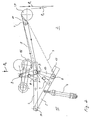
- Figure 2 shows the web transfer device 2 of Figure 1 alone.
- the vertically downward conveyed beginning of the web of the second partial web B 2 to be transferred is indicated before it enters the transfer device 2.
- the deflecting means 16 is formed by a register roller, which is shown in FIG. 2 in its two end positions.
- the transfer belt 3 runs around three belt guide rollers 7, 8 and 9 and one Tensioner roller, which is held on an adjustable arm 4 to.
- the first belt diverting roller 7 is arranged in the immediate vicinity of the feed means 17 formed in the exemplary embodiment by a web diverting roller.
- the three belt guide rollers 7, 8 and 9 form a triangular arrangement.
- the transfer belt 3 In the area of an upper run of the transfer belt 3 between the rollers 7 and 8, the transfer belt 3 is positioned against the register roller 16, so that it essentially registers this register roller 16 from below in the area in which the transferred first web section B 1 wraps around the register roller 16. also wraps around.
- the register roller 16 and the upper run of the transfer belt 3 in the deflection area form a kind of feed hopper for the web start of the partial web B 2, which is conveyed from above.
- the conveyed start of the web initially runs onto the upper run of the transfer belt 3. It is then drawn in between the register roller 16 and this upper run and is clamped around the register roller 16 between the two.
- the beginning of the web lies freely on the upper run in its section between the register roller 16 and the first belt deflection roller 7.
- the beginning of the web, lying on the transfer belt 3 reaches the first belt diversion roller 7.
- a rake-shaped web support means 11 is arranged, by means of which the beginning of the web is conveyed almost continuously onto the downstream web guide roller 17. With its rake-shaped fingers, the web support means 11 engages in the corresponding circumferential grooves of the web guide roller 17.
- the web support means is rotatably mounted on the axis of rotation of the belt deflection roller 7.
- the transfer belt 3 can be set against the register roller 16 or can be set off by pivoting it away. The turning on and off takes place by pivoting about the axis of rotation of the driven belt deflection roller 7. In FIG. 2 this is Transfer belt 3 shown in a solid line in line with the register roller 16 and in a dashed line in its parked position.
- the transfer belt By moving against the register roller 16, the transfer belt is driven by the register roller 16.
- the belt deflection roller 7 is driven by its own motor.
- the second belt deflection roller 8 and the third belt deflection roller 9 are fastened to or from the register roller 16 on an adjusting device 15, which is arranged pivotably about an axis 14, for the purpose of starting and stopping the transfer belt 3.
- the adjusting device 5 is formed by a simple bar 5, which has a stop 13 for limiting the pivoting movement of the adjusting device 15 against the register roller 16.
- the second belt deflection roller 8 is rotatably attached directly to the beam 5, while the third belt deflection roller 9 is rotatably held on a support arm 12 projecting at an angle from this beam 5.
- the arm 4 carrying the tensioning roller for the transfer belt 3 is pivotably attached to the bar 5 for setting the desired belt tension.
- the pivoting movement of the adjusting device 5 about the axis of rotation 14 and thus also the pivoting movement of the transfer belt 3 about the first belt diversion roller 7 is brought about by an actuating cylinder 6 which is articulated on the beam 5.
- the transfer belt 3, seen in the longitudinal direction of the register roller 16, is formed by a plurality of belt strips running parallel to one another.
- the belt guide rollers 7, 8, 9 and the adjusting device 15 are designed accordingly.
- the transfer belt 3 In the parked position, the transfer belt 3 is guided approximately triangularly around the three belt guide rollers 7, 8 and 9. In line with the register roller 16, the belt 3 is in the area of the upper run between the first belt guide roller 7 and the third belt deflection roller 9 are pressed in and thus partially wraps around the register roller 16.
- the transfer belt 3 takes approximately the shape of a lying "L”.
- the short, upward-pointing leg of this "L” forms, together with the register roller 16, the inlet for the partial web B 2 and the wrap around the register roller 16, and the long, approximately horizontal or slightly inclined leg of this "L” points in straight line to the web diversion roller 17 serving as the feeding means.
- Figure 3 shows a first alternative embodiment for a transfer device according to the invention.
- the transfer device according to FIG. 3 differs from that according to FIG. 2 only in that no separate drive roller, namely the belt deflection roller 7, is provided.
- the transfer belt 3 runs around the web diversion roller 17, which thus simultaneously assumes the function of a driven belt diversion roller.
- the transfer belt 3 is accordingly on the axis of rotation of the web guide roller 17 to register roller 16 on and off. Otherwise, the construction and the mode of operation of this embodiment alternative to that according to FIG. 2 are the same.
- a mechanically particularly simple transfer device 2 is shown in FIG.
- a rigid guide means 5, in the exemplary embodiment a simple deflection plate, is arranged adjacent to the register roller 16.
- the guide means 5 in turn forms, together with the register roller 16, a funnel-shaped inlet for the conveyed start of the second partial web B 2 .
- the conveyed start of the web initially encounters a rounded deflecting surface of the deflecting means 5 facing the register roller 16 and slides on this deflecting surface during its further conveyance onto the transfer belt 3.
- An upper end of the guide means 5 is inclined to the incoming web start.
- the deflecting surface of the guide means runs approximately concentrically to the surface of the register roller 16.
- a lower end of the guide means 5 projects in a rake-like manner between the belt strips of the transfer belt 3, so that the beginning of the web is constantly supported from below.
- the transfer of the start of the web on the transfer belt 3 to the downstream web diverter roller 17 is carried out as in the exemplary embodiment according to FIG. 3.
- the transfer belt according to Figure 4 is not pivotable. It only runs around the two stationary belt deflection rollers 17 and 8 and around the tensioning roller 4. This embodiment variant is characterized by its simplicity and its comparatively low acquisition costs.
Landscapes
- Separation, Sorting, Adjustment, Or Bending Of Sheets To Be Conveyed (AREA)
- Advancing Webs (AREA)
Applications Claiming Priority (2)
| Application Number | Priority Date | Filing Date | Title |
|---|---|---|---|
| DE19516655A DE19516655C2 (de) | 1995-05-05 | 1995-05-05 | Vorrichtung zum Zusammenführen von zwei in einer Rollenrotationsdruckmaschine geförderten Materialbahnen |
| DE19516655 | 1995-05-05 |
Publications (3)
| Publication Number | Publication Date |
|---|---|
| EP0741103A2 true EP0741103A2 (fr) | 1996-11-06 |
| EP0741103A3 EP0741103A3 (fr) | 1997-10-15 |
| EP0741103B1 EP0741103B1 (fr) | 1999-09-22 |
Family
ID=7761247
Family Applications (1)
| Application Number | Title | Priority Date | Filing Date |
|---|---|---|---|
| EP96810252A Expired - Lifetime EP0741103B1 (fr) | 1995-05-05 | 1996-04-19 | Dispositif et procédé pour réunir deux bandes dans une rotative |
Country Status (4)
| Country | Link |
|---|---|
| US (1) | US5695180A (fr) |
| EP (1) | EP0741103B1 (fr) |
| DE (2) | DE19516655C2 (fr) |
| ES (1) | ES2139323T3 (fr) |
Families Citing this family (2)
| Publication number | Priority date | Publication date | Assignee | Title |
|---|---|---|---|---|
| US6095047A (en) * | 1998-07-13 | 2000-08-01 | Heidelberger Drukmaschinen Ag | Web-fed rotary printing press with apparatus for diverting a wet printed web |
| DE19941426A1 (de) * | 1999-08-30 | 2001-03-01 | Voith Paper Patent Gmbh | Vorrichtung und Verfahren zum Überführen eines Materialbahnstreifens |
Family Cites Families (13)
| Publication number | Priority date | Publication date | Assignee | Title |
|---|---|---|---|---|
| US852429A (en) * | 1905-06-02 | 1907-05-07 | Shelby Printing Company | Press. |
| DE1229107B (de) * | 1965-04-17 | 1966-11-24 | Leipzig Veb Druckmasch Werke | Vorrichtung zum Einfuehren der Materialbahn in Rotationsdruckmaschinen |
| US3556509A (en) * | 1968-08-21 | 1971-01-19 | Harris Intertype Corp | Printed web ribbon registration control system |
| SE7504029L (sv) * | 1975-04-08 | 1976-10-09 | Wifag Maschf | Falsapparat med sasom kasett utbytbar falsmekanism |
| JPS6071448A (ja) * | 1983-09-27 | 1985-04-23 | Shizuoka Kogyo Kk | シ−ト接続用スプライサ− |
| DE3431177C2 (de) * | 1984-08-24 | 1995-10-05 | Roland Schnettler | Vorrichtung zum Einlegen von Papierstreifen beim Aufhaspeln von Blechbändern |
| US4984773A (en) * | 1987-10-06 | 1991-01-15 | Rockwell International Corporation | Method of and apparatus for composing a press imposition |
| DE3869947D1 (de) * | 1988-02-19 | 1992-05-14 | Asea Brown Boveri | Verfahren zur schnittlagebestimmung fuer druckmaschinen. |
| DE3820846A1 (de) * | 1988-06-21 | 1989-12-28 | Jagenberg Ag | Verfahren und vorrichtung zum heranfuehren des anfanges einer materialbahn, insbesondere einer papierbahn, von unten an eine rollmaschinenwalze |
| US5117610A (en) * | 1990-09-21 | 1992-06-02 | Dittler Brothers, Incorporated | Methods and apparatus for printing and collating materials from multiple webs |
| JPH04371441A (ja) * | 1991-06-18 | 1992-12-24 | Bridgestone Corp | 帯状部材の巻取装置 |
| IT1257624B (it) * | 1992-01-09 | 1996-02-01 | Gd Spa | Dispositivo per il prelievo del capo del nastro di una bobina nuova ed il suo trasferimento ad una successiva stazione operativa |
| EP0648554A1 (fr) * | 1993-10-15 | 1995-04-19 | Kawasaki Steel Corporation | Procédé et dispositif pour l'insertion d'une bande de papier et d'une bande métallique dans une installation de traitement continu |
-
1995
- 1995-05-05 DE DE19516655A patent/DE19516655C2/de not_active Expired - Fee Related
-
1996
- 1996-04-19 DE DE59603124T patent/DE59603124D1/de not_active Expired - Fee Related
- 1996-04-19 ES ES96810252T patent/ES2139323T3/es not_active Expired - Lifetime
- 1996-04-19 EP EP96810252A patent/EP0741103B1/fr not_active Expired - Lifetime
- 1996-05-03 US US08/642,628 patent/US5695180A/en not_active Expired - Fee Related
Also Published As
| Publication number | Publication date |
|---|---|
| US5695180A (en) | 1997-12-09 |
| DE59603124D1 (de) | 1999-10-28 |
| DE19516655A1 (de) | 1996-11-07 |
| EP0741103B1 (fr) | 1999-09-22 |
| DE19516655C2 (de) | 2000-07-06 |
| EP0741103A3 (fr) | 1997-10-15 |
| ES2139323T3 (es) | 2000-02-01 |
Similar Documents
| Publication | Publication Date | Title |
|---|---|---|
| EP1110724B1 (fr) | Dispositif pour enfiler une bande de papier | |
| DE3940796C2 (fr) | ||
| CH660353A5 (de) | Verfahren und vorrichtung zum unterteilen eines schuppenstromes aus druckbogen in teilschuppen. | |
| EP0654349A1 (fr) | Magasin pour l'échange automatique de plaques d'impression dans une machine à imprimer | |
| DE2746862C2 (de) | Vorrichtung an Wickelmaschinen für Werkstoffbahnen zum Trennen und erneutem Anlegen der Werkstoffbahn auf eine leere Wickelhülse | |
| DE4104082C2 (de) | Vorrichtung zum wahlweisen Umschlingen von Wickelhülsen in der einen oder anderen Umschlingungsdrehrichtung durch eine Warenbahn bei Mehrfach-Wickelwendemaschinen | |
| EP0362976B1 (fr) | Dispositif pour alimenter un matériau en bande à une station de traitement | |
| EP0533042B1 (fr) | Dispositif pour enfiler des bandes dans les rotatives à imprimer à rouleaux | |
| EP0342490B1 (fr) | Machine à plier | |
| EP0790084A2 (fr) | Bobinoir pour bandes | |
| EP0578956A1 (fr) | Dispositif de raccordement de deux bandes | |
| DE19844230C2 (de) | Weiche für die Umkehr der Transportrichtung eines Beleges oder dergleichen | |
| EP1231174B1 (fr) | Dispositif de sortie d'une machine à traiter des feuilles | |
| EP0395830B1 (fr) | Méthode et dispositif pour enrouler et couper transversalement une bande | |
| EP0478911A1 (fr) | Dispositif de transfert sélectif d'articles se chevauchant d'un premier chemin de transport à un deuxième chemin de transport | |
| DE3425673C2 (fr) | ||
| EP0723862B1 (fr) | Procédé et dispositif d'engagement d'une bande imprimée | |
| DE3325543C2 (de) | Falzapparat für Rollenrotationsdruckmaschinen | |
| EP0741103B1 (fr) | Dispositif et procédé pour réunir deux bandes dans une rotative | |
| DD300110A5 (de) | Kämmaschine | |
| DE4035036C2 (de) | Einrichtung zur axialen Einstellung von Saugringen in Bogenbremsen von Druckmaschinen | |
| DE3308069A1 (de) | Vorrichtung zum zusammenfuehren von teilbahnen ueber umlenkwalzen in eine gemeinsame ebene | |
| DE9300893U1 (de) | Vorrichtung zum Überführen von einzelnen Druckprodukten eines Schuppenstromes | |
| DE3431686A1 (de) | Vorrichtung zum verhindern maschinenschaedigender wickler | |
| EP1064214A1 (fr) | Cone plieur |
Legal Events
| Date | Code | Title | Description |
|---|---|---|---|
| PUAI | Public reference made under article 153(3) epc to a published international application that has entered the european phase |
Free format text: ORIGINAL CODE: 0009012 |
|
| AK | Designated contracting states |
Kind code of ref document: A2 Designated state(s): BE CH DE ES FI FR GB IT LI NL SE |
|
| PUAL | Search report despatched |
Free format text: ORIGINAL CODE: 0009013 |
|
| AK | Designated contracting states |
Kind code of ref document: A3 Designated state(s): BE CH DE ES FI FR GB IT LI NL SE |
|
| 17P | Request for examination filed |
Effective date: 19980224 |
|
| 17Q | First examination report despatched |
Effective date: 19980420 |
|
| GRAG | Despatch of communication of intention to grant |
Free format text: ORIGINAL CODE: EPIDOS AGRA |
|
| GRAG | Despatch of communication of intention to grant |
Free format text: ORIGINAL CODE: EPIDOS AGRA |
|
| GRAH | Despatch of communication of intention to grant a patent |
Free format text: ORIGINAL CODE: EPIDOS IGRA |
|
| GRAH | Despatch of communication of intention to grant a patent |
Free format text: ORIGINAL CODE: EPIDOS IGRA |
|
| GRAA | (expected) grant |
Free format text: ORIGINAL CODE: 0009210 |
|
| AK | Designated contracting states |
Kind code of ref document: B1 Designated state(s): BE CH DE ES FI FR GB IT LI NL SE |
|
| REG | Reference to a national code |
Ref country code: CH Ref legal event code: EP |
|
| GBT | Gb: translation of ep patent filed (gb section 77(6)(a)/1977) |
Effective date: 19990927 |
|
| REF | Corresponds to: |
Ref document number: 59603124 Country of ref document: DE Date of ref document: 19991028 |
|
| ET | Fr: translation filed | ||
| ITF | It: translation for a ep patent filed | ||
| REG | Reference to a national code |
Ref country code: ES Ref legal event code: FG2A Ref document number: 2139323 Country of ref document: ES Kind code of ref document: T3 |
|
| PLBE | No opposition filed within time limit |
Free format text: ORIGINAL CODE: 0009261 |
|
| PLBQ | Unpublished change to opponent data |
Free format text: ORIGINAL CODE: EPIDOS OPPO |
|
| PLAA | Information modified related to event that no opposition was filed |
Free format text: ORIGINAL CODE: 0009299DELT |
|
| PLBI | Opposition filed |
Free format text: ORIGINAL CODE: 0009260 |
|
| 26N | No opposition filed | ||
| 26 | Opposition filed |
Opponent name: KBA KOENIG & BAUER AKTIENGESELLSCHAFT, -LIZENZEN - Effective date: 20000620 |
|
| D26N | No opposition filed (deleted) | ||
| NLR1 | Nl: opposition has been filed with the epo |
Opponent name: KBA KOENIG & BAUER AKTIENGESELLSCHAFT, -LIZENZEN - |
|
| PLBF | Reply of patent proprietor to notice(s) of opposition |
Free format text: ORIGINAL CODE: EPIDOS OBSO |
|
| PLBF | Reply of patent proprietor to notice(s) of opposition |
Free format text: ORIGINAL CODE: EPIDOS OBSO |
|
| DX | Miscellaneous (deleted) | ||
| REG | Reference to a national code |
Ref country code: GB Ref legal event code: IF02 |
|
| PLBO | Opposition rejected |
Free format text: ORIGINAL CODE: EPIDOS REJO |
|
| PLBN | Opposition rejected |
Free format text: ORIGINAL CODE: 0009273 |
|
| STAA | Information on the status of an ep patent application or granted ep patent |
Free format text: STATUS: OPPOSITION REJECTED |
|
| 27O | Opposition rejected |
Effective date: 20030102 |
|
| NLR2 | Nl: decision of opposition |
Effective date: 20030102 |
|
| PGFP | Annual fee paid to national office [announced via postgrant information from national office to epo] |
Ref country code: GB Payment date: 20040413 Year of fee payment: 9 |
|
| PGFP | Annual fee paid to national office [announced via postgrant information from national office to epo] |
Ref country code: FR Payment date: 20040422 Year of fee payment: 9 |
|
| PGFP | Annual fee paid to national office [announced via postgrant information from national office to epo] |
Ref country code: FI Payment date: 20040423 Year of fee payment: 9 |
|
| PGFP | Annual fee paid to national office [announced via postgrant information from national office to epo] |
Ref country code: ES Payment date: 20040426 Year of fee payment: 9 Ref country code: BE Payment date: 20040426 Year of fee payment: 9 |
|
| PGFP | Annual fee paid to national office [announced via postgrant information from national office to epo] |
Ref country code: SE Payment date: 20040427 Year of fee payment: 9 |
|
| PGFP | Annual fee paid to national office [announced via postgrant information from national office to epo] |
Ref country code: DE Payment date: 20040528 Year of fee payment: 9 |
|
| PGFP | Annual fee paid to national office [announced via postgrant information from national office to epo] |
Ref country code: CH Payment date: 20040721 Year of fee payment: 9 |
|
| PGFP | Annual fee paid to national office [announced via postgrant information from national office to epo] |
Ref country code: NL Payment date: 20050418 Year of fee payment: 10 |
|
| PG25 | Lapsed in a contracting state [announced via postgrant information from national office to epo] |
Ref country code: IT Free format text: LAPSE BECAUSE OF NON-PAYMENT OF DUE FEES;WARNING: LAPSES OF ITALIAN PATENTS WITH EFFECTIVE DATE BEFORE 2007 MAY HAVE OCCURRED AT ANY TIME BEFORE 2007. THE CORRECT EFFECTIVE DATE MAY BE DIFFERENT FROM THE ONE RECORDED. Effective date: 20050419 Ref country code: GB Free format text: LAPSE BECAUSE OF NON-PAYMENT OF DUE FEES Effective date: 20050419 Ref country code: FI Free format text: LAPSE BECAUSE OF NON-PAYMENT OF DUE FEES Effective date: 20050419 |
|
| PG25 | Lapsed in a contracting state [announced via postgrant information from national office to epo] |
Ref country code: SE Free format text: LAPSE BECAUSE OF NON-PAYMENT OF DUE FEES Effective date: 20050420 Ref country code: ES Free format text: LAPSE BECAUSE OF NON-PAYMENT OF DUE FEES Effective date: 20050420 |
|
| PG25 | Lapsed in a contracting state [announced via postgrant information from national office to epo] |
Ref country code: LI Free format text: LAPSE BECAUSE OF NON-PAYMENT OF DUE FEES Effective date: 20050430 Ref country code: CH Free format text: LAPSE BECAUSE OF NON-PAYMENT OF DUE FEES Effective date: 20050430 Ref country code: BE Free format text: LAPSE BECAUSE OF NON-PAYMENT OF DUE FEES Effective date: 20050430 |
|
| BERE | Be: lapsed |
Owner name: MASCHINENFABRIK *WIFAG Effective date: 20050430 |
|
| PG25 | Lapsed in a contracting state [announced via postgrant information from national office to epo] |
Ref country code: NL Free format text: LAPSE BECAUSE OF NON-PAYMENT OF DUE FEES Effective date: 20051101 Ref country code: DE Free format text: LAPSE BECAUSE OF NON-PAYMENT OF DUE FEES Effective date: 20051101 |
|
| EUG | Se: european patent has lapsed | ||
| REG | Reference to a national code |
Ref country code: CH Ref legal event code: PL |
|
| GBPC | Gb: european patent ceased through non-payment of renewal fee |
Effective date: 20050419 |
|
| PG25 | Lapsed in a contracting state [announced via postgrant information from national office to epo] |
Ref country code: FR Free format text: LAPSE BECAUSE OF NON-PAYMENT OF DUE FEES Effective date: 20051230 |
|
| NLV4 | Nl: lapsed or anulled due to non-payment of the annual fee |
Effective date: 20051101 |
|
| REG | Reference to a national code |
Ref country code: FR Ref legal event code: ST Effective date: 20051230 |
|
| REG | Reference to a national code |
Ref country code: ES Ref legal event code: FD2A Effective date: 20050420 |
|
| BERE | Be: lapsed |
Owner name: MASCHINENFABRIK *WIFAG Effective date: 20050430 |