EP0741254A2 - Spulenanordnung für elektromagnetische Vorrichtung - Google Patents
Spulenanordnung für elektromagnetische Vorrichtung Download PDFInfo
- Publication number
- EP0741254A2 EP0741254A2 EP96103384A EP96103384A EP0741254A2 EP 0741254 A2 EP0741254 A2 EP 0741254A2 EP 96103384 A EP96103384 A EP 96103384A EP 96103384 A EP96103384 A EP 96103384A EP 0741254 A2 EP0741254 A2 EP 0741254A2
- Authority
- EP
- European Patent Office
- Prior art keywords
- coil assembly
- electromagnetic coil
- flanges
- protection device
- thermal protection
- Prior art date
- Legal status (The legal status is an assumption and is not a legal conclusion. Google has not performed a legal analysis and makes no representation as to the accuracy of the status listed.)
- Granted
Links
Images


Classifications
-
- F—MECHANICAL ENGINEERING; LIGHTING; HEATING; WEAPONS; BLASTING
- F16—ENGINEERING ELEMENTS AND UNITS; GENERAL MEASURES FOR PRODUCING AND MAINTAINING EFFECTIVE FUNCTIONING OF MACHINES OR INSTALLATIONS; THERMAL INSULATION IN GENERAL
- F16D—COUPLINGS FOR TRANSMITTING ROTATION; CLUTCHES; BRAKES
- F16D27/00—Magnetically- or electrically- actuated clutches; Control or electric circuits therefor
- F16D27/10—Magnetically- or electrically- actuated clutches; Control or electric circuits therefor with an electromagnet not rotating with a clutching member, i.e. without collecting rings
- F16D27/108—Magnetically- or electrically- actuated clutches; Control or electric circuits therefor with an electromagnet not rotating with a clutching member, i.e. without collecting rings with axially movable clutching members
- F16D27/112—Magnetically- or electrically- actuated clutches; Control or electric circuits therefor with an electromagnet not rotating with a clutching member, i.e. without collecting rings with axially movable clutching members with flat friction surfaces, e.g. discs
-
- F—MECHANICAL ENGINEERING; LIGHTING; HEATING; WEAPONS; BLASTING
- F16—ENGINEERING ELEMENTS AND UNITS; GENERAL MEASURES FOR PRODUCING AND MAINTAINING EFFECTIVE FUNCTIONING OF MACHINES OR INSTALLATIONS; THERMAL INSULATION IN GENERAL
- F16D—COUPLINGS FOR TRANSMITTING ROTATION; CLUTCHES; BRAKES
- F16D27/00—Magnetically- or electrically- actuated clutches; Control or electric circuits therefor
- F16D27/14—Details
-
- F—MECHANICAL ENGINEERING; LIGHTING; HEATING; WEAPONS; BLASTING
- F16—ENGINEERING ELEMENTS AND UNITS; GENERAL MEASURES FOR PRODUCING AND MAINTAINING EFFECTIVE FUNCTIONING OF MACHINES OR INSTALLATIONS; THERMAL INSULATION IN GENERAL
- F16D—COUPLINGS FOR TRANSMITTING ROTATION; CLUTCHES; BRAKES
- F16D48/00—External control of clutches
- F16D48/06—Control by electric or electronic means, e.g. of fluid pressure
- F16D48/064—Control of electrically or electromagnetically actuated clutches
-
- F—MECHANICAL ENGINEERING; LIGHTING; HEATING; WEAPONS; BLASTING
- F16—ENGINEERING ELEMENTS AND UNITS; GENERAL MEASURES FOR PRODUCING AND MAINTAINING EFFECTIVE FUNCTIONING OF MACHINES OR INSTALLATIONS; THERMAL INSULATION IN GENERAL
- F16D—COUPLINGS FOR TRANSMITTING ROTATION; CLUTCHES; BRAKES
- F16D27/00—Magnetically- or electrically- actuated clutches; Control or electric circuits therefor
- F16D2027/005—Details relating to the internal construction of coils or to clutches having more than one coil in the same housing
-
- F—MECHANICAL ENGINEERING; LIGHTING; HEATING; WEAPONS; BLASTING
- F16—ENGINEERING ELEMENTS AND UNITS; GENERAL MEASURES FOR PRODUCING AND MAINTAINING EFFECTIVE FUNCTIONING OF MACHINES OR INSTALLATIONS; THERMAL INSULATION IN GENERAL
- F16D—COUPLINGS FOR TRANSMITTING ROTATION; CLUTCHES; BRAKES
- F16D48/00—External control of clutches
- F16D48/02—Control by fluid pressure
- F16D2048/0224—Details of conduits, connectors or the adaptors therefor specially adapted for clutch control
-
- F—MECHANICAL ENGINEERING; LIGHTING; HEATING; WEAPONS; BLASTING
- F16—ENGINEERING ELEMENTS AND UNITS; GENERAL MEASURES FOR PRODUCING AND MAINTAINING EFFECTIVE FUNCTIONING OF MACHINES OR INSTALLATIONS; THERMAL INSULATION IN GENERAL
- F16D—COUPLINGS FOR TRANSMITTING ROTATION; CLUTCHES; BRAKES
- F16D2500/00—External control of clutches by electric or electronic means
- F16D2500/10—System to be controlled
- F16D2500/102—Actuator
- F16D2500/1021—Electrical type
- F16D2500/1022—Electromagnet
-
- F—MECHANICAL ENGINEERING; LIGHTING; HEATING; WEAPONS; BLASTING
- F16—ENGINEERING ELEMENTS AND UNITS; GENERAL MEASURES FOR PRODUCING AND MAINTAINING EFFECTIVE FUNCTIONING OF MACHINES OR INSTALLATIONS; THERMAL INSULATION IN GENERAL
- F16D—COUPLINGS FOR TRANSMITTING ROTATION; CLUTCHES; BRAKES
- F16D2500/00—External control of clutches by electric or electronic means
- F16D2500/30—Signal inputs
- F16D2500/304—Signal inputs from the clutch
- F16D2500/30404—Clutch temperature
-
- F—MECHANICAL ENGINEERING; LIGHTING; HEATING; WEAPONS; BLASTING
- F16—ENGINEERING ELEMENTS AND UNITS; GENERAL MEASURES FOR PRODUCING AND MAINTAINING EFFECTIVE FUNCTIONING OF MACHINES OR INSTALLATIONS; THERMAL INSULATION IN GENERAL
- F16D—COUPLINGS FOR TRANSMITTING ROTATION; CLUTCHES; BRAKES
- F16D2500/00—External control of clutches by electric or electronic means
- F16D2500/50—Problem to be solved by the control system
- F16D2500/51—Relating safety
- F16D2500/5102—Detecting abnormal operation, e.g. unwanted slip or excessive temperature
-
- F—MECHANICAL ENGINEERING; LIGHTING; HEATING; WEAPONS; BLASTING
- F16—ENGINEERING ELEMENTS AND UNITS; GENERAL MEASURES FOR PRODUCING AND MAINTAINING EFFECTIVE FUNCTIONING OF MACHINES OR INSTALLATIONS; THERMAL INSULATION IN GENERAL
- F16D—COUPLINGS FOR TRANSMITTING ROTATION; CLUTCHES; BRAKES
- F16D2500/00—External control of clutches by electric or electronic means
- F16D2500/50—Problem to be solved by the control system
- F16D2500/51—Relating safety
- F16D2500/5104—Preventing failures
- F16D2500/5106—Overheat protection
Definitions
- This invention relates to an electromagnetic coil assembly, such as an electromagnetic clutch or brake for use in controlling the transmission of power from an automobile engine to a refrigerant compressor in an automobile air conditioning system, and more particularly, to the mounting structure for a thermal protection device in an electromagnetic apparatus.
- JP 56-138529 to Teshima An electromagnetic coil assembly with a thermal protection device is disclosed in JP 56-138529 to Teshima.
- the electromagnetic clutch is provided with a thermal protection device, which is sensitive to abnormal temperature increases of the clutch.
- the thermal protection device shuts off the power source when abnormal frictional heat is generated due to slippage between the rotor and armature plate.
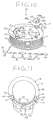
- an electromagnetic coil assembly comprises a bobbin 41 molded from plastic.
- Bobbin 41 includes a central tubular spool 41a and a pair of annular flanges 41b, 41c which project radially from the ends of spool 41a.
- a coil 44 is supported by bobbin 41 and is formed by multiple turns of electric wire 43 wound on spool 41a between flanges 41b, 41c.
- Thermal protection device 47 which has a pair of leads 45, 46 extending from both ends, is disposed on the outer surface of flange 41b.
- One end of lead 45 of thermal protection device 47 is secured to lead 50, which is connected to the power source (not shown), through caulking terminal 48.
- the other end of lead 46 of thermal protection device 47 is connected to electric wire 43 through caulking terminal 49.
- bobbin 41 is inserted into the inner portion of the housing, which has a U-shaped cross section, so that the outer end of flange 41b faces towards the opening in the housing. Thereafter, the cavity defined by bobbin 41, the housing and outer surface 41b are filled with a heated epoxy resin. As the resin hardens, coil 44 is fixed within the cavity.
- Thermal protection device 47 is disposed adjacent to the open end of the cavity so that it is responsive to any increase in operating temperature. However, at the same time, thermal protection device 47 must be securely positioned against movement into the clutch rotor, since the clutch rotor is located adjacent the end surface 41b of bobbin 41. Thermal protection device 47 is secured to end surface 41b of bobbin 41 with electrical insulating tape 51, which is generally made of a resin, such a polyester resin or polyethylene terephthalate. Leads 45, 46 of thermal protection device 47 are made of electrically conductive material. Tape 51 insulates leads 45, 46 from clutch rotor.
- Electrical insulating tape 51 generally has a smaller thermal conductivity than electrical epoxy resin. Consequently, when thermal protection device 47 is covered with electrical insulating tape 51 in addition to epoxy resin, the responsiveness of device 47 is reduced proportionately by the thermal conductivity of tape 51. In other words, excessive heat indicative of clutch failure will not reach thermal protection device 47 as quickly due to the presence of electrical insulating tape 51. Furthermore, in the assembly process, it is necessary to fixedly secure thermal protection device 47 on the end surface 41b of bobbin 41 with electrical insulating tape 51. The additional time needed to manipulate bobbin 41 and electrical insulating tape 51 so that thermal protection device 47 is properly positioned and secured is time consuming and reduces the efficiency of the assembly line.
- an electromagnetic coil assembly for an electromagnetic device comprises a bobbin including a cylindrical tubular spool and a pair of annular flanges radially projecting from the spool.
- a multiple turn winding of electrical wire is supported on the spool.
- a thermal protection device includes a pair of lead wires extending from both ends thereof. The first lead wire is connected to one end of the multiple turn winding by a first joining member. The second lead wire is connected to an electric circuit by a second joining member.
- a connecting device is disposed on an outboard surface of the flange of the bobbin. The connecting device, the thermal protection device, the first joining member and the second joining member are on the outboard surface of the flange of the bobbin.
- FIG. 1 is a perspective view of an electromagnetic coil assembly in accordance with the prior art.
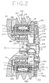
- FIG. 2 is a cross sectional view of an electromagnetic clutch in accordance with a first preferred embodiment.
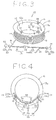
- FIG. 3 is a perspective view of an electromagnetic coil assembly in accordance with the first preferred embodiment.
- FIG. 4 is a plane view of an electromagnetic coil assembly in accordance with the first preferred embodiment.
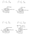
- FIGS. 5a-5d are enlarged cross sectional views of several variations of projection portions in accordance with the first preferred embodiment.
- FIG. 6 is a perspective view of an electromagnetic coil assembly in accordance with a second preferred embodiment.
- FIG. 7 is a plane view of an electromagnetic coil assembly in accordance with the second preferred embodiment.
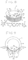
- FIG. 8 is a perspective view of an electromagnetic coil assembly in accordance with a third preferred embodiment.
- FIG. 9 is a plane view of an electromagnetic coil assembly in accordance with the third preferred embodiment.
- FIG. 10 is a perspective view of an electromagnetic coil assembly in accordance with a fourth preferred embodiment.
- FIG. 11 is a plane view of an electromagnetic coil assembly in accordance with the fourth preferred embodiment.
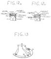
- FIGS. 12a-12b are enlarged cross sectional views of connecting devices in accordance with the fourth preferred embodiment of the present invention.
- FIG. 13 is a perspective view of the connecting means of an electromagnetic coil assembly in accordance with a fifth preferred embodiment.
- Clutch assembly 200 may be coupled to a refrigerant compressor in an automobile air conditioning system (not shown).
- the right side of FIG. 2 will be referred to as the forward or front end, while the left side of FIG. 2 will be referred to as the rearward or rear end.
- a clutch rotor 215, an electromagnetic coil assembly 10, a housing 221 and a bearing 216 generally constitute a driving mechanism of the electromagnetic assembly.
- Hub 224, leaf spring 227, stopper plate 228 and annular armature plate 226 generally constitute the driven mechanism of electromagnetic clutch assembly 200.
- Clutch assembly 200 is coupled with a tubular extension 212 surrounding a compressor drive shaft 213.
- Drive shaft 213 is rotatably supported within housing 211 along horizontal axis X-X by bearings (not shown).
- Hub 224, armature plate 226, and clutch rotor rotate about axis X-X.
- Clutch rotor 215 is made of a magnetic material, such as steel, and comprises an outer annular cylindrical portion 251, an inner annular cylindrical portion 252, and an axial end plate portion 253 which connects the outer and inner portions 251 and 252 at their forward ends.
- an annular U-shaped cavity 255 is defined by portion 251, 252 and 253.
- a plurality of generally V-shaped grooves 218 are provided on the outer peripheral surface of outer annular cylindrical portion 251 for receiving belts (not shown) which couple rotor 215 to the automobile engine (not shown).
- Rotor 215 is rotatably supported on tubular extension 212 of compressor housing 211 by bearing 216, which surrounds the outer surface of tubular extension 212.
- Axial end plate 253 includes one or more concentric slits 219, which are disposed on one or more concentric circles. Slits 219 define a plurality of annular or arcuate magnetic pieces with the surface of the poles on axial end plate 253.
- Electromagnetic coil assembly 10 is disposed in annular cavity 255 of clutch rotor 215 to supply a magnetic flux for attracting armature plate 226 to axial end plate 253. Electromagnetic coil assembly 10 is contained within an annular electromagnetic housing 221. Housing 221 has a generally U-shaped cross section and is affixed, e.g., by welding, to a supporting plate 222, which is secured to the axial end surface of housing 211 by a plurality of rivets 223. A relativity small air gap is maintained between housing 221 and rotor 215.
- Hub 224 comprises a tubular member 241, which is secured tightly on the terminal end portion of drive shaft 213, e.g., by forcible insertion.
- Flange portion 242 extends radially from the front end of tubular member 241 and may be integrally formed with tubular member 241, or formed separately and affixed by a known securing method, such as welding. Relative rotation between hub 224 and drive shaft 213 is prevented by a key-keyhole mechanism 231 provided at the terminal end portion of drive shaft 213.
- Hub 224 is further secured to drive shaft 213 by a nut 225 which is threaded on the terminal end portion of drive shaft 213.
- Annular shim 232 is disposed between the rearward end of tubular member 241 of hub 224 and an annular ridge 232a. Ridge 232a is formed on the outer peripheral surface of the terminal end portion of drive shaft 213. The shim and ridge arrangement allow for the adjustment of the gap between annular armature plate 226 and axial end plate 253.
- Armature plate 226 is made of a magnetic material, is concentric with hub 224, and has a frictional surface 226a which faces frictional surface 253a of axial end plate 253. Armature plate 226 has a plurality of elongated apertures 261 disposed on a concentric circle and is coupled to flange portion 242 of hub 224 through a plurality of leaf springs 227. Each leaf spring 227 is fixed at one end to armature plate 226 by a rivet 231 and at a second end to stopper plate 228. The second ends of leaf springs 227 are secured to spacing member 230 which are in turn secured to flange portion 242 by rivets 229. Accordingly, armature plate 226 may move relative to hub 224 along axis X-X upon the deflection of leaf springs 227.
- electromagnetic coil assembly 10 includes coil bobbin 15 and a multiple turn winding 17 therein.
- Coil bobbin 15 includes a cylindrical tubular spool 12 and a pair of annular flanges 13 and 14 molded integrally with and projecting radially outwardly from tubular spool 12.
- Coil bobbin 15 is preferably made of a polymer, such as nylon, polyester, polyethylene and polyacetal, or may be made of a polymer composite of inorganic or organic materials.
- Multiple turn winding 17 includes electric wire 16, which is repeatedly wound on tubular spool 12.
- Thermal protection device 19 comprises thermal protector 20 and a pair of lead wires 21 and 22 which extend from both sides of thermal protector 20.
- Lead wire 21 of thermal protection device 19 is caulked with first end 18 of electric wire 16 by first fitting member 23.
- Lead wire 22 of thermal protection device 19 is caulked with lead wire 25, which is joined to an external electrical circuit (not shown), by second fitting member 24.
- lead wires 21 and 22 may be brazed to first end 18 of electric wire 16 and lead wire 25.
- the second end (not shown) of electric wire 16 is connected with an external electrical circuit (not shown).
- First and second fitting members 23, 24 include connecting portions 23a, 24a, and preferably include longitudinal tube portions 23b, 24b extending from connecting portions 23a, 24a.
- Outboard surface 13a of flange 13 includes connecting mechanism 26 and guiding mechanism 32 for connecting and guiding thermal protection device 19.
- Connecting mechanism 26 comprises a pair of first projections 27, a pair of second projections 28 and a pair of third projections 29, which are integrally molded as rectangular parallel guides perpendicularly extending from outboard surface 13a.
- One of each of the pair of first projection 27, second projection 28 and third projection 29 axially extend along inner circumferential surface 12a of spool 12.
- Thermal protector 20 and fitting members 23, 24 are respectively inserted between pairs of projections 27, 28, 29.
- Guiding mechanism 32 includes first and second guiding portions 30, 31, which are integrally formed on and perpendicularly extending from outboard surface 13a of flange 13. First and second guiding portions 30, 31 prevent leads 21, 22 from protruding inside of spool 12.
- coil assembly 10 is inserted into the inner hollow portion of housing 221, which is U-shaped in cross section, so that surface 13a of flange 13 faces toward the opening of housing 221. Thereafter, the gaps between coil assembly 10 and housing 221 are filled with heated epoxy resin 11, which hardens as it cools.
- Thermal protection device 19 is responsive to abnormal temperature increases and turns off a circuit controlling the power source to prevent compressor failure.
- thermal protection device 19 is inserted into fitting members 23, 24.
- the effort and precision of assembling thermal protection device 19 is improved over the prior art, without affecting its responsiveness.
- guiding portions 30, 31 prevent leads 21, 22 from snapping, bending, loosening or otherwise interfering with spool 12.
- FIG. 5a shows the basic embodiment in which a pair of projections 29 (27, 28) extend from surface 13a to securely hold thermal protector 20 or fitting members 23, 24.
- FIG. 5b shows a pair of projections 29 (27, 28) may include a pair of small projection portions 52 extending from the extreme end of projections 29 (27, 28).
- FIG. 5c shows a pair of projections 290 (270, 280), which have a gap therebetween, formed so that the width of the gap gradually decreases with distance from surface 13a.
- FIG. 5d shows projection 291 (271, 281), which is hook-shaped to hold thermal protection device 19 with arm portion 291a (271a, 281a). In each of the foregoing embodiments, thermal protection device 19 is securely held by connecting mechanism 26.
- FIGS. 6 and 7 illustrate a second preferred embodiment. Elements in FIGS. 6-7 similar to those in FIGS. 3-4 are designated with the same reference numerals.
- Outboard surface 13a of flange 13 includes connecting mechanism 26 and guiding mechanism 320 for connecting and guiding thermal protection device 19.
- Guiding mechanism 320 includes first and second guiding portions 300, 310, which are integrally formed on and perpendicularly extend from outboard surface 13a of flange 13. Third projection 29 is positioned between first and second guiding portions 300, 310. Guiding portions 300, 310 are hook-shaped and prevent leads 21, 22 from protruding into the inner hollow portion of spool 12.
- FIGS. 8 and 9 illustrate a third preferred embodiment. Elements in FIG. 8 similar to those in FIG. 4 are designated with the same reference numerals.
- Outboard surface 13a of flange 13 includes connecting mechanism 260 and guiding mechanism 32 for connecting and guiding thermal protection device 19 thereon.
- Connecting mechanism 260 comprises a pair of first projections 27, a pair of second projections 28, a third projection 290 and a fourth projection 291, all of which are integrally molded thereon.
- Third projection 290 is rectangularly shaped and axially extends from outboard surface 13a of flange 13.
- Fourth projection 291 is substantially parallel to third projection 290, and includes first portion 291a and a pair of second portions 291b extending from both ends of first portion 291a A pair of second portions 291b prevent leads 21, 22 from protruding into the inner hollow portion of spool 12.
- FIGS. 10, 11 and 12a illustrate a third preferred embodiment. Elements in FIG. 10 similar to those in FIG. 4 are designated with the same reference numerals.
- Outboard surface 13a of flange 13 includes connecting mechanism 261 and guiding mechanism 32 for connecting and guiding thermal protection device 19.
- Connecting mechanism 261 comprises a pair of first projections 105, a pair of second projections 106 and a pair of third projections 29, which are rectangularly shaped and perpendicularly extend from outboard surface 13a of flange 13 so as to be parallel.
- connecting mechanism 261 includes first and second supporting projections 113, 114 formed adjacent to first and second projections 105, 106, and perpendicularly extending from outboard surface 13a of flange 13.
- Connecting mechanism 261 further includes first and second cap members 107, 108 for covering and securing first and second fitting members 23, 24 to outboard surface 13a of flange 13.
- Cap members 107, 108 include first plate portions 107a, 108a, second plate portions 107b, 108b perpendicularly extending from one end of first plate portions 107a, 108a, and third plate portions 107c, 108c perpendicularly extending from the other end of first plate portions 107a, 108a.
- cap members 107, 108 respectively include openings 111, 112 formed on the center of first plate portions 107a, 108a.
- First and second supporting projections 113, 114 are inserted into openings 111, 112. In this arrangement, first and second fitting members 23, 24 are secured to outboard surface 13a of flange 13 between first and second projections 105, 106 and covered by cap members 107, 108.
- a connecting mechanism 261 includes first and second flexible cap members 117, 118 for covering first and second fittings 23, 24.
- Flexible cap members 117, 118 include first plate portions 117a, 118a, second plate portions 117b, 118b perpendicularly extending from one end of first plate portions 117a and 118a, and third plate portions 117c, 118c perpendicularly extending from spool 12 to the other end of first plate portions 117a, 118a.
- flexible cap members 117, 118 respectively include hook portions 117d, 118d formed on the extreme end thereof. Hook portions 117d, 118d hold flexible cap members 117, 118 to flange 14 or bobbin 15.
- FIG. 13 depicts connecting mechanism 26 formed on an arc-shaped plate 34.
- the arc of plate 34 is shaped similar to outboard surface 13a of flange 13.
- Plate 34 may be secured to outboard surface 13a of flange 13 by adhesive materials.
- the embodiment of FIG. 13 has substantially the same advantages as those of the preceding embodiments.
Landscapes
- Engineering & Computer Science (AREA)
- General Engineering & Computer Science (AREA)
- Physics & Mathematics (AREA)
- Mechanical Engineering (AREA)
- Electromagnetism (AREA)
- Fluid Mechanics (AREA)
- Electromagnets (AREA)
- Hydraulic Clutches, Magnetic Clutches, Fluid Clutches, And Fluid Joints (AREA)
- Insulation, Fastening Of Motor, Generator Windings (AREA)
- Coils Of Transformers For General Uses (AREA)
Applications Claiming Priority (3)
| Application Number | Priority Date | Filing Date | Title |
|---|---|---|---|
| JP78279/95 | 1995-03-08 | ||
| JP7827995 | 1995-03-08 | ||
| JP7078279A JP2770938B2 (ja) | 1995-03-08 | 1995-03-08 | 電磁装置 |
Publications (3)
| Publication Number | Publication Date |
|---|---|
| EP0741254A2 true EP0741254A2 (de) | 1996-11-06 |
| EP0741254A3 EP0741254A3 (de) | 1998-04-08 |
| EP0741254B1 EP0741254B1 (de) | 2002-07-31 |
Family
ID=13657534
Family Applications (1)
| Application Number | Title | Priority Date | Filing Date |
|---|---|---|---|
| EP96103384A Expired - Lifetime EP0741254B1 (de) | 1995-03-08 | 1996-03-05 | Spulenanordnung für elektromagnetische Vorrichtung |
Country Status (4)
| Country | Link |
|---|---|
| US (1) | US6091590A (de) |
| EP (1) | EP0741254B1 (de) |
| JP (1) | JP2770938B2 (de) |
| DE (1) | DE69622629T2 (de) |
Cited By (8)
| Publication number | Priority date | Publication date | Assignee | Title |
|---|---|---|---|---|
| EP0848180A1 (de) * | 1996-12-16 | 1998-06-17 | Ogura Clutch Co., Ltd. | Elektromagnetische Kupplungsvorrichtung |
| US5984069A (en) * | 1998-01-19 | 1999-11-16 | Ogura Clutch Co., Ltd. | Electromagnetic clutch |
| EP0903512A3 (de) * | 1997-09-17 | 2000-03-01 | Denso Corporation | Elektromagnetische Kupplung |
| FR2805580A1 (fr) * | 2000-02-29 | 2001-08-31 | Sanden Corp | Assemblage d'enroulement electromagnetique pour appareil electromagnetique |
| US6707365B2 (en) | 2001-10-30 | 2004-03-16 | Sanden Corporation | Electromagnetic coupling apparatus |
| DE19740236B4 (de) * | 1996-09-12 | 2008-06-05 | Denso Corp., Kariya | Elektromagnetische Kupplung |
| WO2014146969A3 (de) * | 2013-03-18 | 2014-12-04 | Erwin A. Lang Gmbh & Co. Kg | Elektromagnetische kupplungsvorrichtung |
| CN104315032A (zh) * | 2014-08-19 | 2015-01-28 | 上海金山易通汽车离合器有限公司 | 一种新型汽车空调离合器线圈环部件及制作方法 |
Families Citing this family (19)
| Publication number | Priority date | Publication date | Assignee | Title |
|---|---|---|---|---|
| JP2770938B2 (ja) * | 1995-03-08 | 1998-07-02 | サンデン株式会社 | 電磁装置 |
| JP3627313B2 (ja) * | 1995-03-29 | 2005-03-09 | 株式会社デンソー | 電磁クラッチ |
| JP3069044B2 (ja) * | 1996-05-07 | 2000-07-24 | サンデン株式会社 | 電磁連結装置 |
| JPH10110744A (ja) * | 1996-10-07 | 1998-04-28 | Sanden Corp | 電磁クラッチ用電磁石 |
| KR19990057639A (ko) * | 1997-12-30 | 1999-07-15 | 신영주 | 전자클러치의 필드코어 |
| KR100531658B1 (ko) * | 1998-12-31 | 2006-01-27 | 한라공조주식회사 | 전자클러치의 필드 코일 조립체_ |
| JP2001317564A (ja) | 2000-02-29 | 2001-11-16 | Sanden Corp | 電磁クラッチ用ヨーク |
| JP2001241468A (ja) | 2000-02-29 | 2001-09-07 | Sanden Corp | 電磁クラッチ用ヨーク |
| JP2001332418A (ja) | 2000-05-23 | 2001-11-30 | Sanden Corp | コイルボビン |
| JP2003074596A (ja) | 2001-09-03 | 2003-03-12 | Sanden Corp | 電磁クラッチ用ヨーク |
| CN100398728C (zh) * | 2002-06-11 | 2008-07-02 | 乐金电子(天津)电器有限公司 | 洗衣机的动力传递用螺线管的构造 |
| FR2882411A1 (fr) * | 2005-02-24 | 2006-08-25 | Sanden Corp | Embrayage electromagnetique pour compresseur. |
| KR100784220B1 (ko) * | 2007-05-08 | 2007-12-10 | 김영국 | 전자석 코일 |
| US20090251257A1 (en) * | 2008-04-03 | 2009-10-08 | Gerald Stelzer | Wiring Assembly And Method of Forming A Channel In A Wiring Assembly For Receiving Conductor and Providing Separate Regions of Conductor Contact With The Channel |
| PL2465120T3 (pl) | 2009-08-11 | 2014-06-30 | Litens Automotive Inc | Elektromagnes i zespół cewki elektromagnetycznej |
| WO2011057168A2 (en) | 2009-11-06 | 2011-05-12 | Electric Gorilla Llc | Dynamoelectric devices |
| JP5927924B2 (ja) * | 2012-01-17 | 2016-06-01 | 株式会社デンソー | 電磁クラッチ |
| JP2018076955A (ja) | 2016-11-11 | 2018-05-17 | サンデン・オートモーティブコンポーネント株式会社 | 電磁クラッチ及びこれを備えた圧縮機 |
| JP6647723B1 (ja) * | 2019-07-31 | 2020-02-14 | 株式会社エス・エッチ・ティ | カレントトランスモジュール |
Family Cites Families (29)
| Publication number | Priority date | Publication date | Assignee | Title |
|---|---|---|---|---|
| GB917200A (en) * | 1960-05-17 | 1963-01-30 | Cav Ltd | Improved bobbin for a solenoid |
| US3130355A (en) * | 1961-05-03 | 1964-04-21 | Warner Electric Brake & Clkutc | Electromagnet |
| GB1278257A (en) * | 1968-08-16 | 1972-06-21 | Bsr Ltd | Improvements relating to bobbin assemblies |
| US4181393A (en) * | 1978-03-17 | 1980-01-01 | Amp Incorporated | Interconnecting means for coil windings and overload protector |
| US4419536A (en) * | 1979-10-23 | 1983-12-06 | North American Philips Consumer Electronics Corp. | Means for affixing an electronic component on a supporting medium |
| JPS56138529A (en) * | 1980-03-31 | 1981-10-29 | Hitachi Ltd | Electromagnetic clutch |
| US4432446A (en) * | 1980-06-28 | 1984-02-21 | Nippondenso Co., Ltd. | Electromagnetic coupling apparatus |
| US4404534A (en) * | 1980-10-14 | 1983-09-13 | General Signal Corporation | Electromagnetic assembly |
| JPS57135680A (en) * | 1981-02-12 | 1982-08-21 | Murata Mfg Co Ltd | Flyback transformer |
| US4503413A (en) * | 1982-12-09 | 1985-03-05 | Telefonbau Und Normalzeit Gmbh | Spool for transformer in power supply device |
| JPS60193309A (ja) * | 1984-03-15 | 1985-10-01 | Murata Mfg Co Ltd | フライバツクトランス |
| DE3430927A1 (de) * | 1984-08-22 | 1986-03-06 | Bosch-Siemens Hausgeräte GmbH, 7000 Stuttgart | Elektromagnetanordnung mit ueberhitzungsschutz |
| US4557544A (en) * | 1984-12-17 | 1985-12-10 | Amp Incorporated | Terminal for connecting a lead wire to a coil wire |
| DE3545821A1 (de) * | 1985-12-23 | 1987-07-02 | Wankel Gmbh | Fluessigkeitsgekuehltes gehaeuse einer rotationskolbenbrennkraftmaschine |
| KR940001991B1 (ko) * | 1986-02-03 | 1994-03-12 | 산덴 가부시기가이샤 | 전자기 클러치 |
| DE3816965C2 (de) * | 1988-05-18 | 1993-11-04 | Zinser Textilmaschinen Gmbh | Vorrichtung zur ermittlung von fadenbruch bei einer ringspinn- oder zwirnmaschine |
| JP2744442B2 (ja) * | 1988-10-15 | 1998-04-28 | 松下電器産業株式会社 | トランス |
| JPH02248969A (ja) * | 1989-03-22 | 1990-10-04 | Matsushita Electric Ind Co Ltd | 画像形成装置 |
| US5307038A (en) * | 1989-03-28 | 1994-04-26 | Ogura Clutch Co., Ltd. | Electromagnetic coupling apparatus |
| US4935713A (en) * | 1989-06-12 | 1990-06-19 | Ford Motor Company | Field coil assembly for an electromagnetically actuated clutch |
| US4987986A (en) * | 1989-07-24 | 1991-01-29 | General Motors Corporation | Electromagnetically actuated valve plate for a viscous fluid fan clutch |
| JP2568051Y2 (ja) * | 1989-10-13 | 1998-04-08 | サンデン株式会社 | 電磁クラッチの励磁装置 |
| US5225801A (en) * | 1990-04-28 | 1993-07-06 | Toyo Denso Kabushiki Kaisha | Ignition coil device for engine |
| US5138293A (en) * | 1990-09-17 | 1992-08-11 | Ogura Clutch, Co., Ltd. | Terminal connection structure of electromagnetic coupling device |
| US5320206A (en) * | 1993-05-03 | 1994-06-14 | Ogura Corporation | Coil mounting and terminals for an electromagnetic clutch |
| US5508671A (en) * | 1994-08-09 | 1996-04-16 | Qgura Clutch Co., Ltd. | Electromagnetic coupling device |
| DE9417532U1 (de) * | 1994-11-02 | 1996-03-07 | Robert Bosch Gmbh, 70469 Stuttgart | Verbindungsanordnung im Automobilbau |
| JP2770938B2 (ja) * | 1995-03-08 | 1998-07-02 | サンデン株式会社 | 電磁装置 |
| GB0713497D0 (en) * | 2007-07-11 | 2007-08-22 | Angiomed Ag | Device for catheter sheath retraction |
-
1995
- 1995-03-08 JP JP7078279A patent/JP2770938B2/ja not_active Expired - Lifetime
-
1996
- 1996-03-05 DE DE69622629T patent/DE69622629T2/de not_active Expired - Lifetime
- 1996-03-05 EP EP96103384A patent/EP0741254B1/de not_active Expired - Lifetime
- 1996-03-05 US US08/611,213 patent/US6091590A/en not_active Expired - Lifetime
Cited By (13)
| Publication number | Priority date | Publication date | Assignee | Title |
|---|---|---|---|---|
| DE19740236B4 (de) * | 1996-09-12 | 2008-06-05 | Denso Corp., Kariya | Elektromagnetische Kupplung |
| EP0848180A1 (de) * | 1996-12-16 | 1998-06-17 | Ogura Clutch Co., Ltd. | Elektromagnetische Kupplungsvorrichtung |
| US5967282A (en) * | 1996-12-16 | 1999-10-19 | Ogura Clutch Company, Ltd. | Electromagnetic coupling device |
| EP0903512A3 (de) * | 1997-09-17 | 2000-03-01 | Denso Corporation | Elektromagnetische Kupplung |
| US6138809A (en) * | 1997-09-17 | 2000-10-31 | Denso Corporation | Insulated electromagnetic coil for electromagnetic clutch |
| US5984069A (en) * | 1998-01-19 | 1999-11-16 | Ogura Clutch Co., Ltd. | Electromagnetic clutch |
| FR2805580A1 (fr) * | 2000-02-29 | 2001-08-31 | Sanden Corp | Assemblage d'enroulement electromagnetique pour appareil electromagnetique |
| US6587024B2 (en) | 2000-02-29 | 2003-07-01 | Sanden Corporation | Electromagnetic coil assembly for electromagnetic apparatus |
| US6842102B2 (en) | 2000-02-29 | 2005-01-11 | Sanden Corporation | Electromagnetic coil assembly for electromagnetic apparatus |
| US6707365B2 (en) | 2001-10-30 | 2004-03-16 | Sanden Corporation | Electromagnetic coupling apparatus |
| WO2014146969A3 (de) * | 2013-03-18 | 2014-12-04 | Erwin A. Lang Gmbh & Co. Kg | Elektromagnetische kupplungsvorrichtung |
| US9906115B2 (en) | 2013-03-18 | 2018-02-27 | Erwin A. Lang Gmbh & Co. Kg | Electromagnetic coupling apparatus |
| CN104315032A (zh) * | 2014-08-19 | 2015-01-28 | 上海金山易通汽车离合器有限公司 | 一种新型汽车空调离合器线圈环部件及制作方法 |
Also Published As
| Publication number | Publication date |
|---|---|
| JP2770938B2 (ja) | 1998-07-02 |
| DE69622629T2 (de) | 2003-02-13 |
| EP0741254A3 (de) | 1998-04-08 |
| EP0741254B1 (de) | 2002-07-31 |
| DE69622629D1 (de) | 2002-09-05 |
| US6091590A (en) | 2000-07-18 |
| JPH08247171A (ja) | 1996-09-24 |
Similar Documents
| Publication | Publication Date | Title |
|---|---|---|
| EP0741254B1 (de) | Spulenanordnung für elektromagnetische Vorrichtung | |
| US4432446A (en) | Electromagnetic coupling apparatus | |
| US5967282A (en) | Electromagnetic coupling device | |
| US5508671A (en) | Electromagnetic coupling device | |
| JP3837786B2 (ja) | 電磁クラッチ | |
| US8264313B2 (en) | Linear solenoid for vehicle | |
| JPH08326782A (ja) | 電磁クラッチ | |
| US20150014117A1 (en) | Electromagnetic Clutch | |
| US6169347B1 (en) | Rotating coil electromagnetic clutch | |
| US20160053829A1 (en) | Electromagnetic Clutch | |
| US5996759A (en) | Coil-rotation type electromagnetic clutch | |
| JPH07127662A (ja) | 電磁クラッチ | |
| US6138809A (en) | Insulated electromagnetic coil for electromagnetic clutch | |
| KR200353562Y1 (ko) | 전자석 클러치의 필드코어 어셈블리 | |
| JP2002039214A (ja) | 電磁クラッチ | |
| US6504465B2 (en) | Electromagnetic coil assembly for electromagnetic apparatus | |
| JP2663364B2 (ja) | 電磁連結装置 | |
| JP3254852B2 (ja) | 電磁クラッチのコネクタ一体ステータにおけるスプールと端子との結合方法 | |
| KR200382537Y1 (ko) | 보빈어셈블리및이것을이용한전자석클러치 | |
| JP3498355B2 (ja) | 電磁クラッチ | |
| JP3130230B2 (ja) | 電磁連結装置の励磁装置 | |
| JP2000230579A (ja) | 電磁クラッチ | |
| JP2006292010A (ja) | 温度ヒューズ固定用ホルダー、コイルボビン及び電磁クラッチ | |
| JPS6039540Y2 (ja) | 電磁クラツチの励磁装置 | |
| JPH1137179A (ja) | 電磁連結装置 |
Legal Events
| Date | Code | Title | Description |
|---|---|---|---|
| PUAI | Public reference made under article 153(3) epc to a published international application that has entered the european phase |
Free format text: ORIGINAL CODE: 0009012 |
|
| AK | Designated contracting states |
Kind code of ref document: A2 Designated state(s): DE FR GB IT SE |
|
| PUAL | Search report despatched |
Free format text: ORIGINAL CODE: 0009013 |
|
| RHK1 | Main classification (correction) |
Ipc: F16D 9/02 |
|
| AK | Designated contracting states |
Kind code of ref document: A3 Designated state(s): DE FR GB IT SE |
|
| 17P | Request for examination filed |
Effective date: 19980623 |
|
| 17Q | First examination report despatched |
Effective date: 20000911 |
|
| GRAG | Despatch of communication of intention to grant |
Free format text: ORIGINAL CODE: EPIDOS AGRA |
|
| GRAG | Despatch of communication of intention to grant |
Free format text: ORIGINAL CODE: EPIDOS AGRA |
|
| GRAH | Despatch of communication of intention to grant a patent |
Free format text: ORIGINAL CODE: EPIDOS IGRA |
|
| GRAH | Despatch of communication of intention to grant a patent |
Free format text: ORIGINAL CODE: EPIDOS IGRA |
|
| GRAA | (expected) grant |
Free format text: ORIGINAL CODE: 0009210 |
|
| AK | Designated contracting states |
Kind code of ref document: B1 Designated state(s): DE FR GB IT SE |
|
| PG25 | Lapsed in a contracting state [announced via postgrant information from national office to epo] |
Ref country code: IT Free format text: LAPSE BECAUSE OF FAILURE TO SUBMIT A TRANSLATION OF THE DESCRIPTION OR TO PAY THE FEE WITHIN THE PRESCRIBED TIME-LIMIT;WARNING: LAPSES OF ITALIAN PATENTS WITH EFFECTIVE DATE BEFORE 2007 MAY HAVE OCCURRED AT ANY TIME BEFORE 2007. THE CORRECT EFFECTIVE DATE MAY BE DIFFERENT FROM THE ONE RECORDED. Effective date: 20020731 |
|
| REG | Reference to a national code |
Ref country code: GB Ref legal event code: FG4D |
|
| REF | Corresponds to: |
Ref document number: 69622629 Country of ref document: DE Date of ref document: 20020905 |
|
| PG25 | Lapsed in a contracting state [announced via postgrant information from national office to epo] |
Ref country code: SE Free format text: LAPSE BECAUSE OF FAILURE TO SUBMIT A TRANSLATION OF THE DESCRIPTION OR TO PAY THE FEE WITHIN THE PRESCRIBED TIME-LIMIT Effective date: 20021031 |
|
| ET | Fr: translation filed | ||
| PG25 | Lapsed in a contracting state [announced via postgrant information from national office to epo] |
Ref country code: GB Free format text: LAPSE BECAUSE OF NON-PAYMENT OF DUE FEES Effective date: 20030305 |
|
| PLBE | No opposition filed within time limit |
Free format text: ORIGINAL CODE: 0009261 |
|
| STAA | Information on the status of an ep patent application or granted ep patent |
Free format text: STATUS: NO OPPOSITION FILED WITHIN TIME LIMIT |
|
| 26N | No opposition filed |
Effective date: 20030506 |
|
| GBPC | Gb: european patent ceased through non-payment of renewal fee |
Effective date: 20030305 |
|
| PGFP | Annual fee paid to national office [announced via postgrant information from national office to epo] |
Ref country code: FR Payment date: 20130315 Year of fee payment: 18 |
|
| PGFP | Annual fee paid to national office [announced via postgrant information from national office to epo] |
Ref country code: DE Payment date: 20130328 Year of fee payment: 18 |
|
| REG | Reference to a national code |
Ref country code: DE Ref legal event code: R119 Ref document number: 69622629 Country of ref document: DE |
|
| REG | Reference to a national code |
Ref country code: FR Ref legal event code: ST Effective date: 20141128 |
|
| REG | Reference to a national code |
Ref country code: DE Ref legal event code: R119 Ref document number: 69622629 Country of ref document: DE Effective date: 20141001 |
|
| PG25 | Lapsed in a contracting state [announced via postgrant information from national office to epo] |
Ref country code: DE Free format text: LAPSE BECAUSE OF NON-PAYMENT OF DUE FEES Effective date: 20141001 Ref country code: FR Free format text: LAPSE BECAUSE OF NON-PAYMENT OF DUE FEES Effective date: 20140331 |