EP0741262A2 - Kraftfahrzeugscheinwerfer mit einer zum Erzeugen des Lichtbündels durch Reflektion bearbeiteten reflektierenden Fläche - Google Patents
Kraftfahrzeugscheinwerfer mit einer zum Erzeugen des Lichtbündels durch Reflektion bearbeiteten reflektierenden Fläche Download PDFInfo
- Publication number
- EP0741262A2 EP0741262A2 EP96104681A EP96104681A EP0741262A2 EP 0741262 A2 EP0741262 A2 EP 0741262A2 EP 96104681 A EP96104681 A EP 96104681A EP 96104681 A EP96104681 A EP 96104681A EP 0741262 A2 EP0741262 A2 EP 0741262A2
- Authority
- EP
- European Patent Office
- Prior art keywords
- vehicle headlight
- circle
- arcs
- headlight
- parabola
- Prior art date
- Legal status (The legal status is an assumption and is not a legal conclusion. Google has not performed a legal analysis and makes no representation as to the accuracy of the status listed.)
- Withdrawn
Links
Images


Classifications
-
- F—MECHANICAL ENGINEERING; LIGHTING; HEATING; WEAPONS; BLASTING
- F21—LIGHTING
- F21V—FUNCTIONAL FEATURES OR DETAILS OF LIGHTING DEVICES OR SYSTEMS THEREOF; STRUCTURAL COMBINATIONS OF LIGHTING DEVICES WITH OTHER ARTICLES, NOT OTHERWISE PROVIDED FOR
- F21V7/00—Reflectors for light sources
- F21V7/04—Optical design
-
- F—MECHANICAL ENGINEERING; LIGHTING; HEATING; WEAPONS; BLASTING
- F21—LIGHTING
- F21S—NON-PORTABLE LIGHTING DEVICES; SYSTEMS THEREOF; VEHICLE LIGHTING DEVICES SPECIALLY ADAPTED FOR VEHICLE EXTERIORS
- F21S41/00—Illuminating devices specially adapted for vehicle exteriors, e.g. headlamps
- F21S41/30—Illuminating devices specially adapted for vehicle exteriors, e.g. headlamps characterised by reflectors
- F21S41/32—Optical layout thereof
- F21S41/33—Multi-surface reflectors, e.g. reflectors with facets or reflectors with portions of different curvature
- F21S41/337—Multi-surface reflectors, e.g. reflectors with facets or reflectors with portions of different curvature the reflector having a structured surface, e.g. with facets or corrugations
Definitions
- the present invention refers to headlights for motor vehicles comprising a reflector equipped with a worked or "carved” reflecting surface for shaping the light beam through reflection only.
- headlights for vehicles designed for generating light beams for lower (traffic) beams and/or upper (driving) beams or to be mounted in fog lights, rear fog lights, backing lamps and the like are generally provided with a paraboidal or ellipsoidal reflector member with the filament of a lamp located near the focus thereof in a relationship depending on the function to be accomplished by the headlight.
- the light which has been reflected by the reflector is then "shaped" by refraction through either a lens (for ellipsoidal reflectors) or one or more systems comprising lenses and prisms (for parabolic reflectors) in order to obtain the desired light distribution.
- a lens for ellipsoidal reflectors
- prisms for parabolic reflectors
- the transparent refractor needs to be located very precisely in respect of the reflector and its angle of inclination is limited to a maximum value of 30° (with respect to the horizontal plane) because of light penetration and dispersion phoenomena, and because of the manufacturing technique. Additionally, an uneven thickness of such transparent means causes an absorption of the light beam that can be between 25% and 30% of the overall light intensity.
- the object of the present invention is to overcome the above mentioned drawbacks, particularly the absorption inconvenience, by shaping the light beam distribution directly through the reflector, thus eliminating the need of a refracting device which is replaced by a simple clear transparent glass with the only function of protecting the reflector.
- An essential feature of the headlight according to the present invention consists in that the reflector "shapes", i.e. modifies the light beam thanks to a composite reflecting surface formed by a plurality of adjacent columnar reflecting portions profiled - in a transverse cross section - as arcs of circles with the ends of such arcs located on a reference curve formed by one or more segments of conics.
- the reflector according to the invention allows for a quick design and check, and the resulting surface is uniform and aesthetically pleasant.
- the beam shaping is accomplished through a modification of the surface of the reflector by replacing the profile of a "reference" paraboloid (or other surface of revolution) with a plurality of adjacent columnar reflecting surfaces (also called lenses) the cross sections of which are arcs of circles with both ends lying on two predetermined points of the reference parabola (or other conic curve) in the plane of the cross-section.
- the parameters of said arcs of circles such as radius and length, are selected so that the reflection of a filament light in the intersection point reaches a plane (perpendicular to the optical axis) at an assigned distance from the center of such plane.
- the cross-section curve formed by the plurality of adjacent arcs of circles is then vertically shifted along a conic directrix that can be an arm of a parabola, of an ellipse, of a circle, or a curve made up by a combination of more conics.
- the reference parabola be formed by a segment of a single curve; it can be formed by properly selected segments of parabolas having different focuses or foci. More generally the reflector member can be formed by one or more portion of surfaces of revolution.
- the reflecting lens pitch (length of the sector) can be either constant or variable, in accordance with the design needs.
- the reflector of the invention works with any filament of any lamp that has been approved for motor vehicles (with or without a shielding cup).
- the shape of the headlight when seen frontally, can have any suitable shape e.g. round, squared, rectangular or elliptical.
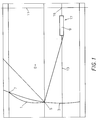
- the cross-section profile of a parabolic reflector is modified by replacing an arc of the reference conic with an arc of circle 1 the ends 5, 7 of which rest on the conic 3, and more precisely are coincident with the ends of the arc to be replaced.
- a light ray from the filament 9 of a lamp 17 located near the focus of the reference parabola 3 is reflected by the curve 1, at point 5 or 7, onto a plane 11 at an assigned distance from the center point 15 defined by the intersection of plane 11 with the optical axis 13.
- the above profile is easily designed and verified, and at the same time leads to a uniform surface that is aesthetically pleasant.
- More particularly such modelling is carried out through arcs of circle 1 that rest (i.e. start and terminate) on the profile of the reference parabola 3, i.e. for the or each arc of circle both ends coincide with the ends of the arc of the reference parabola to be replaced.
- the arcs of circle are selected so that a light ray from the filament 9 is reflected by said intersection points 3 or 5 into a plane 11 (that is orthogonal to the optical axis 13) at an assigned distance from the center point 15 defined by the intersection of plane 11 with the optical axis 13.
- the so obtained curve is then vertically shifted or reproduced along a directrix of the reference conic that can be a parabola, an ellipse, a circle or a combination of more conic sections.
- the curved edges of each of the adjacent columnar reflecting surfaces 1 lie on the surface of the reference paraboloid (or other selected surface of rotation).
- the pitch of the reflecting lens (that is the length of the sector) can be either constant or variable.
- the distance between the end points 5 and 7, as measured perpendicularly to the optical axis 13, is kept constant.
- any filament 9 of any lamp 17 that has been officially approved for motor vehicles can be used in the headlight of the invention (with or without a cup).
- the headlight frontally can have any shape, such as round, squared, rectangular (as shown in Fig. 5) or elliptical.
- FIG. 3 shows a perspective view of a reflector 19 according to the invention and Fig. 4 illustrates a reflector 19' of the prior art.
Landscapes
- Engineering & Computer Science (AREA)
- General Engineering & Computer Science (AREA)
- Non-Portable Lighting Devices Or Systems Thereof (AREA)
Applications Claiming Priority (2)
| Application Number | Priority Date | Filing Date | Title |
|---|---|---|---|
| IT95RM000214A IT1276514B1 (it) | 1995-04-03 | 1995-04-03 | Proiettore per veicoli con riflettore "lentinato" per modellare il flusso luminoso tramite riflessione. |
| ITRM950214 | 1995-04-03 |
Publications (2)
| Publication Number | Publication Date |
|---|---|
| EP0741262A2 true EP0741262A2 (de) | 1996-11-06 |
| EP0741262A3 EP0741262A3 (de) | 1997-01-08 |
Family
ID=11403234
Family Applications (1)
| Application Number | Title | Priority Date | Filing Date |
|---|---|---|---|
| EP96104681A Withdrawn EP0741262A3 (de) | 1995-04-03 | 1996-03-25 | Kraftfahrzeugscheinwerfer mit einer zum Erzeugen des Lichtbündels durch Reflektion bearbeiteten reflektierenden Fläche |
Country Status (2)
| Country | Link |
|---|---|
| EP (1) | EP0741262A3 (de) |
| IT (1) | IT1276514B1 (de) |
Cited By (5)
| Publication number | Priority date | Publication date | Assignee | Title |
|---|---|---|---|---|
| FR2821148A1 (fr) * | 2001-02-20 | 2002-08-23 | Koito Mfg Co Ltd | Procede de determination de la surface reflechissante d'un reflecteur, et lampe de vehicule |
| EP1338468A3 (de) * | 2002-02-26 | 2007-03-07 | Ichikoh Industries, Ltd. | Leuchte für Fahrzeuge |
| ITMI20090363A1 (it) * | 2009-03-11 | 2010-09-12 | Grechi Illuminazione S R L | Sorgente luminosa a led con unità di convogliamento integrata |
| DE19837795B4 (de) * | 1997-09-03 | 2013-10-31 | Valeo Vision | Spiegel für einen Kurvenscheinwerfer eines Kraftfahrzeugs und Scheinwerfer, der ihn enthält |
| AT15697U1 (de) * | 2016-03-29 | 2018-04-15 | Zkw Group Gmbh | Fahrzeugscheinwerfer mit einem Reflektor |
Family Cites Families (5)
| Publication number | Priority date | Publication date | Assignee | Title |
|---|---|---|---|---|
| US1390747A (en) * | 1920-06-15 | 1921-09-13 | Flatlite Ltd | Reflector for use in light-projectors |
| US2565757A (en) * | 1946-06-05 | 1951-08-28 | Electric Auto Lite Co | Multibeam head lamp incorporating gradually fluted reflector and pluraality of filaments |
| FR2460442A1 (fr) * | 1979-06-29 | 1981-01-23 | Cibie Projecteurs | Nouvelle structure de projecteur, notamment de projecteur d'automobile |
| JP2591094B2 (ja) * | 1988-08-23 | 1997-03-19 | 市光工業株式会社 | 自動車用前照灯 |
| JP2610546B2 (ja) * | 1991-01-25 | 1997-05-14 | 株式会社小糸製作所 | 車輌用前照灯の反射鏡 |
-
1995
- 1995-04-03 IT IT95RM000214A patent/IT1276514B1/it active IP Right Grant
-
1996
- 1996-03-25 EP EP96104681A patent/EP0741262A3/de not_active Withdrawn
Cited By (5)
| Publication number | Priority date | Publication date | Assignee | Title |
|---|---|---|---|---|
| DE19837795B4 (de) * | 1997-09-03 | 2013-10-31 | Valeo Vision | Spiegel für einen Kurvenscheinwerfer eines Kraftfahrzeugs und Scheinwerfer, der ihn enthält |
| FR2821148A1 (fr) * | 2001-02-20 | 2002-08-23 | Koito Mfg Co Ltd | Procede de determination de la surface reflechissante d'un reflecteur, et lampe de vehicule |
| EP1338468A3 (de) * | 2002-02-26 | 2007-03-07 | Ichikoh Industries, Ltd. | Leuchte für Fahrzeuge |
| ITMI20090363A1 (it) * | 2009-03-11 | 2010-09-12 | Grechi Illuminazione S R L | Sorgente luminosa a led con unità di convogliamento integrata |
| AT15697U1 (de) * | 2016-03-29 | 2018-04-15 | Zkw Group Gmbh | Fahrzeugscheinwerfer mit einem Reflektor |
Also Published As
| Publication number | Publication date |
|---|---|
| IT1276514B1 (it) | 1997-10-31 |
| ITRM950214A1 (it) | 1996-10-03 |
| EP0741262A3 (de) | 1997-01-08 |
| ITRM950214A0 (it) | 1995-04-03 |
Similar Documents
| Publication | Publication Date | Title |
|---|---|---|
| US4811174A (en) | Vehicle lighting device | |
| US4494176A (en) | Lamps having multiple and aimed parabolic sections for increased useful light output | |
| US6910792B2 (en) | Projection-type vehicular headlamp having improved lateral illumination | |
| US5967647A (en) | Headlight for a vehicle, especially a motor vehicle | |
| US5440456A (en) | Headlight for vehicles | |
| JP2651753B2 (ja) | 光源に改良を加えた自動車用前照灯 | |
| JPH0789447B2 (ja) | 自動車のすれ違いビ−ム又は霧灯用投光器 | |
| JP2003123517A (ja) | 投光ユニットおよび該投光ユニットを具備するled車両用照明灯具 | |
| JP2654116B2 (ja) | 自動車用のすれ違いビームヘッドランプ | |
| JP2003016813A (ja) | プロジェクタ型ランプ | |
| JP3156793B2 (ja) | 自動車用前照灯 | |
| JPH06223601A (ja) | 投光ヘッドランプ装置 | |
| JP2706766B2 (ja) | ヘツドライト系 | |
| EP0355815A3 (de) | Kraftfahrzeugscheinwerfer | |
| US5045982A (en) | Wide angle warning light | |
| EP0432918A2 (de) | Fahrzeugscheinwerfer | |
| US3949214A (en) | Vehicle lamp assembly | |
| JP2591839B2 (ja) | ランプ用反射鏡及びヘッドライトユニット | |
| US1546281A (en) | Reflector | |
| EP0989354B1 (de) | Scheinwerfer für Kraftfahrzeuge | |
| KR0140528B1 (ko) | 자동차용 전조등 | |
| JP3565875B2 (ja) | 自動車に用いられるすれ違いビーム用前照灯 | |
| ITRM950214A1 (it) | Proiettore per veicoli con riflettore "lentinato" per modellare il flusso luminoso tramite riflessione. | |
| RU2009390C1 (ru) | Автомобильная фара ближнего света | |
| JPS6323603B2 (de) |
Legal Events
| Date | Code | Title | Description |
|---|---|---|---|
| PUAI | Public reference made under article 153(3) epc to a published international application that has entered the european phase |
Free format text: ORIGINAL CODE: 0009012 |
|
| AK | Designated contracting states |
Kind code of ref document: A2 Designated state(s): DE ES FR IT |
|
| PUAL | Search report despatched |
Free format text: ORIGINAL CODE: 0009013 |
|
| AK | Designated contracting states |
Kind code of ref document: A3 Designated state(s): DE ES FR IT |
|
| STAA | Information on the status of an ep patent application or granted ep patent |
Free format text: STATUS: THE APPLICATION IS DEEMED TO BE WITHDRAWN |
|
| 18D | Application deemed to be withdrawn |
Effective date: 19970709 |